Premier Mounts Indoor Furnishings PP-FCTA User manual

Category
Projector mounts
Type
User manual

This manual is also suitable for

CEILING MOUNT MODEL
Premier Mounts
3130 E. Miraloma Avenue
Anaheim, CA 92806
Phone: (800) 368-9700 Fax: (800) 832-4888
[email protected] www.mounts.com
9530-302-001-03
INSTALLATION MANUAL
The PP-FCTA is designed
to be installed above the
ceiling tiles.
- 2 -
o Safety & Precaution 2
o Diagrams 3
o Parts list 4
o Plate assembly 4
o Securing the plate 5
o Electrical cut out 6
o Ceiling anchoring 7
The ceiling structure must be capable of supporting at least five (5) times the weight of projector. If not, the ceiling structure
must be reinforced. Proper installation procedure by qualified personnel as outlined in the installations instructions must be
adhered to. Failure to do so could result in serious personal injury.
The entire installation instructions should be fully read and understood, including all of the safety symbols and safety
precautions, before beginning installation. The installation instructions should be read, understood and followed to prevent
personal injury or property damage. Keep these installation instructions in an easily accessible location for future reference.
Indicates that the power plug is to be disconnected
from the power outlet.
Safety precautions must be taken at all times.
Contact Premier Mounts for an
y
q
uestions
Warning and caution in general
Do not install near heater, direct sunlight or air conditioning or any other source of direct heat energy. Failure to do so
may result in damage to the projector.
A qualified person should always perform the installation work.
Safety & Precautions
WARNING: Safety precaution measures must be practiced at all times during the installation of this product. Use proper safety gear and
tools for the installations procedure to prevent personal injury.
- 3 -
SPECS
PART#:
PP-FCTA False ceiling mount
COLOR:
White
A. Ceiling main plate
B. 1½" (NPT) adapter plate
C. Ceiling stud plate
D. (6) Turnbuckle mounting
points
F. (4) Securing points
E. (2) Electrical cut outs
Diagrams
D
A
C
B
E
F
- 4 -
3"
3"
3"
3"
3"
Phillips screwdriver, Pliers, Wire cutters
(Other tools required depending on the installation environment)
Parts List
TOOLS & SUPPLY NEEDED
Plate assembly
Step 1
NOTE: Read all cautions and warnings before
continuing.
Assemble the plate together. Pre-set all the M5 x 16
Phillips screws two (2) on both outer ends of the plate
and one (1)
found on the 1½" (NPT) nipple.
Observe the room and the ceiling; find the proper
location for the projector placement and lightly mark the
bottom of the tile. Remove any of the 24" x 24" or 24" x
48" tiles that are surrounding the marked tile. Measure
3" from the edge of the t-bar to the inside of the tile. The
hole excepting the pipe should be cut anywhere inside
the square. Place the ceiling plate on the t-bar rails. See
figure 1.
HARDWARE
¼-20
Turnbuckles
(Qty 4)
(5) M5 x 16 Phillips
head screws
(Pre-assembled)
¼-20 Wing nuts
(Pre-assembled)
(Qty 4)
14 (GA)
Galvanized steel
wire
¼" x 3"
Lag bolts
(Qty 4)
Escutcheon ring
Loosel
y
install the
p
lates
Ceiling main plate
Slider plate
(4) M5 x 16 Phillips
hex screws
(1) M5 x 16mmPhillip screw
(safety screw)
(4) ¼"-20 wing nuts
1½" (NPT) adapter
p
late
Ceiling stud plate Remove tile
Or any of the
surroundin
g
tiles
T-bar frame rails
Measure and cut
ou
t
Figure 1
- 5 -
Step 2
Cut a hole on the marked tile where the 1½" (NPT) close nipple or
pipe (optional) will be secured to the plate. Position and slide the
stud plate to the hole and secure the ceiling plate to the rails by
tightening the four (4) M5 x 16 Phillips head screws (supplied).
Center the stud plate to the hole and secure the plate by tightening
the four win
g
nuts. See fi
g
ure 2
Securing the plate
Step 3
Secure the 1½" (NPT) nipple to the ceiling plate and secure the nipple
by using one (1) M5 x 16 Phillips head screw (supplied) to the stud
plate.
Tiles
T-bar frame rails
Align with the cut out
and tighten the wing
nuts
Tighten M5 x 16mm Set Screw
to secure the plate to the rail
framing. The M5x16mm screw
may be installed from either the
outside or the inside of the plate.
Ceiling main plate
Ceiling main plate
Tiles
1½" (NPT) nipple
Tighten M5 x
16mm Safety
Screw to secure the
1½" (NPT) nipple
1½" (NPT) nipple
T-bar frame rails
CAUTION: The main ceiling plate has to rest on the t-bar main
frame. Use the four (4) M5 x 16 Phillip head screws to secure the
plate. Failure to do so may result in the instability of the plate.
NOTE: If more ceiling drop is required, use longer pipe call
Premier Mounts Inc For longer pipe size (optional).
CAUTION: The M5 x 16 Phillip head screw must be used to
stabilize the 1½" (NPT) nipple or optional pipe.
Figure 2
Figure 3
- 6 -
CUT
CUT
Electrical cut out
Step 4
NOTE: The electrical installation should be done in accordance
to local codes and regulations.
Cut the tile where the electrical base box is going to be secured.
Using (commercially available) hardware depending on electrical
installation environment, Install the electrical box and secure it to
the plate. Make all electrical connections at this time.
See figure 4 & 5.
Tiles
Ceiling main plate
Electrical box
cut ou
t
Electrical box
(
commerciall
y
available
Tiles
T-bar frame rails
T-bar frame
NOTE: The electrical cut outs allow for a single and square
electrical box installations.
Figure 4
Figure 5
- 7 -
Thank you for choosing PREMIER MOUNTS for your installation needs.
If you have any questions please contact PREMIER MOUNTS
Information is shown on the front of this page.
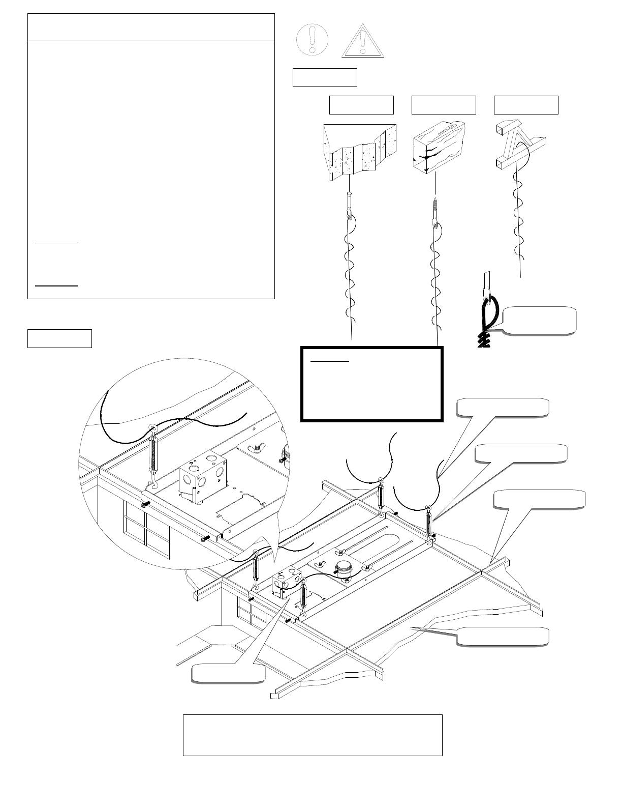
Ceiling anchoring
Step 5
Wood joist: Secure the four (4) ¼" eye lag screws to the wood
joist on the ceiling. Make sure eye lag screws are properly
secured to the joist before securing the wire to the turnbuckles
on the plate.
Concrete: Use (commercially available) suitable hardware
depending on your installation environment. And follow the
instructions below.
Truss ceiling: Use (commercially available) suitable hardware
depending on your installation environment. And follow the
instructions bellow.
Loop the wire through the eye lag screws, anchors, or truss and
twist the wire at least five (5) times itself to secure it. Run the
other end of the wire through the turnbuckle and twist the wire
at least five (5) times around itself to secure it.
See figure 6 & 7.
CAUTION: The final loop on the wire has to tightly bend and
secured to the wire to prevent the wire from untwisting itself.
Twist the turnbuckles to fine tune adjust.
CAUTION: Recheck all hardware and installation for proper
tightness and security and replace the til
e.
Tiles
Ceiling main
Turnbuckles
14 (ga) Wire
14 (ga) Wire
Ti
g
htl
y
secured
Concrete Wood joist Truss
CAUTION: Loop the 14 (ga) wire at
least 5 times around itself. The final
loop has to be secured to prevent the
wire from becoming untied.
Do this for the eye lag screws and
turnbuckles
T-bar frame rails
Figure 6
Figure 7
  • Page 1 1
  • Page 2 2
  • Page 3 3
  • Page 4 4
  • Page 5 5
  • Page 6 6
  • Page 7 7

Premier Mounts Indoor Furnishings PP-FCTA User manual

Category
Projector mounts
Type
User manual
This manual is also suitable for

Ask a question and I''ll find the answer in the document

Finding information in a document is now easier with AI