Page is loading ...

CONTENTS
· Edition 11.23 · 32-00284-02 · EN
EN – www.docuthek.com
V4730C/V8730C/V4734C
1:1 Gas/Air Servo Regulated Valves
1 Safety ................................1
2 Checking the usage .....................2
3 Installation ............................2
4 Wiring................................3
5 Tightness test..........................4
6 Commissioning ........................7
7 Adjust servo regulator.................... 7
8 Maintenance ..........................8
9 Troubleshooting ........................8
10 Accessories ..........................9
11 Technical data .......................10
12 Certification .........................11
13 Logistics ............................11
14 Disposal ............................12
1 SAFETY
1.1 Please read and keep in a safe place
Please read through these instructions
carefully before installing or operating. Following the
installation, pass the instructions on to the operator.
This unit must be installed and commissioned in
accordance with the regulations and standards in
force. These instructions can also be found at www.
docuthek.com.
1.2 Explanation of symbols
1, 2, 3, a, b, c = Action
➔= Instruction
1.3 Liability
We will not be held liable for damage resulting from
non-observance of the instructions and non-com-
pliant use.
1.4 Safety instructions
Information that is relevant for safety is indicated in
the instructions as follows:
DANGER
Indicates potentially fatal situations.
WARNING
Indicates possible danger to life and limb.
CAUTION
Indicates possible material damage.
All interventions may only be carried out by qualified
gas technicians. Electrical interventions may only be
carried out by qualified electricians.
1.5 Conversion, spare parts
All technical changes are prohibited. Only use OEM
spare parts.
OPERATING INSTRUCTIONS
EN

V4730C/V8730C/V4734C · Edition 11.23
EN-2
2 CHECKING THE USAGE
The 1:1 Gas/Air Servo Regulated Valves, with an
additional venturi mixing unit (VMU) and a fan, are
used for modulating premixing units, such as gas
burners, gas boilers, roof units, fresh air units and
process applications.
This function is only guaranteed when used within
the specified limits – see page 10 (11 Technical
data). Any other use is considered as non-compliant.
See instruction sheet VMU "VMU Series Venturi
Mixing Unit for V473xC/V873xC Combination Gas
Controls" www.docuthek.com.
Check the ratings given in the instructions and on
the product to make sure the product is suitable for
your application.
2.1 Type code
V Safety shut-off valve
4 Line voltage
8 Low voltage
73 Combination control
0 Small body size models
4 Large body size models
C Integrated gas/air 1:1
xxxx Specification number
2.2 Part designations
4
6
1
5
2
8
3
7
1 Main body
2 Cover
3 Cap
4 Servo regulator gas/air 1:1
5 Pressure tap points
6 Inlet flange
7 Electrical connection
(connector type: ISO 4400/DIN43650 Form A)
8 Pressure switches (Option)
3 INSTALLATION
CAUTION
Incorrect installation
Please observe the following to ensure that the
unit is not damaged during installation and oper-
ation:
– Sealing material and dirt, e.g. thread cuttings,
must not be allowed to get into the valve
housing.
– Dropping the device can cause permanent
damage. In this event, replace the entire device
and associated modules before use.
– Turn off gas supply before installation.
– Disconnect power supply to the valve actuator
before beginning the installation to prevent
electrical shock and damage to the equipment.
– Do not remove the seal over valve inlet and
outlet, until ready to connect piping.
– The valve must be installed so that the arrow on
the valve points in the direction of the gas flow
(gas pressure helps to close the valve).
– Screws which are protected against unauthor-
ised removal must not be loosened. This will
invalidate the warranty!
3.1 Installation position
Solenoid actuator in the vertical upright position or
tilted up to the horizontal, not upside down.
Gas valves with integrated gas/air 1:1: The factory
settings are made in a horizontal installation position.
A vertical installation may require readjustments.
The distance between the gas valve and the wall/
ground, must be at least 12inch/30 cm.
➔The valve can be mounted up to ±90 degrees
from this position without affecting the fuel/air
metering at medium and high firing rates (3000
to 5000 rpm of the blower), but at lower firing
rates (1000 rpm) the fuel might be reduced up
to 10% when the valve is not mounted horizontal.
To counter this, the low fire gas flow may be
carefully field adjusted for non-horizontal mount-
ing as described below.
3.2 Install valve
1 Take care that dirt does not enter the gas valve
during handling.
2 Remove flanges from the valve (if factory
mounted).

V4730C/V8730C/V4734C · Edition 11.23
EN-3
3 Use new, properly reamed, pipe, free from chips.
4 Apply a moderate amount of good quality pipe
dope, resistant to the action of liquefied
petroleum (LP) gas, only on the pipe threads.
5 Screw the flanges onto the pipes.
6 Ensure that the inlet and outlet flanges are in line
and separate from each other enough to allow
the valve to be mounted between the flanges
without damaging the “O”-ring.
7 Make sure O-ring sealing surfaces are clean.
8 Using general purpose lithium grease, grease the
O-ring.
9 Install the O-ring into the O-ring groove provided
on the valve body (one O-ring per groove).
10 Mount the gas valve between the flanges using
the bolts for each flange.
11 Complete the electrical connections as
instructed in the Electrical Connection section.
12 Complete the electrical connections as
instructed in the wiring section.
3.3 Connections
There are 1/8inch (3mm) NPT pressure taps at the
flanges. At the main body flange connections are
provided to mount either an:
– pressure switches (min. or max.)
– valve proving system (VPS)
3.3.1 Pressure tap points
The following pressures can be measured:
1 Inlet pressure
2 Inlet pressure
3 Interim pressure - unreguleted (pressure between
the two shut-off valves)
4 Outlet pressure - reguleted
P Pilot gas pressure
➔The corresponding numbers can be found on the
sides of the valve. Pressure points 1 and 4 are
located on top of the flanges.
➔A pressure switch can be mounted to 2, P or 3.
(C60VR: Only 2 and 3)
1 4
2 P 3
3P
2
Pressure tap points for small body size models.
4
P 33
P 33
2
1
2
Pressure tap points for large body size model
3.3.2 Legend
Strainer
Pressure
regulator
Pressure
switch
V1
(SSOV)
V2
(SSOV)
Safety
shut-off valve
4 WIRING
WARNING
Risk of injury!
Please observe the following to ensure that no
damage occurs:
– Electric shocks can be fatal! Before working on
possible live components, ensure the unit is
disconnected from the power supply.
– Switch off power supply before making electrical
connections.
– All wiring must comply with local codes,
ordiances and regulations.
– Use lead wire which can withstand 105°C
ambient.
➔Use 14, 16 or 18 AWG copper conductor, 600
volt insulation, moisture-resistant wire for line
voltage connections.
➔Recommended wire types are TTW60C,
THW75C or THHN90C.
– T1 (yellow) will be L2 (120 or 24V AC).
– T2 (black) will be L1 (120 or 24V AC) to Valve 1.
– T3 (blue) will be L1 (120 or 24V AC) to Valve 2.
– Ground (green) will be earth ground.
1 Disconnect the system from the electrical power
supply.
2 Shut off the gas supply.
➔Before wiring, the fitter should ground himself.
3 Wire as shown on the connection diagram.
➔Three pin electrical plug connector according to
ISO 4400/DIN43650 (Form A).
Connector face view
2 = L1V1
1 = N
3 = L1V2
A
2
1
PE
3
4 After successful wiring, continue with page
4 (5 Tightness test) and page 7 (6.1
Adjust valve).

V4730C/V8730C/V4734C · Edition 11.23
EN-4
5 TIGHTNESS TEST
5.1 Checking for tightness
This is a test for checking the closure tightness of
the gas shutoff valve.
It should be performed only by trained, experienced,
flame safeguard technicians during the initial startup
of the burner system or whenever the valve is
replaced.
It is recommended that this test should also be
included in the scheduled inspection and mainte-
nance procedures.
For a periodic inspection test, also follow steps
below.
WARNING
Electrical Shock Hazard. Can cause severe injury
or death.
Please observe the following:
– Remove the power from the system before
beginning the valve leak test to prevent electrical
shock. More than one disconnect may be
involved.
1 De-energize the control system to make sure no
power goes to the valves.
2 Close the upstream manual gas cock A.
SSOV3)
SSOV3)
2)
A B C
D
E
F
4)
upstream
manual
gas cock
gas
supply
downstream
manual
gas cock
manual test
pet cock1)
jar or glass
with water
1/4“ (5 mm) aluminum
or copper pilot tubing
1/4“ (5 mm)
flexible tubing
cut a 45°
angle
1/2
(13 mm)
Valve leak test
1) Can also be a permanent petcock
2) Pressure regulator
3) Safety shut-off valve
4) Use the downstream tap on the SSOV
3 Make sure the manual test petcock F is closed in
the leak test tap assembly.
4 To test the first SSOV (safety shut-off valve),
remove the 1/8" (3mm) NPT plug from pressure
tap point P.
14
2P3
3P2
5 Install the leak test tap into pressure tap point P
on the valve body.
6 Open the upstream manual gas cock A to re
pressurize the first SSOV B.
7 Immerse the 1/4" (6mm) tube vertically 1/2"
(13mm) in a jar of water.
8 Slowly open the manual test petcock F.
9 When the rate of bubbles coming through the
water stabilizes, count the number of bubbles
appearing during a 10–second period.
➔Each bubble appearing represents a flow rate of
0.001 cfh (28 cm3/h). See table "Max. bubbles
per pipe size".
10 Close the upstream manual gas cock A.
11 Remove the leak test tap from the valve body.
12 Using a small amount of pipe sealant on the 118"
(3mm) NPT plug, reinstall the plug in pressure
tap point P
13 To test the second SSOV, remove the 1/8 in.
(3mm) NPT plug from the flange pressure tap
point 4.
14 Install the leak test tap into pressure tap point 4.
15 Close the downstream manual gas cock E.
16 Energize the first SSOV B.
Max. bubbles per pipe size
Pipe
size ("
NPT)
Maximum seat
leakage (UL) in
cch
Maximumnum-
ber ofbubbles in
10 second
1/2–3/4 235 6
1 275 7
1–1/4 240 8
17 Immerse the 1/4" (6mm) tube vertically 1/2"
(13mm) into a jar of water.
18 Slowly open the manual test petcock F.
19 When the rate of bubbles coming through the
water stabilizes, count the number of bubbles
appearing during a 10-second period. Each
bubble appearing during a 10- second period
represents a flow rate of 0.001 cfh (28 cm3/h).
See table "Max. bubbles per pipe size".
20 De-energize first SSOV.
21 Remove the leak test tap from the valve body.
22 Using a small amount of pipe sealant on the 1/8"
(3mm) NPT plug, reinstall the plug in pressure
tap point 4.
After the Test
23 Make sure the downstream manual gas cock E
is closed.
24 Open the upstream manual gas cock A and
energize the valve through the safety system.
25 Test with rich soap and water solution to make
sure there is no leak at the test tap D or any pipe
adapter/valve mating surfaces.
26 De-energize the valve C.
27 Open the downstream manual gas cock E.
28 Restore the system to normal operation.

V4730C/V8730C/V4734C · Edition 11.23
EN-5
5.2 Tightness for applications without without
manual shut-off valve
According North American standards and European
EN161 standards.
This is a test for checking the closure tightness of
the gas safety shutoff valves. It should be performed
only by trained experienced flame safeguard control
technicians during the initial startup of the burner
system.
It is recommended that this test also be included in
the initial commissioning or scheduled inspection
and maintenance procedures.
1 De-energize the control system to make sure no
power goes to the valves.
➔The de-energized gas valves are closed.
2 Measure inlet pressure continuously during the
test.
3 Close the upstream manual shutoff gas cock.
4 Remove a 1/8” NPT plug from one of the
pressure tap point 3
➔If a tap 3 is not readily available, use one of the P
taps as an alternative.
5 Install an accurate pressure gauge or manometer
with 1/4” flexible connection tubing (max. internal
diameter 3/16inch, maximum length 2feet)
suitable for the max. inlet pressure.
6 Open the upstream manual shutoff gas cock.
To test V1
7 Energize V2 to purge out the system, wait for
indicated pressure to stabilize at zero.
8 De-energize V2 and simultaneously start a timer
to monitor for pressure buildup in between V1
and V2.
9 Stop the timer when...
– North American standards: Stop the timer when
pressure reaches 50% of the measured inlet
pressure. For example, if the pressure to the
valve inlet is 14” WC. at start of the testing, stop
the timer when the pressure at the manometer
reaches 7” WC.
– European EN161 standard: Stop the timer when
pressure reaches 20% of the measured inlet
pressure. For example, if the pressure to the
valve inlet is 14” WC. at start of the testing, stop
the timer when the pressure at the manometer
reaches 2.8” WC.
10 The recorded time should be longer than the
indicated “minimum time”, refer to page 6
(5.2.1 Time chart allowable valve seat leakage
rate), for the measured inlet pressure and fuel.
11 Alternatively, for shortest test time, the test may
be stopped at the time specified in page 6
(5.2.1 Time chart allowable valve seat leakage
rate). Leakage is within acceptable limits if the
pressure at that time is still less than 50% (North
American standards) / 20% (European EN161
standard) of the measured inlet pressure.
To test V2
12 Energize V1 to pressurize the system, wait for
indicated pressure to stabilize at the inlet
pressure.
13 De-energize V1 and simultaneously start a timer
to monitor for pressure buildup in between V1
and V2.
14 Stop the timer when...
– North American standards: Stop the timer when
pressure reaches 50% of the measured inlet
pressure. For example, if the pressure to the
valve inlet is 14” WC. at start of the testing, stop
the timer when the pressure at the manometer
reaches 7” WC.
– European EN161 standard: Stop the timer when
pressure reaches 80% of the measured inlet
pressure. For example, if the pressure to the
valve inlet is 14” WC. at start of the testing, stop
the timer when the pressure at the manometer
reaches 11.2” WC.
15 The recorded time should be longer than the
indicated “minimum time”, refer to page 6
(5.2.1 Time chart allowable valve seat leakage
rate).
16 Alternatively, for shortest test time, the test may
be stopped at the time specified in page 6
(5.2.1 Time chart allowable valve seat leakage
rate). Leakage is within acceptable limits if the
pressure at that time is still less than 50% (North
American standards) / 80% (European EN161
standard) of the measured inlet pressure.
17 Valves are tight: Remove the test pressure gauge
or manometer from the valve. Remove power to
the system.
18 Using a small amount of pipe sealant on the 1/8”
NPT plug, reinstall the plug in the pressure tap.
After the Test
19 Test with rich soap and water solution to make
sure there is no leak at the test tap and any other
piping connections.
20 Restore the system to normal operation.

V4730C/V8730C/V4734C · Edition 11.23
EN-6
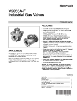
5.2.1 Time chart allowable valve seat leakage rate
This timing chart was developed to meet ANSI Z21.21/CSA 6.5 requirements
0
0 20 40 60 80 100 120 140 160 180
200
5
10
15
20
25
35
30
40
P
inlet
["WC]
(starting pressure)
Minimum time to 50% Pinlet (seconds)
propane
natural gas
ANSI Z21.21/CSA 6.5
This timing chart was developed to meet EN161 requirements.
0
0 50 100 150 200 250 300 350 400 450 500 550
600
5
10
15
20
25
35
30
40
P
inlet
["WC] (starting pressure)
Minimum time to 50% Pinlet (seconds)
propane, 1-1/4" V4730C, V8730C
natural gas, 1-1/4" V4730C, V8730C
propane, other models
natural gas, other models
Specific gravity:
natural gas SG 0.64
propane SG 1.57
EN161

V4730C/V8730C/V4734C · Edition 11.23
EN-7
6 COMMISSIONING
The V4730C/V8730C/V4734C are normally closed
valves. The valves open when energized and close
when power is removed.
WARNING
Explosion and Electrical Shock Hazard. Can cause
severe injury, death or property damage.
Please observe the following:
– Do not put the system into service until you
have satisfactorily completed the Valve Leak
Test, all applicable tests described in the
instructions for the flame safe- guard control,
and any other tests required by the burner
manufacturer.
– All tests must be performed by a trained,
experienced, flame safeguard technician.
– Close all manual fuel shutoff valves immediately
if trouble occurs.
– After the installation is complete, cycle the valve
several times with the manual fuel shutoff valve
cock closed. Make sure the valve functions
properly.
– Also, perform the Valve Leak Test before putting
the valve into service.
6.1 Adjust valve
➔The procedures described in this chapter are
related to the adjustments on the main gas valve.
➔For adjustments on the other additional function-
alities (e.g. pressure switch), refer to the included
instruction sheet of the product in question in the
package.
WARNING
Incorrect installation
Please observe the following to ensure that the
unit is not damaged during adjustment and
operation:
– Adjustments must be made by qualified
personel only.
– To ensure a safe closing of the valves, it is
essential that voltage over the terminals of
operators is reduced to 0 Volts.
2nd valve = fast opening
Flow rate can be adjusted.
Important
➔To ensure a satisfactory setting of the valve the
pressure drop over the valve should be at least
10% of the supply pressure or 2,5mbar which
ever is the greatest.
6.2 Adjust flow rate
2nd valve = fast opening
1 2
3 Turn adjustment screw counter-clockwise to
increase or clockwise to decrease the flow rate.
4 Replace cap on top of the coil.
7 ADJUST SERVO REGULATOR
WARNING
Incorrect adjustment
Please observe the following to ensure that the
unit is not damaged during adjustment and
operation:
– If the appliance manufacturer supplies checkout
and/ or service and maintenance instructions
carefully follow them. If these instructions are
not provided, follow the procedure described
below.
➔In some applications, adjustment screws are
sealed as well, to avoid drift of factory calibration
during transportation. These sealings can be
broken when needed for readjustments, but only
by trained and authorized technicians.
7.1 Adjust gas/air 1:1 regulation
WARNING
Incorrect adjustment
High inlet pressures as used for gas G30 or G31,
can cause oscillation. This is dependent on type of
appliance. If oscillation occurs:
– The oscillation shall not exceed 10 % of the
outlet pressure, with a stable air pressure signal.
– The oscillation has to be verified for the
complete modulation band of the appliance.
– Please contact your Honeywell representative if
the maximum of 10 % is exceeded.
The 1:1 gas/air regulator assembly has an air pres-
sure connection and an offset adjustment screw.
The 1:1 gas/air regulator equals the gas pressure to
the supplied air pressure. With the offset adjustment
screw it is possible to adjust the offset. (Offset =
Pgas - Pair)
3
2
1
1 Cap screw
2 Offset adjustment screw
3 M5 pressure feedback connection
1 With the valve in the final mounting position,
adjust the venturi fan for the lowest burner firing
rate.
2 Remove cap screw with a torque bit (or slotted
screwdriver) to expose offset adjustment screw.
3 Using a torque bit T40 or a 5mm hex wrench,
carefully adjust the low fire gas setting for proper
combustion.
4 After proper low fire offset adjustment has been
made, replace cap screw and tighten pressure
taps.

V4730C/V8730C/V4734C · Edition 11.23
EN-8
5 Before commissioning the burner, check for
proper lightoff and verify correct fuel/air mix and
combustion quality through out the entire firing
range (from lowest to highest fan speeds used).
Checkout of adjustment
6 After any adjustment check pressure taps and
gas connections with an approved leak
detection fluid for gas leakage.
7 After any adjustment set appliance in operation
and observe several complete cycles to ensure
that all burner components function correctly.
7.1.1 Specify application parameters (gas/air
1:1)
Define maximum allowable deviation on ΔPgas
at minimum ΔP air in new appliance for reliability
reasons.
The application parameters can effect the Offset
Adjustment accuracy during cycling and life cycling
of the control system.
These parameters are (in sequence of importance):
– Start pressure (the lower the better)
– Ambient temperature (the lower the better)
It is therefore advisable to verify the offset adjust-
ment at service interval by CO2 measurement or
ΔPgas (burner orifice pressure drop) at minimum
ΔPair (pressure drop over air restriction).
ΔPgas measured on pressure tap of combination
gas control (highest pressure) can deviate from
real ΔP (burner orifice pressure drop) due to gas
turbulence and/or restrictions in the application. The
deviation should be defined and documented. The
measurement accuracy should be +/- 1Pa.
8 MAINTENANCE
WARNING
Explosion hazard and electrical shock hazard!
Can cause severe injury, death of property dam-
age.
– Turn off gas supply and disconnect all electrical
power to the valve before servicing.
– Only trained, experienced, flame safeguard
technicians should attempt to service or repair
flame safeguard controls and burner assem-
blies.
Scheduled Inspection and Maintenance
➔Set up and follow a schedule for periodic inspec-
tion and maintenance, including the burner, all
other controls and the valves.
➔It is recommended that the valve leak test in the
Checkout section be included in this schedule.
Refer to the instructions for the primary safety
control (s) 0 for more inspection and mainte-
nance information.
1 Make sure the gas supply is turned off and all
electrical power has been removed.
2 Remove bolts/nuts from flange/valve.
3 Remove flange from gas supply pipe.
4 Remove old screen/strainer
5 Clean the strainer by using compressed air, or
replace the strainer.
6 Install the cleaned strainer or new strainer.
7 Make sure O-ring sealing surface is clean on the
flange.
8 Using general purpose lithium grease, grease the
Oring.
9 Apply a moderate amount of good quality pipe
dope, resistant to the action of LP gas, only on
the pipe threads.
10 Install the O-ring in the O-ring groove provided
on the flange/valve body (one O-ring per groove).
11 Screw the flange onto the pipe.
12 Mount the gas valve to the flange, using the
bolts and nuts for each flange.
13 Apply power to the valve.
14 Turn on the main gas supply.
15 Complete the valve leak test.
16 Return the valve to service.
9 TROUBLESHOOTING
WARNING
Risk of injury!
Can cause severe injury, death of property dam-
age.
– Use extreme caution when troubleshooting; line
voltage is present.
– Do not replace the valve until all other sources
of trouble are eliminated.
? Fault
! Cause
• Remedy
? The valve does not open when the thermo-
stat or controller calls for heat?
! No voltage at the valve lead wires.
• Check for voltage at the valve lead wires or
terminal block.
! If there is no voltage at the valve lead wires or
terminal block.
• Make sure, that voltage is connected to the
master switch.
• Make sure, that the master switch is closed
and overload protection (circuit breaker, fuse,
or similar device) has not opened the power
line.
! There is still no voltage at the valve lead wires.
• If there is still no voltage at the valve leadwires
or terminal block, make sure all appropriate
contacts in the thermostat or controller, limits
and flame safeguard control are closed. If one
or more are open, determine the cause(s);
correct the trouble and proceed.
! There is proper voltage at the valve but the valve
still does not open.
• check for normal gas pressure.
! Is it not possible for the fault to be eliminated
with the measures described above?

V4730C/V8730C/V4734C · Edition 11.23
EN-9
• Remove the unit and return it to the manufac-
turer for inspection.
? If the valve does not close when one or
more of the appropriate contacts in the
thermostat, controller, limits or flame safe-
guard control is open.
! Is the valve connected in the correct circuit?
• Make sure the valve is wired in the correct
circuit
! Valve is not wired correctly.
• Open the master switch to remove power
from the valve. If the valve closes now, check
the wiring for the valve and correct the wiring
as necessary.
! Is there a short circuit?
• Check for a short in the electrical circuit and
repair it as necessary.
10 ACCESSORIES
10.1 Flange kit
Inlet flanges and outlet flanges are available as
accessories. Valve comes with one kit only.
Scope of delivery:
1 flange with sealing plug,
1 “O”-ring and screws,
1 pressure tap nipple fitted
Flange kits
Part number Size (NPT) Remarks
32006652-001 1/2" pressure tap
1/8"
32006652-002 3/4" pressure tap
1/8"
32006652-003 1” pressure tap
1/8"
32006652-004 1¼” pressure tap
1/8"
10.2 Valve connection plug
Electrical connections Standard DIN plug connector
(black) according DIN43650 (Form A). Not included
in the scope of delivery.
Order No.: CO020012.
10.3 Mixing unit VMU
Integrated gas/air 1:1 with venturi mixing unit, see
instruction sheet VMU "Mixing unit for V473xC/
V8743xC gas controls" (65-0282) www.docuthek.
com.
10.4 Venturi-mounting-kit
For flange mounting the Venturi VMU. Order no.:
32006653-001.
Scope of delivery: O-rings/screws.
10.5 Sensing tube VMU
Short Sensing Tube for VMU150/300/335kW Ven-
turi Mixing Units. Order No.: KTTBA001.
Long Sensing Tube for VMU500kW Venturi Mixing
Unit. Order No.: KTTBA002.
10.6 Manual Shut-Off Valve
Manual Shut-Off Valve Kits can be ordered to pro-
vide manual shut-off function.
Order no.: 50002653-001, for 1inch NPT or smaller
valves.
Order no.: 50002653-002, for 1-1/4inch NPT valve.
10.7 Pressure switch for gas
The pressure switch for gas monitors the inlet pres-
sure or the intermediate pressure.
inlet pressure intermediate pressure
Scope of delivery:
1xpressure switch for gas,
C60VRT4 = UL recognized,
C60VR4 = CE/UKCA certified
2xself-tapping retaining screws,
1xsealing ring,
1xprotection cap.

V4730C/V8730C/V4734C · Edition 11.23
EN-10
10.7.1 Pressure switch connection plug
Electrical connections Standard DIN plug connector
(grey) according DIN43650 (Form A). Not included
in the scope of delivery.
Order No.: CO020014.
10.7.2 Adjust switching point
➔The switching point is adjustable via hand wheel.
1 2 3
Type
Adjusting
range
(adjusting
tolerance =
±15% of the
scale value)
Mean
switching
differential at
min. and max.
setting
[mbar] ["WC] [mbar] ["WC]
C60VRT40040
5–40 2–16 1–2 0,4–1
➔Deviation from the switching point during testing
pursuant to EN1854 Gas pressure switches:
±15%.
11 TECHNICAL DATA
The specifications in this section are related to the
Venturi Mixing Unit (VMU) and Combination Gas
Valve.
Valve and flange size:
Type Valve size Flange size
V4730C1006 1/2" 1/2"
V4730C1014 3/4" 3/4"
V4730C1022 1" 1"
V4730C1030 1" 1 1/4"
V4734C1002 1 1/4" 1 1/4"
V8730C1007 1/2" 1/2"
V8730C1015 3/4" 3/4"
V8730C1023 1" 1"
V8730C1031 1" 1 1/4"
Power consumption:
Type Voltage V1 + V2,
total current
V4730C1006
V4730C1014
120V AC,
50/60Hz 0.26A
V4730C1022
V4730C1030
120V AC,
50/60Hz 0.46A
V4734C1002 120V AC,
50/60Hz
0.8A at
startup
0.26A1)
V8730C1007
V8730C1015
24V AC,
50/60Hz 1.28A
V8730C1023
V8730C1031
24V AC,
50/60Hz 3.0A
1) First value during start up, second value
during normal operation
Capacity:
Type VMU Capacity (natural gas
0.64kg/m3)
V4730C1006 150 22–150kW
(73–512 kBtu/hr)
V4730C1014 185 26–185kW
(89–622 kBtu/hr)
V4730C1022 300 43–300kW
(144-1009 kBtu/hr)
V4730C1022 335 48–335kW
(161-1127 kBtu/hr)
V4730C1030 300 43–300kW
(144–1009 kBtu/hr)
V4730C1030 335 48–335kW
(161–1127 kBtu/hr)
V4734C1002 400 55–382kW
(185–1300 kBtu/hr)
V4734C1002 500 71–500kW
(245–1710 kBtu/hr)
V4734C1002 680 97–680kW
(326–2287 kBtu/hr)
V8730C1007 150 22–150kW
(73–512 kBtu/hr)
V8730C1015 185 26–185kW
(89–622 kBtu/hr)
V8730C1023 300 43–300kW
(144–1009 kBtu/hr)
V8730C1023 335 48–335kW
(161–1127 kBtu/hr)
V8730C1031 300 43–300kW
(144–1009 kBtu/hr)
V8730C1031 335 48–335kW
(161–1127 kBtu/hr)
Maximum operating pressure (UL)
1.45psi (100mbar),
except for 1-1/4inch size:
(24V): 1psi (70mbar),
(120V): 1.45psi (100mbar).
CSA Approved to 0.5psi (34mbar).
Torsion and bending stress
Pipe connections meet group 2 according to
EN13611 requirements.
Electrical connections:
Standard plug connector (according DIN43650)
with 36inch (914mm) lead wires.
Valve position indicator lamps:
Inboard (closest to the valve body) - V1.
Outboard - V2.
Ambient temperature range:
5 to +140°F (-15 to +60°C)
Storage temperature = transport temperature:
-4 to +104°F (-20 to +40°C).
Coil insulation solenoid valves:
Class F insulation system.
Body Material:
Aluminum alloy, die-cast.
Strainer:
Fine mesh screen (0.135 in. [0.34mm] diameter).
AISI 303 steel, serviceable after removing inlet flange
screws. Meets EN161 requirements for strainers.

V4730C/V8730C/V4734C · Edition 11.23
EN-11
Seals and Gaskets:
Hydrocarbon-resistant NBR and Viton rubber types.
Enclosure: NEMA 1 (IP 40)
11.1 Tightening torque
Recommended tightening torques for the connec-
tion parts:
Screw type Tightening torque
Throttle screw
adjustment
max. 4.4 lb-in
min. 0.35 lb-in
Flanges max. 8.8 lb-in
min. 0.04 lb-in
Pressure tap plug 62 ± 8.8 lb-in
Pressure switch
mounting 22 ± 13 lb-in
Pressure switch
cover 10.6 ± 1.8 lb-in
Inlet/outlet flange
screw 38 ± 3.5 lb-in
11.2 Perfomance characteristics
Opening time:
Dead time maximum 1 second.
First valve opening: <0,5 second.
Second valve opening: reaches 50% of the adjusta-
ble outlet pressure within 5 seconds.
Maximum allowable leakage:
Outerwall, safety valve and main valve = 2.5inch3/h
(40 cm3/h for upto DN 25 and 3inch3/h (50 cm3/h)
for DN 32 at test pressure of 0.87psi (6mbar) and
1.5 x maximum operating pressure.
High pressure test:
In the “OFF” condition, the valve will withstand
21.75psi (1.5bar) inlet pressure without damage.
Operational voltage range:
The combination gas valve will function satisfactorily
between 85% and 110% of the rated voltage.
Gas Valve Connection to Venturi (Field-Assembled):
Four screws and an O-ring are used to connect the
gas valve to the venturi/manual shutoff valve.
The metal tube provided with the venturi must be
connected between the venturi and the gas valve
regulator.
Fan Connection:
The venturi is connected to the fan using six bolts
(which are included with VMU).
Minimum Load:
The minimum load for which the system can be
used is 14–17% of the reference load, which equals
a minimum pressure differential of 0.2inch WC
(50Pa) of the 1:1 venturi/servo regulator gas control.
11.3 Hi-lo regulator
Pressure feedback connection:
The high–low regulator with an M5 thread connec-
tion for pressure feedback.
Minimum regulation capacity:
0,31m3/h
Maximum operating pressure:
The maximum pressure Pmax. indication on the
housing of the combination gas control is the maxi-
mum pressure at which it functions safely.
However, the maximum operating pressure is limited
by the pressure range of the high–low pressure reg-
ulator concerned: 50mbar for pressure range 4–37.
Electrical connection:
The high–low coil is provided with an earth terminal.
The high–low coil is provided with quick connect
terminals suitable for 6,3mm.
Connector: DIN43650 From B
Regulator output pressure range:
Pressure
range
(mbar)
Setting
low high
4–37 4 - Pmax (Pmax < Phigh) 12–37
Electrical data:
Supply
voltage
Color of
coil
Current
(mA)
Power
consump-
tion
220/240V~,
50Hz black 17,4/19 3/3,2
12 CERTIFICATION
12.1 Certificate download
Certificates – see www.docuthek.com
12.2 UL recognized
UL429 Electrically operated valves
12.3 ANSI/CSA approved
ANSI Z21.21 and CSA 6.5
13 LOGISTICS
Transport
Protect the unit from external forces (blows, shocks,
vibration).
Transport temperature: see page 10 (11 Technical
data).
Transport is subject to the ambient conditions
described.
Report any transport damage on the unit or packag-
ing without delay.
Check that the delivery is complete.
Storage
Storage temperature: see page 10 (11 Technical
data).
Storage is subject to the ambient conditions
described.
Storage time: 6months in the original packaging
before using for the first time. If stored for longer
than this, the overall service life will be reduced by
the corresponding amount of extra storage time.

V4730C/V8730C/V4734C · Edition 11.23
EN-12
14 DISPOSAL
Devices with electronic components:
WEEE Directive 2012/19/EU – Waste Electrical
and Electronic Equipment Directive
At the end of the product life (number of operat-
ing cycles reached), dispose of the packaging and
product in a corresponding recycling centre. Do not
dispose of the unit with the usual domestic refuse.
Do not burn the product.
On request, old units may be returned carriage paid
to the manufacturer in accordance with the relevant
waste legislation requirements.
© 2023 Honeywell International Inc.
We reserve the right to make technical modifications in the interests of progress.
The Honeywell Thermal Solutions family of products includes
Honeywell Combustion Safety, Eclipse, Exothermics, Hauck,
Kromschröder and Maxon. To learn more about our products, visit
ThermalSolutions.honeywell.com or contact your Honeywell Sales
Engineer.
Honeywell Thermal Solutions (HTS)
2101 CityWest Blvd
Houston, TX 77042
United States
ThermalSolutions.honeywell.com
FOR MORE INFORMATION
/