Page is loading ...

INSTALLATION, OPERATION & MAINTENANCE MANUAL
ENERGY RECOVERY VENTILATOR
HE6X
RENEWAIRE.COM
MODEL: HE6XIN

RENEWAIRE.COM INSTALLATION, OPERATION AND MAINTENANCE MANUAL 1.800.627.44992
HE6X info ............................. 2-6
Installation ..........................7-14
Start-up & Operation .........15-18
Maintenance .....................20-23
TABLE OF CONTENTS
HE6X INFO
HE6X CONFIGURATION CHART
MODEL NUMBER
"V", "H" (Indoor Units)
"V", "H", "R", "F" (Rooftop
Units)
1 2 3 4 5 6 7 8 9 10 11 12 13 14 15 16 17 18 19 20 21 22 23 24 25
J - - -
DIGIT NUMBER
Location
Digits 7 - 8:
"IN" = Indoor
"RT" = Rooftop
Orientation
Digit 9:
Wall Type
Digit 11:
"S" = Single
"D" = Double
Phase
Digit 12:
"3" = Three Phase
Voltage
Digit 13:
"4" = 460V
"5" = 208-230V
"8" = 575V
FA Horsepower
Digit 14:
"X" = 5HP
"Y" = 7.5HP
Flow Control*
Digit 18:
"-" = No Isolation Dampers (with no Bypass)
"D" = Motorized Damper both Airstreams (with no Bypass)
"E" = Motorized Damper EA or RA Airstream (with no Bypass)
"F" = Motorized Damper FA or OA Airstream (with no Bypass)
"0" = Drybulb Bypass Dampers only (no Isolation Dampers)
"1" = Drybulb Bypass with Motorized Dampers all Airstreams
"4" = Drybulb Bypass with Motorized Damper OA Airstream
"5" = Enthalpy Bypass Dampers only (no Isolation Dampers)
"6' = Enthalpy Bypass with Motorized Dampers all Airstreams
"9" = Enthalpy Bypass witih Motorized Damper OA Airstream
*NOTES:
Digit 6 "J" = G5 Core Type Digits 10, 16 and 17 are not used in these models.
*Digit 18: Flow Control: Codes for Bypass: Face damper also acts as Isolation damper in EA or RA Airstream.
Restrictions:
1: Bypass only available with Location Code "IN".
Unit Control
Digit 19:
"A" = Standard Unit Control Wiring
"V" = Onboard VFD Both Airstreams
"F" = Onboard VFD FA Airstream
"E" = Onboard VFD EA Airstream
Disconnect
Digit 20:
"N" = Non-Fused (STANDARD)
"F" = Fused
Unit Control Enhancements
Digit 21:
"T" = Transformer with Isolation Relay (STANDARD)
"1" = Enhanced Controls
"2" = Premium Controls
"3" = Enhanced Controls with BACNET License
"4" = Premium Controls with BACNET License
Filter Options
Digit 22:
"-" = None
"F" = Filter Monitor Both Airstreams
Other Options
Digit 23:
"-" = None (Reserved)
Paint and Customization
Digit 24:
"-" = None
"W" = White Paint
"C" = Custom Paint
"X" = Custom Unit
Safety Listing
Digit 25:
"N" = Non-Listed
-HE - 6X
EA Horsepower
Digit 15:
"X" = 5HP
"Y" = 7.5HP
HE6X MODEL
PRODUCT CODE CHART
NOTE: RenewAire reserves the right to make changes in the design or specifications of products at any time without notice. Unless otherwise
specified, dimensions are rounded to the nearest eighth of an inch.
ERV HE6X

3 1.800.627.4499 INSTALLATION, OPERATION AND MAINTENANCE MANUAL RENEWAIRE.COM
Specifications may be subject to change without notice.
RENEWAIRE.COM 1.800.627.4499
88
SPECIFICATIONS & DIMENSIONS
Specifications may be subject to change without notice.
INDOOR UNIT
Ventilation Type:
Static plate, heat and humidity transfer
Typical Airflow Range: 1,500-6,500 CFM
AHRI 1060 Certified Core:
Six L125-G5
Standard Features:
TEFC Premium efficiency motors
Motor starters
Non-fused disconnect
24 VAC transformer/relay package
Filters:
Total qty. 12, MERV 8: 20" x 20" x 2"
Unit Dimensions & Weight:
88" L x 113 1/2" W x 81 3/4" H
2,235-3,099 lbs., varies by option(s)
Max. Shipping Dimensions & Weight (on pallet):
116" L x 90" W x 90" H
3,439 lbs.
Motor(s):
Qty. 2, Belt drive blower/standard motor packages
with adjustable sheaves (see table below)
Options:
Integrated programmable controls
Fused disconnect
Double wall construction
Factory supplied and mounted variable frequency
drives (VFDs) - one or both airstreams
Shaft grounding ring on motors with VFDs
Class 1 low leakage motorized isolation dampers -
OA, EA or both airstreams
Qty. 2, Factory mounted filter alarms
Exterior paint - white, custom colors
Bypass economizer (see bypass DIM drawing) -
dry-bulb temperature controls (standard),
enthalpy controls (option)
Accessories:
Filters - MERV 13, 2" (shipped loose)
Digital time clock - wall mount (TC7D-W),
in exterior enclosure (TC7D-E)
Motion occupancy control - ceiling mount (MC-C),
wall mount (MC-W)
Carbon dioxide control - wall mount (CO2-W),
duct mount (CO2-D)
Electric duct heater - EK series (1–60 kW),
EH series (61–175 kW)
Indirect gas-fired duct furnace - GH series
(50-400 MBH), installed downstream of any fans
ELECTRICAL DATA
Standard Electrical Specifications Optional Factory Installed
VFD Electrical Specifications
HP Volts HZ Phase FLA
per motor
Min. Cir.
Amps
Max.
Overcurrent
Protection
Device
FLA per
motor
Min. Cir.
Amps
Max.
Overcurrent
Protection
Device
5.0
208-230
460
575
60
60
60
Three
Three
Three
14.5-13.4
6.7
5.3
32.6
15.1
11.9
45
20
15
14.5-13.4
6.7
5.3
35.9
16.6
13.1
45
20
15
7.5
208-230
460
575
60
60
60
Three
Three
Three
21.0-19.0
9.5
7.6
47.3
21.4
17.1
60
25
20
21.0-19.0
9.5
7.6
52.0
23.5
18.8
60
25
20
SPECIFICATIONS
For safety listed products,
see LE-SERIES models.
CORE PERFORMANCE
ThermalPerformanceRatingsG52015.2.xlsx 6Cores(IOM)
30%
50%
70%
90%
1000 2000 3000 4000 5000 6000 7000
Effectiveness (%)
Airflow (CFM)
At AHRI 1060 standard conditions.
See all AHRI certified ratings at www.ahrinet.org.
Motor
HP
Blower
RPM
Sheave
Adj.
Turns
Open
External Static Pressure (in. w.g.)
0.00 0.25 0.50 0.75 1.00 1.25 1.50 1.75 2.00
CFM BHP CFM BHP CFM BHP CFM BHP CFM BHP CFM BHP CFM BHP CFM BHP CFM BHP
5.0
1460 4.5 5005 3.2 4800 3.2 4650 3.1 4475 3.0 4200 2.9 4000 2.8 3750 2.8 3400 2.7 3100 2.5
1610 2 5550 4.2 5375 4.2 5250 4.1 5100 4.1 4900 4.0 4650 3.9 4500 3.8 4250 3.7 4000 3.6
1725 0 5525 5.0 5475 5.0 5200 4.9 5050 4.8 4800 4.6 4600 4.5
7.5
1560 4.5 5275 3.7 5200 3.6 4900 3.5 4775 3.5 4550 3.4 4350 3.3 4125 3.3 3875 3.2 3575 3.1
1740 2 5950 5.0 5825 5.0 5625 4.9 5490 4.9 5325 4.8 5125 4.7 4950 4.7 4750 4.6 4525 4.5
1865 0 6500 6.5 6350 6.5 6225 6.4 6125 6.4 5910 6.3 5825 6.2 5625 6.1 5410 6.1 5300 6.0
AIRFLOW PERFORMANCE
Note: Airflow performance includes effect of clean, standard filter supplied with unit.
Note: Brake Horse Power (BHP) is for one blower motor package only. Operation in this zone will likely exceed FLA limits.
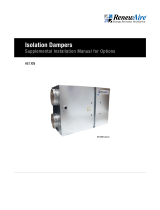
6XINHE Energy Recovery Ventilator
Standard & Bypass Economizer Option
HE
Download specification at:
renewaire.com/specifications
Specifications may be subject to change without notice.

RENEWAIRE.COM INSTALLATION, OPERATION AND MAINTENANCE MANUAL 1.800.627.44994
Specifications may be subject to change without notice.
FOR THE MOST COMPLETE AND CURRENT INFORMATION VISIT RENEWAIRE.COM
HE-SERIES
89
86 3/4" Overall
75 7/8" Lift Lugs
81"
FRONT VIEW
63 1/4"
31 3/4"
108"
INDOOR UNITS: EA BLOWER Outlet is
16" X 22" (Nom.) 24"X36"
Duct Receiving Flange is also supplied.
Field install only in location shown.
RIGHT VIEW
Internal EA Motorized
Damper Location (Optional)
10 1/4"
63 1/4"
78 1/4" Case
2 1/4"
102 7/8" Lift Lugs
81 5/8" Overall
FA Blower Outlet is 16" X 22" (Nom.)
24"X36" Duct Receiving Flange is
also supplied. Field install only in
location shown.
Core
Access
Door
LEFT VIEW
Pressure
Ports
(4) Typ.
22" Typ.
8 3/4"
49 5/8"
85 5/8" Case
BACK VIEW
24" X 36"
Duct Receiving
FlangeTyp.
Internal OA Damper
Location (Optional)
112 5/8"
Case
113 1/8"
Overall
39 1/4"
Minimum
Service
Area
36"
69 1/4"
62"
34 3/4"
Minimum
Service
Area
34 3/4"
Minimum
Service Area
85 5/8"
Minimum
Service Area
TOP VIEW
E-Box
Minimum
Service Area
FA
EA
RA
OA
Door
Swing
Door
Swing
Door
Swing
Power and Control Wiring
Entries 7/8" Dia.
Model: HE6XIN
Drawing Type: Unit Dimension
Version: FEB18
ABBREVIATIONS
EA: Exhaust Air to outside
OA: Outside Air intake
RA: Room Air to be exhausted
FA: Fresh Air to inside
INSTALLATION ORIENTATION
Unit must be installed in orientation
shown.
NOTE
1.ALL UNITS HAVE INTERNAL EA
BACKDRAFT DAMPER.
UNLESS AN EA MOTORIZED ISOLATION
DAMPER IS SPECIFIED.
2.UNLESS OTHERWISE SPECIFIED,
DIMENSIONS ARE ROUNDED TO THE
NEAREST EIGHTH OF AN INCH.
3.SPECIFICATIONS MAY BE SUBJECT
TO CHANGE WITHOUT NOTICE.
HE6X
IN
Energy Recovery Ventilator
Standard
AIRFLOW CONFIGURATION
Available as shown in dimension drawing.
UNIT MOUNTING & APPLICATION
Must be mounted as shown. Airstreams can not
be switched.

5 1.800.627.4499 INSTALLATION, OPERATION AND MAINTENANCE MANUAL RENEWAIRE.COM
RENEWAIRE.COM 1.800.627.4499
90
SPECIFICATIONS & DIMENSIONS
Specifications may be subject to change without notice.
ROOFTOP UNIT
Ventilation Type:
Static plate, heat and humidity transfer
Typical Airflow Range: 1,500-6,500 CFM
AHRI 1060 Certified Core:
Six L125-G5
Standard Features:
TEFC Premium efficiency motors
Motor starters
Non-fused disconnect
24 VAC transformer/relay package
Filters:
Total qty. 12, MERV 8: 20" x 20" x 2"
Unit Dimensions & Weight:
106 1/2" L x 113 1/2" W x 81 3/4" H
2,301-3,166 lbs., varies by option(s)
Max. Shipping Dimensions & Weight (on pallet):
116" L x 90" W x 90" H
3,599 lbs.
Motor(s):
Qty. 2, Belt drive blower/standard motor packages
with adjustable sheaves (see table below)
ELECTRICAL DATA
Standard Electrical Specifications Optional Factory Installed
VFD Electrical Specifications
HP Volts HZ Phase FLA
per motor
Min. Cir.
Amps
Max.
Overcurrent
Protection
Device
FLA
per motor
Min. Cir.
Amps
Max.
Overcurrent
Protection
Device
5.0
208-230
460
575
60
60
60
Three
Three
Three
14.5-13.4
6.7
5.3
32.6
15.1
11.9
45
20
15
14.5-13.4
6.7
5.3
35.9
16.6
13.1
45
20
15
7.5
208-230
460
575
60
60
60
Three
Three
Three
21.0-19.0
9.5
7.6
47.3
21.4
17.1
60
25
20
21.0-19.0
9.5
7.6
52.0
23.5
18.8
60
25
20
SPECIFICATIONS
Note: Brake Horse Power (BHP) is for one blower motor package only. Operation in this zone will likely exceed FLA limits.
AIRFLOW PERFORMANCE
Motor HP Blower
RPM
Sheave
Adj.
Turns
Open
External Static Pressure (in. w.g.)
0.00 0.25 0.50 0.75 1.00 1.25 1.50 1.75 2.00
CFM BHP CFM BHP CFM BHP CFM BHP CFM BHP CFM BHP CFM BHP CFM BHP CFM BHP
5.0
1460 4.5 5005 3.2 4800 3.2 4650 3.1 4475 3.0 4200 2.9 4000 2.8 3750 2.8 3400 2.7 3100 2.5
1610 2 5550 4.2 5375 4.2 5250 4.1 5100 4.1 4900 4.0 4650 3.9 4500 3.8 4250 3.7 4000 3.6
1725 0 5525 5.0 5475 5.0 5200 4.9 5050 4.8 4800 4.6 4600 4.5
7.5
1560 4.5 5275 3.7 5200 3.6 4900 3.5 4775 3.5 4550 3.4 4350 3.3 4125 3.3 3875 3.2 3575 3.1
1740 2 5950 5.0 5825 5.0 5625 4.9 5490 4.9 5325 4.8 5125 4.7 4950 4.7 4750 4.6 4525 4.5
1865 0 6500 6.5 6350 6.5 6225 6.4 6125 6.4 5910 6.3 5825 6.2 5625 6.1 5410 6.1 5300 6.0
Note: Airflow performance includes effect of clean, standard filter supplied with unit.
CORE PERFORMANCE
ThermalPerformanceRatingsG52015.2.xlsx 6Cores(IOM)
30%
50%
70%
90%
1000 2000 3000 4000 5000 6000 7000
Effectiveness (%)
Airflow (CFM)
At AHRI 1060 standard conditions.
See all AHRI certified ratings at www.ahrinet.org.
Options:
Integrated programmable controls
Fused disconnect
Double wall construction
Factory supplied and mounted variable frequency
drives (VFDs) - one or both airstreams
Shaft grounding ring on motors with VFDs
Class 1 low leakage motorized isolation dampers -
OA, EA or both airstreams
Qty. 2, Factory mounted filter alarms
Exterior paint - white, custom colors
Accessories:
Filters - MERV 13, 2" (shipped loose)
Roof curb - standard 14"
Curb wind clip
Engineered combo curb for Carrier RTU
Engineered combo curb for Trane RTU
Digital time clock - wall mount (TC7D-W),
in exterior enclosure (TC7D-E)
Motion occupancy control - ceiling mount (MC-C),
wall mount (MC-W)
Carbon dioxide control - wall mount (CO2-W),
duct mount (CO2-D)
Electric duct heater - EK series (1–60 kW),
EH series (61–175 kW); designed for indoor
ductwork installation only
Indirect gas-fired duct furnace - GH series
(50-400 MBH), installed downstream of any fans
6XRTHE Energy Recovery Ventilator
Standard
HE
Download specification at:
renewaire.com/specifications
For safety listed products,
see LE-SERIES models.

RENEWAIRE.COM INSTALLATION, OPERATION AND MAINTENANCE MANUAL 1.800.627.44996 RENEWAIRE.COM INSTALLATION, OPERATION AND MAINTENANCE MANUAL 1.800.627.44996
FOR THE MOST COMPLETE AND CURRENT INFORMATION VISIT RENEWAIRE.COM
HE-SERIES
91
10 1/4"
30 1/2"
102 7/8"
Lifting Lugs
109 1/2" Case
1 1/4"
Typ.
113 1/8" Overall
FRONT VIEW
FA
RTV, RTF
ONLY
RA
RTV, RTR
ONLY
RTH, RTF
ONLY
RA
FA Outlet
(RTH, RTR)
15 7/8" X 21 3/4"
Duct Receiving
Flange
OA
EA Outlet
Pressure
Ports
(4) Typ.
79 5/8" Case
83" Case
106 1/4" Overall
81 5/8" Overall
RIGHT VIEW
Disconnect
Switch
Power/Control
Wiring Entries
7/8 Typ.
EA
22"
9 3/8"
LEFT VIEW
EA
FA
RTH, RTR
ONLY
OA Damper
Location
(Optional)
EA Damper
Location
(Optional)
OA Inlet
Louver
RA Inlet
(RTH, RTF)
24" X 36"
Duct Receiving
Flange
60 7/8"
19 7/8"
71 1/2"
54 7/8"
65 3/4" Minimum
Service Area
121 1/4" Minimum
Service Area
20" Minimum
Service Area
15 3/4"
26 1/4"
135 3/4" Minimum
Service Area
39 1/2"
FA (RTV, RTF)
16" X 22"
RA (RTV, RTR)
24" X 34"
Door
Swing
Door
Swing
Door
Swing
TOP VIEW
99 1/4" I.D.
36"
26" 26" 31"
103" O.D.
36"
72 1/4" I.D.
76" O.D.
A
A
TOP VIEW
CURB 6X
RA
FA
1 7/8"
3"
14"
SECTION A-A
CURB CROSS-SECTION A-A (TYP.)
1 1/2" X 1/4"
Neoprene Gasket
3/4" X 3 1/2"
Wooden Nailer
Model: HE6XRT
Drawing Type: Unit Dimension
Version: FEB18
ABBREVIATIONS
EA: Exhaust Air to outside
OA: Outside Air intake
RA: Room Air to be exhausted
FA: Fresh Air to inside
RTV: Rooftop Vertical RA & FA
RTF: Rooftop Vertical FA Only
RTR: Rooftop Vertical RA Only
RTH: Rooftop Horizontal RA & FA
INSTALLATION ORIENTATION
Unit must be installed in orientation
shown.
NOTE:
1. UNLESS OTHERWISE SPECIFIED,
DIMENSIONS ARE ROUNDED TO THE
NEAREST EIGHTH OF AN INCH.
2. SPECIFICATIONS MAY BE SUBJECT
TO CHANGE WITHOUT NOTICE.
HE6X
RT
Energy Recovery Ventilator
Standard
AIRFLOW CONFIGURATION
Available as shown:
UNIT MOUNTING & APPLICATION
Must be mounted as shown. Airstreams can not
be switched.
AF
AR
OA EA
BACK
HE6XRT, HE8XRT
RTV
EA
BACK
AF
RA
OA
HE6XRT, HE8XRT
RTF
FA
RA
OA EA
BACK
FRONT
HE6XRT, HE8XRT
RTH
EA
BACK
AR
FRONT
OA
FA
HE6XRT, HE8XRT
RTR
Options:
Integrated programmable controls
Fused disconnect
Double wall construction
Factory supplied and mounted variable frequency
drives (VFDs) - one or both airstreams
Shaft grounding ring on motors with VFDs
Class 1 low leakage motorized isolation dampers -
OA, EA or both airstreams
Qty. 2, Factory mounted filter alarms
Exterior paint - white, custom colors
Accessories:
Filters - MERV 13, 2" (shipped loose)
Roof curb - standard 14"
Curb wind clip
Engineered combo curb for Carrier RTU
Engineered combo curb for Trane RTU
Digital time clock - wall mount (TC7D-W),
in exterior enclosure (TC7D-E)
Motion occupancy control - ceiling mount (MC-C),
wall mount (MC-W)
Carbon dioxide control - wall mount (CO2-W),
duct mount (CO2-D)
Electric duct heater - EK series (1–60 kW),
EH series (61–175 kW); designed for indoor
ductwork installation only
Indirect gas-fired duct furnace - GH series
(50-400 MBH), installed downstream of any fans
Specifications may be subject to change without notice.

ERVHE6X
7 1.800.627.4499 INSTALLATION, OPERATION AND MAINTENANCE MANUAL RENEWAIRE.COM 7 1.800.627.4499 INSTALLATION, OPERATION AND MAINTENANCE MANUAL RENEWAIRE.COM
PLANNING
YOUR INSTALLATION
INSTALLATION
BASIC ORDER OF
INSTALLATION
1. Prepare roof curb or
equipment rail.
2. Lift unit into position on curb
or rail.
3. Secure unit to curb or rail.
4. Install exhaust hood if
applicable.
5. Install external ductwork if
applicable.
6. Make electrical connections.
7. Perform start-up and check-
out procedures.
Air leakage from the conditioned
space below the roof into the
space between inside the curb
can cause problems including:
• Condensation inside the
curb in cold weather, to
the point that water drips
into the building and
damages duct insulation or
furnishings.
• Leakage of noise from the
unit into the space below.
Holes through the roof deck for
the ducts should be cut close to
the ducts and the gaps should be
sealed.
CAUTION
ERVHE6X
7 1.800.627.4499 INSTALLATION, OPERATION AND MAINTENANCE MANUAL RENEWAIRE.COM
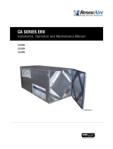
STEP 2: LIFT UNIT INTO POSITION ON CURB OR RAIL
Remove the shipping straps that hold the unit to its pallet before lifting. For Rooftop units, do not install
outside air inlet hoods before lifting unit
102-3/4"
76-3/4"
B
NOTICE TO RIGGERS
USE SPREADER BARS!
CORE ACCESS
DOOR
BLOWER ACCESS
DOORS
37-1/4
2760(2) 7.5HP
(2) 5HP 2659
DOUBLE WALL
44-3/4
46
HE6XIN UNIT CENTER OF GRAVITY (in)
AWEIGHTHP
(2) 5HP
(2) 7.5HP
2235 37-3/4
2336
SINGLE WALL
AND WEIGHT (POUNDS)
B
45-1/4
44
A
STEP 1: PREPARE ROOF CURB OR EQUIPMENT RAIL
Complete the installation of the curb or equipment rail before installing the unit.
Curbs or equipment rails should be attached to the structure sufficiently to transfer wind loads on the unit to
the structure itself. See warning under Step 3.
Curbs or equipment rails should be installed where the structure is able to carry the weight of the unit.
Dimensioned drawings of RenewAire’s standard roof curbs are available at www.renewaire.com.
On Roof Curbs:
Curb should be insulated. Apply roofing and counterflashing to curb as per standard practice.
Install appropriate gasket on top of Roof Curb around the perimeter and around the edges of ducts.
If unit is ducted through the curb the ducts should be installed before the unit is placed on the curb.
Ducts should be insulated.
Vibration Isolation Curbs: Corner weights are available for design purposes at www.renewaire.com.
On Equipment Rails:
Before installing the unit, apply roofing and counterflashing to Equipment Rails as per standard practice.
Risk of severe injury or death
when unit is being lifted! Lifting
must be performed by qualified
personnel only!
F1

ERV HE6X
RENEWAIRE.COM INSTALLATION, OPERATION AND MAINTENANCE MANUAL 1.800.627.44998
CORNER
WEIGHTS F2
INSTALLATION
4/19/07 MF
SPECIFICATIONS SUBJECT
TO CHANGE WITHOUT NOTICE.
CORNER WEIGHTS MAY NOT ADD UP
EXACTLY TO UNIT WEIGHT
DUE TO ROUNDING.
RenewAire LLC
Scale: 1" = 32"
Do not scale drawing
HE6XIN_CORNER_WEIGHTS_APR07.dwg
HE6XIN Corner Weights
Top View
2235(2) 5HP
2336(2) 7.5HP
HP & PHASE UNIT LF LR RR RF
BY HORSEPOWER
HE6XIN UNIT AND CORNER WEIGHTS (LBS)
INDICATES LOCATIONS AT WHICH CORNER
WEIGHTS ARE CALCULATED: ALONG
OUTSIDE CORNERS OF BASE RAILS.
LR RR
101.125"
74.125"
RFLF
UNIT COG
RANGE
SINGLE WALL
(2) 5HP
(2) 7.5HP
7412659
2760 783
DOUBLE WALL
608
616
586
594
724
767
507662
622 498
665502
493 622
HE6XIN UNIT CORNER WEIGHTS (LBS.)
SINGLE-WALL
HP & PHASE UNIT LF LR RR RF
(2) 5HP 2235 622 498 493 622
(2) 7.5HP 2336 662 507 502 665
DOUBLE-WALL
HP & PHASE UNIT LF LR RR RF
(2) 5HP 2659 741 608 586 724
(2) 7.5HP 2760 783 616 594 767
HE6XRT UNIT CORNER WEIGHTS (LBS.)
SINGLE-WALL
HP & PHASE UNIT LF LR RR RF
(2) 5HP 2301 617 518 532 634
(2) 7.5HP 2402 660 525 539 677
DOUBLE-WALL
HP & PHASE UNIT LF LR RR RF
(2) 5HP 2726 739 628 624 734
(2) 7.5HP 2827 782 635 631 778
±INDICATES LOCATIONS AT WHICH CORNER WEIGHTS ARE
CALCULATED ALONG CENTERS OF CURB RAILS.
F3
10 1/4"
30 1/2"
102 7/8"
Lifting Lugs
109 1/2" Case
1 1/4"
Typ.
113 1/8" Overall
FRONT VIEW
FA
RTV, RTF
ONLY
RA
RTV, RTR
ONLY
RTH, RTF
ONLY
RA
FA Outlet
(RTH, RTR)
15 7/8" X 21 3/4"
Duct Receiving
Flange
OA
EA Outlet
Pressure
Ports
(4) Typ.
79 5/8" Case
83" Case
106 1/4" Overall
81 5/8" Overall
RIGHT VIEW
Disconnect
Switch
Power/Control
Wiring Entries
7/8 Typ.
EA
22"
9 3/8"
LEFT VIEW
EA
FA
RTH, RTR
ONLY
OA Damper
Location
(Optional)
EA Damper
Location
(Optional)
OA Inlet
Louver
RA Inlet
(RTH, RTF)
24" X 36"
Duct Receiving
Flange
60 7/8"
19 7/8"
71 1/2"
54 7/8"
65 3/4" Minimum
Service Area
121 1/4" Minimum
Service Area
20" Minimum
Service Area
15 3/4"
26 1/4"
135 3/4" Minimum
Service Area
39 1/2"
FA (RTV, RTF)
16" X 22"
RA (RTV, RTR)
24" X 34"
Door
Swing
Door
Swing
Door
Swing
TOP VIEW
99 1/4" I.D.
36"
26" 26" 31"
103" O.D.
36"
72 1/4" I.D.
76" O.D.
A
A
TOP VIEW
CURB 6X
RA
FA
1 7/8"
3"
14"
SECTION A-A
CURB CROSS-SECTION A-A (TYP.)
1 1/2" X 1/4"
Neoprene Gasket
3/4" X 3 1/2"
Wooden Nailer
Model: HE6XRT
Drawing Type: Unit Dimension
Version: FEB18
ABBREVIATIONS
EA: Exhaust Air to outside
OA: Outside Air intake
RA: Room Air to be exhausted
FA: Fresh Air to inside
RTV: Rooftop Vertical RA & FA
RTF: Rooftop Vertical FA Only
RTR: Rooftop Vertical RA Only
RTH: Rooftop Horizontal RA & FA
INSTALLATION ORIENTATION
Unit must be installed in orientation
shown.
NOTE:
1. UNLESS OTHERWISE SPECIFIED,
DIMENSIONS ARE ROUNDED TO THE
NEAREST EIGHTH OF AN INCH.
2. SPECIFICATIONS MAY BE SUBJECT
TO CHANGE WITHOUT NOTICE.

ERVHE6X
9 1.800.627.4499 INSTALLATION, OPERATION AND MAINTENANCE MANUAL RENEWAIRE.COM
INSTALLATION
STEP 3: SECURE UNIT TO CURB OR RAIL
RenewAire strongly recommends that you secure rooftop units properly to the curb or equipment rails, and
thus to the building structure. Strong winds, tornados, and hurricanes can and do displace or remove rooftop
equipment from rails or curbs. When this happens, the equipment, adjacent roof structure, and even vehicles
parked near the building can be damaged, and rain typically enters the building. The equipment is put out of
service and the collateral damage can be very expensive.
At a minimum, observe locally applicable codes, but note that even if local codes require some attachment
means that may not be enough to withstand common wind occurrences.
STEP 4: INSTALL EXHAUST AIR HOOD (ROOFTOP UNITS ONLY)
To Install the Exhaust Air Hood:
Exhaust Air Hood is shipped in the Exhaust Air Blower compartment, along with a bag of screws. Install Hood
over exhaust air outlet using pre-drilled holes.
STEP 5: INSTALL EXTERNAL DUCTWORK (IF APPLICABLE)
Rooftop units:
Any exposed ductwork attached to the unit must be properly insulated and weatherproofed.
Units ordered in RTH, RTR or RTF configurations have side openings for connection of ductwork.
Room Air (air returning to the unit to be exhausted):
Units are shipped with 24” wide by 36” high duct flanges installed.
Fresh Air (air leaving the unit to be ducted into the building):
24” x 36” duct flanges are shipped loose. For best airflow performance, install this duct flange even with the
bottom of the Fresh Air blower outlet, and centered side-to-side.
Alternately, duct flanges as small as 18” x 24” (the blower outlet size) can be used along with transitions to
the final duct size.
Indoor units:
Ducts between the unit and the outside air must be insulated. See caution to right.
Select locations for the outside air intake weatherhood and exhaust weatherhood carefully. See caution to right.
Outside Wall Caps:
Wall caps should be designed to exclude animals and rain. Size wall caps to minimize pressure drop.
To keep rain out, select the outside air intake weatherhood so inlet velocity is below 500 feet per minute (or
less, if so dictated by local codes or practices).
Install catches for rubber Door Restraints:
Doors for the Fresh Air Blower and the Core and Filter compartments are equipped with rubber Door Restraints.
For units with a Fresh Air Outlet duct fitted to the side, the catches for these Door Restraints are mounted on
the duct.
Tape both inner and outer vapor
barriers of insulated duct to
collars on duct adapters. This is
critical to prevent migration of
moisture into insulation. Build-up
of moisture can result in failure
of the duct system and/or frost
in the insulation. Make sure any
tears in the inner and outer vapor
barriers are sealed.
CAUTION
The unit’s fresh air inlet should be at least 10' away from any exhaust, such as dryer vents, chimneys,
furnace and water heater exhausts, or other sources of contamination or carbon monoxide. Do not locate the
fresh air inlet where vehicles may be serviced or left idling. Never locate the unit inside a structure.
Danger of damage or severe injury if high winds move this unit. Secure unit to structure. Observe local code
requirements at a minimum.
WARNING

ERV HE6X
RENEWAIRE.COM INSTALLATION, OPERATION AND MAINTENANCE MANUAL 1.800.627.449910
INSTALLATION
GENERAL PRACTICES
Take these simple steps to attenuate noise from the unit.
Outside the building:
The exhaust hood is the primary source of noise
outside the building. When practical, orient the exhaust
air hood to point away from houses or public areas.
At the Curb:
Cut the holes in the roof deck to fit closely around
the duct(s) passing through the roof deck. Seal all
gaps around the duct(s) at the roof deck.
Ducts:
Make sure the ductwork at the unit outlets is stiff
enough to resist the flexure and resulting booming
associated with system start-up and shut-off, as well
as the turbulent flow conditions at the blower outlets.
In general, provide smooth transitions from the ERV’s
outlets to the duct. The ducts connecting to the
outlets should be straight for a sufficient distance,
with gradual transitions to the final duct size.
These guidelines are consistent with SMACNA
recommended duct layout practices for efficient
and quiet air movement. Follow SMACNA guidelines.
RADIATED NOISE
The HE6X is insulated with high-density fiberglass.
This provides significant attenuation of radiated
sound from the unit itself.
The outlet ducts can be significant sources of radiated
sound as well. The FA duct should be insulated for
sound control. This insulation should start at the unit.
At a minimum the first ten feet of duct should be
insulated. All parts of the FA and RA ducts located in
a mechanical space with noise-generating equipment
also should be insulated for sound control, both to
minimize sound radiation out of the FA duct, and also
to control sound radiation into both ducts.
AERODYNAMIC (VELOCITY) NOISE
When sound attenuation is a design concern, the
primary consideration is velocity noise at the unit’s
Fresh Air blower outlet. The average velocity at
the Fresh Air blower outlet is 1090 when the unit
is operating at 6500 CFM. The average velocity at
the Exhaust Hood outlet is 1765 FPM when the unit
is operating at 6500 CFM.
PLANNING
YOUR INSTALLATION
To avoid motor bearing damage
and noisy and/or unbalanced
impellers, keep drywall spray,
construction dust, etc., out of unit.
CAUTION
1. Before servicing or cleaning the unit, switch
power off at disconnect switch or service panel
and lock-out/tag-out to prevent power from
being switched on accidentally. More than
one disconnect switch may be required to de-
energize the equipment for servicing.
2. This installation manual shows the suggested
installation method. Additional measures may
be required by local codes and standards.
3. Installation work and electrical wiring must be
done by qualified professional(s) in accordance
with all applicable codes, standards and
licensing requirements.
4. Any structural alterations necessary
for installation must comply with all
applicable building, health, and safety code
requirements.
5. This unit must be grounded.
6. Danger of severe injury to bystanders and
damage to unit or property if high winds move
this unit. Secure this unit to the building!
7. Sufficient air is needed for proper combustion
and exhausting of gases through the flue
(chimney) of fuel burning equipment that
might be installed in the area affected by this
equipment. If this unit is exhausting air from a
space in which chimney-vented fuel burning
equipment is located, take steps to assure that
combustion air supply is not affected. Follow the
heating equipment manufacturer’s requirements
and the combustion air supply requirements of
applicable codes and standards.
8. Use the unit only in the manner intended by the
manufacturer. If you have questions, contact
the manufacturer.
9. This unit is intended for general ventilating only. Do
not use to exhaust hazardous or explosive materials
and vapors. Do not connect this unit to range hoods,
fume hoods or collection systems for toxics.
10. When cutting or drilling into wall or ceiling,
do not damage electrical wiring and other
hidden utilities.
11. If installed indoors this unit must be properly
ducted to the outdoors.
RISK OF FIRE, ELECTRIC SHOCK, OR INJURY. OBSERVE ALL CODES AND THE FOLLOWING:
WARNING
Do not remove or disable the
wiring interconnection between
the Overload Relays and the
Contactors. Without this inter-
connection the motor(s) will not
be protected against overload.
CAUTION
SOUND
ATTENUATION

ERVHE6X
11 1.800.627.4499 INSTALLATION, OPERATION AND MAINTENANCE MANUAL RENEWAIRE.COM
INSTALLATION
HE6X P3 IBC THREE PHASE UNIT WITH INDEPENDENT BLOWER CONTROL
Schematics shown are representative of standard units. See Unit Schematic label for detailed information.
WIRING SCHEMATICS
TRANSFORMER
with Circuit Breaker
TRANSFORMER
with Circuit Breaker
24VAC 24VAC
1L1 2T1
3L2 4T2
5L3 6T3
96 95
C
A2
A1
MOTOR STARTER (EA)
24VAC
1L1 2T1
3L2 4T2
5L3 6T3
96 95
C
A2
A1
MOTOR STARTER (FA)
MOTOR
FA
MOTOR
EA
T1
L2 T2
L3 T3
L1
FUSES (opt.)
UNIT DISCONNECT
14
35
C
RELAY (FA)
14
35
C
RELAY (EA)
"UNIT CONTROL USING CLASS II 24VACPOWER PROVIDED BY THIS UNIT"
24VAC POWER AVAILABLE AT TERMINALS 1 & 2
INSTALL PROVIDED JUMPER BETWEEN TERMINALS 2 & 3
FACTORY SETTINGS:
Overload Relay Trip Settings = Motor Nameplate FLA
Overload Relay Mode Settings:"Manual" position
KEY:
"FA" = Fresh Outside Air Blower
"EA" = Exhaust Air Blower
FACTORY WIRING HIGH-VOLTAGE
FACTORY WIRING 24VAC
FIELD WIRING HIGH-VOLTAGE
FIELD WIRING 24VAC
POWER SUPPLY
3-PHASE 60 Hz
SEE UNIT RATING
LABEL FOR PHASE,
VOLTAGE, MCA AND
MOPD
GND
Call for FA Blower Operation.
Call for EA Blower Operation.
Call for FA Blower Operation.
Call for EA Blower Operation.
24VAC OUT
Class II
24VAC
JUMPER
"UNIT CONTROL USING CLASS II 24VAC POWER FROM ANOTHER POWER SOURCE"
24VAC POWER AVAILABLE AT TERMINALS 1 & 2
DO NOT INSTALL JUMPER BETWEEN TERMINALS 2 & 3
1
2
3
4
5
1
2
3
4
5
INSTALLATION INSTRUCTIONS
Before bringing power to the unit check unit nameplate
to confirm it matches the voltage and phase of the
power you are supplying. Remember that your field
connections need to be accessible for inspection.
CAUTION
ELECTRICAL SPECIFICATIONS
Electrical Options are identified on the Unit Label
(located near electrical box). Find the complete
Unit Model Number in the lower left corner of the
Unit Label.
Danger of Electrical Shock when servicing an
installed unit.
ALWAYS DISCONNECT POWER SOURCE BEFORE
SERVICING! More than one disconnect switch may
be required.
Proper Wiring Size Selection and Wiring Installation
are the Responsibility of the Electrical Contractor.
WARNING

ERV HE6X
RENEWAIRE.COM INSTALLATION, OPERATION AND MAINTENANCE MANUAL 1.800.627.449912
INSTALLATION
HOW TO RESET THE 24VAC CIRCUIT BREAKER
If the transformer is subjected to an excessive
load or a short circuit, the circuit breaker will trip
to prevent the failure of the transformer. When it
trips the circuit breaker’s button pops up. Shut off
the primary-side power to the unit, and remove
the excessive load or the short. The circuit breaker
can be reset about fifteen seconds after it trips by
pressing in the button.
LIMITS OF POWER OUTPUT
If limits on wire gauge and length are observed,
you may connect control devices that draw up
to 8VA to the blue and red wires. More than one
device can be connected as long as total steady-
state load does not exceed 8VA.
LOW VOLTAGE CONTROL SYSTEM
This ERV is provided with a Class II 24VAC power
supply system that operates the unit’s contactors.
The ERV’s 24VAC Power Supply can also be used
to power the externally-installed controls system:
up to 8VA of power is available.
The unit’s power supply system includes isolation
relays so you can use external controls whose
contact ratings are as low as 50mA (1.2VA). Also,
it is possible to operate the isolation relays with
24VAC power from an external source (with proper
wiring connections).
A built-in circuit-breaker prevents damage to the
transformer and other low-voltage components in the
event of a short-circuit or overload. In extreme cases,
the transformer itself is designed to fail safely.
SPECIFICATIONS
• Nominal Output Voltage under load: 24VAC
• Typical Output Voltage at no load: 29-31V
• Minimum contact rating for connected control
device: 50mA (1.2VA)
• Circuit Breaker Trip Point: 3A
1. Connect only to components intended for use with 24VAC power.
2. Do not undersize the low-voltage wires connected to this device. Observe the wire length and gauge
limits indicated in this manual.
3. Do not overload this unit’s 24VAC power supply system. Confirm that the power requirements of
devices you connect to this power supply system do not exceed 8VA in total.
4. If an external source of 24VAC power is used to control the unit, consult the wiring schematics and
connect the external power only to the specified terminals in order to avoid damaging the unit or
external controls. Connect only CLASS II power to the control terminals of this unit.
5. Unit is not equipped to receive analog signals (such as 1-10vdc or 4-20mA).
6. Unit is not equipped to communicate directly with Building Management Systems (such as BACNET,
LONWORKS, etc.). However, the unit can be controlled by powered or non-powered contacts operated
by any kind of control system.
CAUTION
OBSERVE THESE LIMITS TO WIRE LENGTH AND GAUGE
in order to ensure reliable operation of the control system.
Wire Gauge #22 #20 #18 #16 #14 #12
Circuit Length 100' 150' 250' 400' 700' 1000'
“Circuit Length” is distance from ERV to Control Device.
If primary-side voltage is 230VAC,
move black primary-side lead from
transformer’s “208V” terminal to
the transformer’s terminal marked
“240V” (“230V” in some units).
Do not move the black primary-
side lead that is connected to the
transformer’s “COM” terminal.
INSTALLATION NOTES
INSTALLATION INSTRUCTION

ERVHE6X
13 1.800.627.4499 INSTALLATION, OPERATION AND MAINTENANCE MANUAL RENEWAIRE.COM
INSTALLATION
NOTE: The simplified schematics below show only the relevant portions of the low-voltage control circuit
in the ERV unit and representational external control approaches. See the complete unit schematics
elsewhere in this manual.
CONTROL WIRING EXAMPLES BY TYPE OF APPLICATION
A. Single 2-wire Control: Use schematic below if the control requires no power from the unit to operate
and acts like a simple on/off switch. The control must not supply any power to the ERV unit. Install
jumper (provided) between terminals 2 & 3. Connect the control’s contacts to terminals 1 & 4 to
operate the ERV’s Isolation Relay for OA/FA Blower. Install jumper between terminals 4 & 5 to operate
the ERV’s Isolation Relay for the RA/EA Blower.
C. Control Sending 24VAC “On” Signal (from an external power source) to ERV: Make sure jumper
is NOT installed between Terminals 2 & 3. Now you safely can apply 24VAC to the Terminals 3 & 4 to
operate the ERV’s Isolation Relay for OA/FA Blower. Install jumper (provided) between terminals 4 & 5
to operate the ERV’s Isolation Relay for the RA/EA Blower.
B. Single 2-wire Control on separate Power Supply, no power present at Control Output: Wire as
shown for the Single 2-wire control (A. above).
C24VAC FROM AN EXTERNAL SOURCE
AA SWITCH OR NON-POWERED CONTROL
USING UNIT’S 24VAC POWER SUPPLY
D. Control operating on Unit’s 24VAC Power Supply: 24VAC power is available at the Terminals 1 & 2.
CAUTION: external control system should not draw more than 8VA. Install jumper (provided) between
terminals 2 & 3. Connect the switched output of the Control to Terminal 4 to operate the ERV’s Isolation
Relay for OA/FA Blower. Install jumper between terminals 4 & 5 to operate the ERV’s Isolation Relay for
the RA/EA Blower.
DAN EXTERNAL CONTROL USING
UNIT'S 24VAC POWER SUPPLY
CONTROL WIRING
SCHEMATICS
Make sure the control provides
no voltage or current at its output
terminals.
CAUTION
Supply only 24VAC (not VDC) from
a Class II Power Source.
CAUTION

ERV HE6X
RENEWAIRE.COM INSTALLATION, OPERATION AND MAINTENANCE MANUAL 1.800.627.449914
INSTALLATION
E. Control System with 2 Non-powered Relay Contacts: Use this schematic if the external control
system provides no voltage or current at its output contacts. Install jumper (provided) between
terminals 2 & 3. Connect one side of each of the output contacts to Terminal 1. Connect the other side
of the output contact to control the FA Blower to Terminal 4, and the output contacts to control the
EA Blower to Terminal 5.
F. Control System Sending two 24VAC “On” Signals from an external power source: Make sure the
jumper is NOT installed between Terminals 2 & 3. Now you safely can apply one of the 24VAC signals
to Terminals 3 & 4 to operate the ERV’s isolation relay for the Fresh Air Blower. Apply the second 24VAC
signal to Terminals 3 & 5 to operate the ERV’s isolation relay for the Exhaust Blower (make sure the
polarity of each wire connected to Terminal 3 is the same).
NOTE: Because the ERV’s Motor Starters will only be operating once the Dampers are open, the power draw of
the Damper Actuators is allowed to be as much as 35VA while opening (including power draw of the external
control system, if any). However, the power draw of the fully-opened (stalled) Actuators (and external
control system if any) must be less than 8VA. (Most damper actuators have much lower power draws.)
G. Control System Operating Isolation Dampers with End Switches: Use Isolation Dampers with
electrically separate end switches. The end switches are used to separately control the ERV unit’s
Isolation Relays. This ensures that each damper is open before the respective blower starts up.
FTWO EXTERNAL RELAY CONTACTS SUPPLYING
24VAC FROM AN EXTERNAL SOURCE
EA SWITCH OR NON-POWERED CONTROL
USING UNIT'S 24VAC POWER SUPPLY
Make sure the control provides
no voltage or current at its output
terminals.
CAUTION
Supply only 24VAC (not VDC) from
a Class II Power Source.
CAUTION
CONTROL WIRING
SCHEMATICS

ERVHE6X
15 1.800.627.4499 INSTALLATION, OPERATION AND MAINTENANCE MANUAL RENEWAIRE.COM
PRINCIPAL OF OPERATION
The HE6X has one basic purpose: to exhaust
air from a structure and bring in fresh air from
outside, while transferring heating or cooling
energy from the exhaust air to the fresh air.
The HE6X is a very simple device, and will
accomplish this purpose as long as the blowers for
both airstreams are able to move air through the
energy-exchange core.
CHECKING THAT UNIT IS OPERATING
Air Flow
Airflow should be occurring in both airstreams. Sometimes the easiest place to confirm that air is moving
is at the weatherhoods.
If exact airflow is critical, it may be desirable to permanently install flow measuring stations and
manometers in the ductwork connected to the unit. These also can be used to determine when filters
should be cleaned or changed.
Energy Exchange
Precise determination of installed sensible energy exchange effectiveness requires careful measurement
of temperatures and air flows in all four air streams, and in practice is somewhat difficult.
It is possible to confirm that energy is being exchanged simply by feeling the ducts. If the Fresh Air duct from
the unit into the room is closer to room temperature than to the outside temperature, energy is being recovered.
Operating Controls
A wide variety of control schemes may be selected by the engineer, installer, or owner to meet the
ventilation needs of the facility. These may include timer clocks, occupancy sensors, dehumidistats (for
cool-weather operation), carbon dioxide sensors, and others. DDC systems may also control the unit.
Most control schemes will operate the unit only when needed.
CONTINUOUS OPERATION
Continuous operation is acceptable in virtually all
conditions. Unit will not be damaged by continuous
operation as long as air flow occurs. Blower motors
may overheat if filters become completely blocked
due to lack of maintenance. Motors are thermally
protected. With continuous operation, some external
frosting may occur in very cold weather (see
OPERATION IN EXTREME COLD WEATHER).
OPERATION IN EXTREME COLD WEATHER
Unit is capable of operating at outside temperatures
down to -10°F, with indoor humidities below 40%,
without any internal frosting. Unit can operate at
more severe conditions occasionally with little or
no impact on its performance. At lower humidities,
it can operate at lower outside temperatures without
freezing the energy-exchange core.
START-UP & OPERATION
OPERATION

ERV HE6X
RENEWAIRE.COM INSTALLATION, OPERATION AND MAINTENANCE MANUAL 1.800.627.449916
MOTOR STARTERS
This unit uses IEC-style motor starters to protect the motors against overload.
IEC-style motor starters use Overload Relays to detect excessive current and interrupt the control circuit
that engages the motor’s contactors.
Overload Relays are sized to Full Load Amp (FLA)
rating of the protected motor. The Overload Relays
can be adjusted to trip (interrupt the control circuit)
at a specific setting within a range.
Overload Relays should initially be set at the FLA
rating of the motor (see Unit Rating Label). If
necessary to prevent nuisance tripping at start-up,
the Relays can be adjusted to trip no higher than
115% of the motor’s FLA rating.
For safest operation, the overload relays should also
be used in manual reset mode with trip test capability.
NOTE: As factory-wired, if one blower motor is shut
down due to overload by its Motor Starter, the other
motor will also be shut down.
NOTE: Terminals 96 & 97 of the Overload Relays and
terminals 14 & 13 of the Contactors are normally-
open dry contacts that may be used to signal that
the contactors are closed and/or that the Overload
Relays have tripped.
OPERATION
The Overload Relay output contacts 95 & 96 must remain in series with the low-voltage control circuit!
Altering this will create a hazardous situation in which the motor is not protected against overload!
Adhere to applicable local codes when adjusting the dial setting of the overload relays.
DANGER OF INJURY OR DAMAGE.
The motors in this unit must not be run at an amperage that exceeds the motor’s rated full load amps and
overload relays on the motor starters must be set at or below motor full load amps. For safest operation, the
overload relays should also be used in hand reset mode with trip test capability.
It is the installer’s responsibility to measure the operating amperage of each motor. If the full load amp
rating is exceeded, the amp draw must be reduced by substituting a smaller motor pulley or by adjusting
the variable sheave. Continue these adjustments until the actual amperage is no more than the motor’s
faceplate full load amps.
Failure to make this adjustment may result in unsafe motor winding temperatures or tripping of the supplied
motor starter’s overload relay motor protection devices set at full load amps.
DANGER OF INJURY
OR DAMAGE.
The relay must be set for correct
FLA rating depending on the
motor horsepower. See Unit
Rating Label on motor for HP and
FLA specifications.
WARNING
WARNING
WARNING
START-UP & OPERATION

ERVHE6X
17 1.800.627.4499 INSTALLATION, OPERATION AND MAINTENANCE MANUAL RENEWAIRE.COM
MEASURING AIR FLOW
START-UP & OPERATION
The proper operating airflow range
for this model is 1,500 - 6,500
CFM.
CAUTION
EQUIPMENT REQUIRED
• A magnehelic gauge or other device capable of
measuring 0 to 1.5 in. water of differential pressure.
• 2 pieces of natural rubber latex tubing, 1/8" ID,
1/16" Wall works the best.
NOTE: Be sure to remove cap from pressure port
before inserting tubing. Insure tubing is well seated
in pressure ports.
NOTE: The tubing should extend in the pressure
port approx. 1 inch.
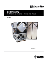
DIFFERENTIAL STATIC ACROSS CORE DSP VS. CFM
HE6X
DSP 0.20 0.30 0.40 0.50 0.60 0.70 0.80 0.90 1.0
Fresh Air
(FA) CFM 1720 2430 3060 3680 4220 4660 5110 5555 6000
Room Air
(RA) CFM 1600 2290 2860 3430 4000 4450 4890 5340 5780
The individual differential static pressures (DSP)
can be measured using the installed pressure ports
located in the front of the units core access doors.
NOTE: These ports have been carefully located on
the unit as to give you the most accurate airflow
measurement. Do not relocate pressure ports.
• To read SCFM of Fresh Air (FA) install the “high”
pressure side (+) of your measuring device to
the Outside Air (OA) port and the “low” pressure
side (-) to the Fresh Air (FA) port.
• To read SCFM of Room Air (RA) install the “high”
pressure side (+) of your measuring device to
the Room Air (RA) port and the “low” pressure
side (-) to the Exhaust Air (EA) port.
• Use the reading displayed on your measurement
device to cross reference the CFM output using
the conversion chart.
NOTE: Be sure to replace cap into pressure port
when air flow measuring is completed.
CROSS CORE STATIC PRESSURE MEASUREMENT INSTRUCTIONS
F4 PRESSURE PORT DIAGRAM HE6XIN
FA
Pressure Ports (4)

ERV HE6X
RENEWAIRE.COM INSTALLATION, OPERATION AND MAINTENANCE MANUAL 1.800.627.449918
FILTER SPECIFICATIONS
• (12) 20” x 20” x 2” (nominal) pleated filters. Actual size: 19.5” x 19.5” x 1.75”.
• Unit shipped with MERV-8 Filters. Minimum recommended effectiveness: MERV-6
Pleated_Filter_PD_OCT17 (6)20x20x2 MERV 8 (IOM)
0.0
0.1
0.2
0.3
0.4
1000 2000 3000 4000 5000 6000 7000
Clean-filter Pressure Drop (in.w.g.)
Unit Airflow (CFM)
Initial Pressure Drop of MERV 8 Filters
supplied with this unit
INITIAL PRESSURE DROP OF MERV 8 FILTERS SUPPLIED WITH THIS UNIT
Pleated_Filter_PD_OCT17 (6)20x20x2 MERV 13 (IOM)
0.0
0.1
0.2
0.3
0.4
1000 2000 3000 4000 5000 6000 7000
Clean-filter Pressure Drop (in.w.g.)
Unit Airflow (CFM)
Initial Pressure Drop of MERV 13 Filters
(available option)
INITIAL PRESSURE DROP OF MERV13 FILTERS AVAILABLE AS AN OPTION.
NOTE: pressure drop of standard filter supplied is included in unit airflow performance tables
MEASURING AIR FLOW
START-UP & OPERATION

ERVHE6X
19 1.800.627.4499 INSTALLATION, OPERATION AND MAINTENANCE MANUAL RENEWAIRE.COM
This page intentionally left blank.

ERV HE6X
RENEWAIRE.COM INSTALLATION, OPERATION AND MAINTENANCE MANUAL 1.800.627.449920
MAINTENANCE
SERVICE PARTS HE6XIN
/