Page is loading ...

Manual drawn up in accordance with EC
Directive 06/42
DropsA products can be purchased from DropsA branches and authorized distributors,
visit www.dropsa.com/contact or contact us at sales@dropsa.com
LUBRICATING PUMP AM
CB2235IE WK 47/22
User Operating and Maintenance Manual
Original Instructions

2
Contents
1. About the operating instructions ............................................................................................................ 3
1.1. Preface ........................................................................................................................................................................ 3
1.2. Information on documentation .................................................................................................................................. 3
1.3. Warranty .................................................................................................................................................................... 3
1.4. Designated use ........................................................................................................................................................... 3
1.5. General information on these instructions ................................................................................................................ 4
1.6. Copyright .................................................................................................................................................................... 4
2. Safety and precautionary measures for operation .................................................................................. 5
2.1. Safety instructions ...................................................................................................................................................... 5
2.2. Personnel qualification ............................................................................................................................................... 6
2.3. Duties of the owner .................................................................................................................................................... 6
2.4. Personal protective equipment .................................................................................................................................. 6
3. General technical description ................................................................................................................. 7
3.1. Function ...................................................................................................................................................................... 7
3.2. Technical data ............................................................................................................................................................ 7
3.3. Dimensions ................................................................................................................................................................. 9
3.4. Fluid diagram .............................................................................................................................................................. 9
4. Installation .......................................................................................................................................... 10
4.1. Installation of the lubricating pump ......................................................................................................................... 10
4.2. Installation of the lubricant lines .............................................................................................................................. 12
4.3. Electrical connections ............................................................................................................................................... 13
5. CE Declaration of Conformity ............................................................................................................... 14
6. UK Declaration of Conformity .............................................................................................................. 15
7. Maintenance ....................................................................................................................................... 16
7.1. Cleaning .................................................................................................................................................................... 16
7.2. Spare parts ............................................................................................................................................................... 16
7.3. Storage ..................................................................................................................................................................... 16
8. Decommissioning ................................................................................................................................ 16
8.1. Dismantling ............................................................................................................................................................... 17
8.2. Disposal .................................................................................................................................................................... 17
9. Scope of validity .................................................................................................................................. 17
10. Product monitoring .............................................................................................................................. 17
Copyright ......................................................................................................................................... 18

3
1. ABOUT THE OPERATING INSTRUCTIONS
1.1. PREFACE
These instructions are intended to make it easier for you to familiarise yourself with the machine and the ways in which it can
be used as intended.
The instructions contain important information on operating the machine safely, correctly and efficiently. Paying attention to
them will help you to avoid dangers, keep repair costs and downtimes to a minimum, and increase the machine's reliability
and service life.
These instructions are intended to familiarise the operator of the machine with
the following information:
• safety information,
• operation,
• operating procedures,
• servicing and maintenance.
This documentation serves to supplement instructions based on existing national legislation governing the prevention of
accidents and environmental protection.
1.2. INFORMATION ON DOCUMENTATION
These operating instructions must be read carefully before commissioning the lubricating pump. The corresponding lubricating
pumps may only be set up and operated in conjunction with these operating instructions. The lubricating pumps may only be
started up and operated by qualified personnel.
All descriptions and information in these instructions apply to the current state at the time it was created. We reserve the right
to change the contents of this document without notice. Furthermore, Dropsa BM Germany GmbH assumes no liability for
damages directly or indirectly attributable to delivery, performance and use of this material.
The textual and drawing representation may not necessarily comply with the scope of the main contract. The technical
drawings may not necessarily be represented to the specified scale.
1.3. WARRANTY
Dropsa BM Germany GmbH assumes no liability and guarantee for damage and malfunctions resulting from a failure to observe
these instructions or due to improper repairs carried out by the owner's personnel.
Unauthorised modifications to the machine and changes to the programs can pose a danger to personnel or damage the
machine.
1.4. DESIGNATED USE
The lubricating pump is a sturdy, simply constructed pneumatic pump. It is a complete machine and is used in the field of
lubrication. It is suitable for automated lubrication that needs to be performed several times a day up to a maximum of once
a minute.
Any other use or use beyond this definition is improper and represents misuse of the system. Dropsa BM Germany GmbH is
not liable for any damage resulting from this, and the warranty also becomes void.
Compliance with the documentation and proper performance of maintenance work are prerequisites for the designated use
of the system.

4
1.5. GENERAL INFORMATION ON THESE INSTRUCTIONS
These instructions are a guide for the use of the lubricating pump from Dropsa BM Germany GmbH. The basic system structure
and its individual components are described in general. The operating instructions also contain information on system-relevant
characteristics. Customer specific modifications in the general system structure must be coordinated separately with Dropsa
BM Germany GmbH and are not taken into account in these instructions.
1.6. COPYRIGHT
©2022 Dropsa BM Germany GmbH, D-72636 Frickenhausen.
This documentation is protected by copyright.
All rights reserved, including translation. All rights reserved for the case of granting of patent or registration of utility model.
No part of this documentation may be reproduced in any form whatsoever (e.g. print, copy, microfilm or other procedure), or
processed, duplicated or disseminated in data processing systems. Contraventions shall be liable for damages. Reprinting, even
in extract form, is only allowed with the permission of Dropsa BM Germany GmbH.
We reserve the right to carry out technical modifications to the machine at any time in order to improve its safety, reliability,
function and design.

5
2. SAFETY AND PRECAUTIONARY MEASURES FOR OPERATION
2.1. SAFETY INSTRUCTIONS
Please read this manual carefully before commissioning. The safety regulations of the country in which the device is installed
must be observed. It is necessary to use trained personnel for the various maintenance, use, installation, etc. operations
required during the service life of the device.
This manual uses safety markings and symbols in accordance with ANSI Z535, ISO 3864 and ISO 7010, which are listed below:
SAFETY INSTRUCTIONS TABLE
SIGNAL WORD
HAZARD
MEANING
EFFECT
Personal injury
Hazardous situation that is certain to
result in severe injury or death if not
avoided.
Death or severe injury,
debilitating.
Hazardous situation that could result in
severe injury or death if not avoided.
Possible death or severe
injury.
Hazardous situation that could result in
a minor to moderate injury if not
avoided.
Possible minor or
moderate injuries
Material
damage
Behaviour unrelated to personal injury.
Tips and other information.
Damage to objects, not to
persons.
DANGER
WARNING
CAUTION
NOTE

6
SYMBOL TABLE
DANGER
PROHIBITION
MANDATORY ACTION
General hazard warning
General prohibition
General mandatory sign
Danger! Laser!
No open flame; fire,
open source of
ignition and smoking
Follow instructions
Danger! Electric shock
hazard!
Carrying metal parts
or watches
prohibited
Wear ear protectors
Warning! Hot surface!
Touching prohibited
Use eye protection
Warning! Gas cylinders!
Extinguishing with
water prohibited
Ground before use
Warning! Danger of
crushing!
Pull out the mains plug
Warning! Potentially
explosive atmosphere!
Wear gloves
2.2. PERSONNEL QUALIFICATION
This documentation is intended for operating and setup personnel.
Operating personnel:
Have been trained to operate the lubricating pump. They can execute the machine operator functions and access the menus
required to operate the machine. Machine operators may only perform tasks for which they have received adequate training
and which they are fully able to perform.
Setup personnel:
Are specially trained and authorised for setup activities.
In addition, they are trained and instructed for activities within the scope of cleaning.
2.3. DUTIES OF THE OWNER
The owner must ensure that only authorised persons work with the machine.
2.4. PERSONAL PROTECTIVE EQUIPMENT
For certain work you need general protective equipment, which ensures your personal protection.
This must be provided by the owner of the machine.

7
3. GENERAL TECHNICAL DESCRIPTION
3.1. FUNCTION
When compressed air is applied to the piston chamber of the pneumatic piston, the piston assembly pushes the lubricant
through the non-return valve into the lubrication line.
After the stroke, the lubrication line must be depressurised again so that the valves can return to their starting position and be
prepared for the next stroke. The lubrication line is depressurised via the relief valve in the single piston pump.
If, for any reason, the pump is pressurised with excessively high pneumatic pressure, this could lead to component failure. To
counteract this danger, the pump is equipped with a pressure relief valve. If the pressure in the system rises too high, the
lubricant in the pump flows back into the tank via a bypass.
If the level in the tank reaches a defined minimum, this is detected by a level control, which signals a warning.
The fluid can be filled manually via the filler cap or via a filling nipple.
3.2. TECHNICAL DATA
General information
Type
Single piston pump
Lubrication line connection
Pipe connection Ø 6 mm
Ambient temperature
0°C to 80°C
Filling
Manual
Installation position
Vertical
IP rating as per EN60529
IP 67
Weight
4.1 kg (1.2 l tank)
4.3 kg (3.0 l tank)
Use
Single-line lubrication systems
Hydraulics
Operating pressure
PFluid =10.0 x (PAir – 0.6)
Pressure limitation
60 bar
Supply volume
25 cm³/stroke
Operating medium
Low-viscosity grease, mineral oil
Viscosity range
NLGI 000-0 (according to approval list for low-
viscosity grease)
50-750 mm2/s
Drive
Type of drive
Pneumatic
Supply pressure
4 to 6 bar
Supply connection
G ¼
CAUTION
The single piston pump generates a sound pressure level of approx. 65 dB(A).

8
NOTE
Specification of the weight on the transport packaging.
The pump weighs approx. 4.3 kg.
DANGER
Adjustment of various pressures on the pump is prohibited and constitutes misuse of the
system.
DANGER
Handling lubricants can cause damage to health. The safety data sheet of the lubricant
manufacturer must be observed.
Only suitable lubricants may be used. Unsuitable lubricants can lead to lubrication failure and
thus to severe damage to the machine.
Foreseeable misuse is use of highly flammable, combustible fluids.
The permissible lubricating fluids are specified – the flash point of the lubricating fluids must
be above 150°C.

9
3.3. DIMENSIONS
Exemplary representations
3.4. FLUID DIAGRAM

10
4. INSTALLATION
4.1. INSTALLATION OF THE LUBRICATING PUMP
NOTE
When handling hydraulic systems, attention should be paid to the standard of cleanliness typically observed in
hydraulics!
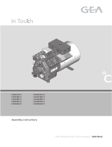
Figure 1 – Installation (exemplary representation)
Pos.
Assembly
Pos.
Assembly
1
Tank, large
5
Compressed air connection
2
Level control connection
6
Tank, small
3
Lubrication line connection
7
Level control, capacitive
4
Mounting holes
8
Filler cap
1
2
6
8
5
5
7
3
7
4

11
Place the pump in its designated location and fasten it in position using the mounting holes.
Connect all hoses through which the lubricant reaches the lubrication point, the pump drive and the level control.
Once all hoses and cables have been attached, unscrew the cap of the pump and fill the tank with lubricant. Make sure that
the tank is not overfilled.
The pump should be vented carefully by performing strokes. Vent the pump until the pump no longer expels air.
The lubricating pump must be mounted vertically (± 5°) to the lubricant tank axis (see Figure 2: Installation dosing pump). It is
attached via two through holes in the housing. Make sure that there is sufficient space above and to the side of the
lubricating pump to fit the electrical connectors and fluid connections.
WARNING
Personal protective equipment – Wear protective goggles/face protection, protective gloves,
ear protectors, safety helmet and safety shoes. Remove tight-fitting clothing, any jewellery
such as rings, wristwatches, neck jewellery, etc.
WARNING
Route or lay hoses/cables so that they do not become a trip hazard.
Attach to the machine frame etc. if necessary.
WARNING
Leakage of lubrication fluid must be removed immediately.
DANGER
When working at a fall height of more than 0.5 m, use the appropriate climbing aids and
working platforms.
CAUTION
Minimum space or room required for movement: radius of approx. 1.5 m around the machine.

12
NOTE
Carry out the work on the single piston pump as ergonomically as possible. For example, the pump should be fastened
at an ergonomically easily accessible height.
4.2. INSTALLATION OF THE LUBRICANT LINES
Insert the lubricant lines into the screw fitting and tighten the union nut by hand. Align the lubricant line so that it is not strained
and tighten the union nut with 1.5 turns.
NOTE
The main lines must be vented during commissioning. If necessary, vent the pump without the main line. It is
recommended to connect the lubrication lines to the lubrication point pre-filled.

13
4.3. ELECTRICAL CONNECTIONS
Level control sensors
Capacitive level control
Nominal voltage
24 V DC
Switching
current
≤ 100 mA
Current
consumption
(idle)
≤ 17 mA
Connection
M8x1
Float switch
Nominal voltage
24 V DC
Switching
current
≤ 100 mA
Connection
M12x1
DANGER
• The electrical voltage must match the specification on the rating plate.
• Only use approved fuses with the prescribed amperage.
• Immediately replace damaged electrical wiring using a qualified electrician!
• Follow the five golden rules of electrical safety.

14
5. CE DECLARATION OF CONFORMITY

15
6. UK DECLARATION OF CONFORMITY

16
7. MAINTENANCE
Regular and proper service is required to maintain operability of the lubrication system. Maintenance work may only be carried
out by appropriately qualified personnel. Safety, reliability and service life of the lubrication system significantly depend upon
proper execution. Damage attributable to improper maintenance and servicing shall be borne by the party causing the damage.
Maintenance work on the pumps may only be carried out by Dropsa BM Germany.
The customer is not permitted to carry out maintenance or other repairs itself. Dropsa BM Germany accepts no liability or
warranty for this.
WARNING
Enclosed hydraulic pressure in the pump. Vent the pump before starting maintenance and
repair work.
WARNING
All screw connections must be checked regularly for tightness. If necessary, retighten the
screw connections.
7.1. CLEANING
Regular servicing and cleaning are essential for reliable and safe operation. The maintenance intervals depend on the operating
and ambient conditions and on the daily operating time. The lubrication system must be cleaned regularly from the outside,
depending upon the degree of fouling.
7.2. SPARE PARTS
Genuine spare parts for the lubrication system can be obtained from Dropsa BM Germany.
7.3. STORAGE
When storing the lubrication system, always close all open connections. Store in a clean and dry location.
8. DECOMMISSIONING
The personnel charged with dismantling and disposal must be sufficiently qualified and authorised for this activity. They must
be familiar with the relevant national and regional regulations concerning waste disposal.

17
8.1. DISMANTLING
Depending on the version and the installed components of the lubrication system, all operating materials, such as oils and
fluids, must be drained as far as possible. The individual components are to be dismounted with the help of the assembly
instructions.
WARNING
Danger! Electric shock hazard!
Risk of danger to life! Disconnect the lubrication system from all electrical interfaces before
any service and maintenance activities, and check whether they are de-energised.
DANGER
Hydraulic overpressure! Serious injuries! Before any service and maintenance activities,
switch off the lubrication system’s hydraulic pressure generator and check that it is free of
pressure.
8.2. DISPOSAL
Pay attention to environmental compatibility, health risks, waste disposal regulations and the local possibilities for disposal in
accordance with applicable legislation. Detailed information can be obtained from the appropriate authority. All operating
materials, in particular oil, greases, lubricants and condensates must be disposed of in accordance with the applicable national
and regional regulations.
NOTE
You may find oil, grease, lubricants, condensates or similar substances in all tanks, pipelines and valves of the lubrication
system.
NOTE
All tanks, lines and valves must be drained so there are no residual quantities of liquids requiring disposal!
NOTE
You are responsible for compliance with the applicable environmental protection laws and regulations; if required, the
components, including electronic components, must be disposed of in an environmentally responsible manner by
specialists!
9. SCOPE OF VALIDITY
P30011626 to P30011662
10. PRODUCT MONITORING
Dropsa BM Germany is very interested in monitoring its products even after delivery. Please share with us your experiences
with the products.
Dropsa BM Germany
Siemensstraße 11
72636 Frickenhausen
+49 (0) 7022 24933-440

18
DropsA SpA
Via Benedetto Croce,1
20055 Vimodrone (MI)
Tel: +39 02 250 79 1
Fax: +39 02 250 79 767
www.dropsa.com
Copyright
© 2022 DropsA SpA Via Benedetto Croce, 1- 20055 Vimodrone (MI)
This document is protected by copyright.
All rights reserved, including translation.
All rights reserved in the event of granting of patents or registration of a utility model.
No part of this document may be reproduced in any form (e.g. printed material, copying, microfilm or any other method) or processed,
duplicated or distributed in data processing systems.
Fines will be applied for damages. Reprints, including extracts, are allowed only with the approval of DropsA SpA.
We reserve the right to make technical changes to the equipment at any time to improve safety, reliability, functionality and design.
All descriptions and information contained in this product catalogue apply to the state at the time of creation.
We reserve the right to change the contents of this document without notice.
The software and hardware names used in this document and the trade names of individual companies are subject to general protection
under trademark or patent laws.
The text and drawings contained in this manual may not necessarily conform to the supply.
Technical drawings may not necessarily be drawn to scale.
/