Page is loading ...

1-EN
LCD WALL MOUNT
For Model:
SHO 1020
SHO 1021
Universal Mounting Instructions

2-EN
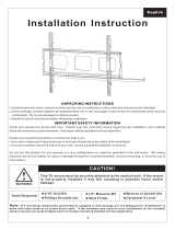
Installation Instruction
UNPACKING INSTRUCTIONS
• Carefully open the carton, remove contents and lay out on cardboard or other
protective surface to avoid damage.
• Check package contents against the Supplied Parts List in the next page to assure that
all components were received undamaged. Do not use damaged or defective parts.
• Carefully read all instructions before attempting installation.
IMPORTANT SAFETY INFORMATION
Install and operate this device with care. Please read this instruction before beginning
the installation, and carefully follow all instructions contained herein. Use proper safety
equipment during installation.
Please call a qualifi ed installation contractor for help if you:
• If you don‘t understand these directions or have any doubts about the safety of the
installation.
• If you are uncertain about the nature of your wall, consult a qualifi ed installation
contractor.
Do not use this product for any purpose or in any confi guration not explicitly specifi ed in
this instruction. We hereby disclaims any and all liability for injury or damage arising from
incorrect assembly, incorrect mounting, or incorrect use of this product.
Note: Specifi cations and the design are subject to possible modifi cation without notice due
to improvement.

3-EN
IMPORTANT:
• Before installation and use, carefully read this guide and keep it for future use.
• When using electrical tools for tightening bolts, please pay increased attention.
• When tightening bolts make sure not to strip the thread. It could damage the video
table / holder. Don‘t install this product into a wet or otherwise damaged wall. Fastening
materials, which are supplied with the product are designed for installation on to walls
from massive wood, bricks or concrete. For assembly on to walls from other materials
consult an expert.
• Do not disassemble nor repair the product on your own.
• Never install or service this product if it shows signs of damage. If you are unsure,
contact your supplier. Stell takes no responsibility for the faulty installation of this
product.
• The product must be placed in such a way that the power socket is accessible after
installation.
• Sharp edges of this product may cause injury.
• This product is not designed to be handled nor installed by small children or
uninstructed persons, unless they are under the supervision of persons responsible for
ensuring safety during handling or installation of the product. Children should be under
supervision to ensure that they do not tamper with the product. Do not allow children
to hang on the product nor to handle it in any other way. If this is not the case, serious
injury may occur. Never insert fi ngers nor other items into the product‘s mechanism.
Persons could be injured or property damaged.
• Use this product in accordance with the user‘s manual and its intended application.

4-EN
Supplied Parts List
(1) Wall Plate-a (1) Left Mornitor Bracket-b (1) Right Monitor Bracket-c
(4) M4x12 Bolt-d (4) M5x12 Bolt-e (4) M6x12 Bolt-f (4) M8x16 Bolt-g
(4) M4x30 Bolt-h (4) M5x30 Bolt-i (4) M6x35 Bolt-j (4) M8x40 Bolt-k
(4) M4 Lock Washer-l (4) M5 Lock Washer-m (4) M6 Lock Washer-n (4) M8 Lock Washer-o
(4) M4/M5 Space-p (4) M6/M8 Space-q (8) M4/M5 Washer-r (4) M6/M8 Washer-s
(4) Lag Bolt-t (4) Lag Bolt Washer-u (4) Concrete Anchor-v

5-EN
WARNING
CAUTION!
This TV mount must be securely attached to the wall. If the mount
is not properly installed it may fall, resulting in possible injury and/or
damage.
Tools
Required
3/16“ Drill Bit
Screwdriver
½“ Masonry Bit
Stud Finder
Wrench or Socket Set
Carpenter‘s Level
Note: The mounting components and hardware supplied in this package are not
designed for installations to ceilings with steel studs. If the hardware you need for
your installation is not included, please consult your local hardware store for proper
mounting hardware for the application.
Step 1A Mounting the Monitor Brackets to a TV with Flat Back
First of all, make sure the diameter of the Bolt (d, e, f, g) your TV requires. Once you have
determined the correct diameter, please see the relative diagram as below. You will thread
the Bolt into the TV using the correct Lock Washer (l, m, n, o) and Washer (r, s). Please
make sure the Monitor Brackets (b, c) are vertically centered and levelled with each other.
M4 Diameter Bolt M6 Diameter Bolt
Diagram 1A
M5 Diameter Bolt M8 Diameter Bolt

6-EN
Step 1B Mounting the Monitor Brackets to a TV with Curved Back
First of all, make sure the diameter of the Bolt (h, i, j, k) your TV requires. Once you have
determined the correct diameter, please see the relative diagram as below. You will thread
the Bolt into the TV using the correct Lock Washer (l, m, n, o), Washer (r, s) and spacer
(p, q). For the M4 or M5 diameter bolt, you will need another M4/M5 Washer between the
Monitor Bracket and the Spacer. Please make sure the Monitor Brackets are vertically
centered and level with each other.
Step 2 Mounting the Wall Plate to the Wall
Brick, Solid Concrete and Concrete Block mounting:
Use the Wall Plate (a) as a template to mark 4 hole locations on the wall. Make sure these
holes are level. Pre-Drill these holes with a 1/2” masonry bit to at least 2.5” in depth. Insert
a Concrete Anchor (v) into each of these holes. Make sure the anchor is seated completely
fl ush with the concrete surface even if there is a layer of drywall or other material in front.
Attach the Wall Plate to the wall using 4pcs Lag Bolts (t) and 4pcs Lag Bolt Washers (u),
shown in Diagram 2A.
M4 Diameter Bolt M6 Diameter Bolt
Diagram 1B
M5 Diameter Bolt M8 Diameter Bolt

7-EN
Wood Stud mounting:
The Wall Plate (a) must be mounted to two wood studs at least 16” apart. Use a stud
fi nder to locate two adjacent studs. It is a good idea to verify where the studs are located
with an awl or thin nail shown in Diagram 2B. Pre-drill a 2.5” deep hole at the desired
height in each stud using a 3/16” drill bit. Make sure these holes are in the center area of
the studs and level with each other. Attach the Wall Plate to the wall using the 2pcs Lag
Bolts (t) and 2pcs Lag Bolt Washers (u).
Diagram 2A Diagram 2B
Stud Finder
16 inch
16 inch
16 inch
Step 3 Attaching Monitor to Wall Plate
Warning: Some TVs may require two people to lift! We are not responsible for
personal injury or product damage.
First hook the Monitor Brackets (b, c) over the top of the wall Plate (a), then let the bottom
of the Monitor Brackets rotated to the wall as shown in the Diagram 3A. Finally push the
each metal piece on the arms up and fasten the screws by screw driver, the fi nishing
looking as shown in the Diagram 3B.
Diagram 3A Diagram 3B
wall
wall
Lock
system
Thanks for choosing our products, enjoy the using!
/