Page is loading ...

INSTALLATION INSTRUCTIONS
FRONT CONTROL 30" GAS RANGE
Printed in United States
Table of Contents
Important Notes to the installer ...................................... 1
Important Note to the Customer .................................... 1
Clearances and Dimensions ........................................... 2
Important Safety Instructions .......................................... 3
Tools You Will Need ........................................................ 4
Normal Installation Steps:
1. Anti-Tip Bracket Installation Instructions Important
Safety Warning ......................................................4-5
2. Provide an Adequate Gas Supply ............................ 6
3. Seal the Openings ................................................... 6
4. Connect the Range to the Gas Supply .................... 7
5. Electrical Requirements ........................................... 8
6. Assembly of the Burner Caps .................................. 8
7. Electric Ignition Surface Burner ............................... 9
8. Adjust the Low Setting of Surface Burner Valves ..... 9
9. Operation of Oven Burners and Oven Adjustment ... 9
10. Air Shutter-Broil Burner .......................................... 10
11. Make Sure Range is Level ..................................... 10
12. After Installation is Complete Make sure all Controls
are Left in the OFF Position ................................... 10
LP/Propane Gas Conversion ........................................ 10
Care, Cleaning and Maintenance ................................. 10
Before You Call for Service ........................................... 10
Serial Plate Location .................................................... 10
Important Notes to the Installer
1. Read all instructions contained in these installation
instructions before installing range.
2. Remove all packing material from the oven and
the drawer compartments before connecting the
electrical and gas supply to the range.
3. Observe all governing codes and ordinances.
4. Be sure to leave these instructions with the consumer.
5. Note: For operation at 2000 ft. elevations above sea
level, appliance rating shall be reduced by 4 percent
for each additional 1000 ft.
Important Note to the Consumer
Keep these instructions with your owner's guide for
future reference.
INSTALLATION AND SERVICE MUST BE PERFORMED BY A QUALIFIED INSTALLER.
IMPORTANT: SAVE FOR LOCAL ELECTRICAL INSPECTOR'S USE.
READ AND SAVE THESE INSTRUCTIONS FOR FUTURE REFERENCE.
FOR YOUR SAFETY: Do not store or
use gasoline or other fl ammable vapors and liquids
in the vicinity of this or any other appliance.
If the information in this manual is not followed
exactly, a fi re or explosion may result causing property
damage, personal injury or death.
FOR YOUR SAFETY:
— Do not store or use gasoline or other fl ammable
vapors and liquids in the vicinity of this or any other
appliance.
— WHAT TO DO IF YOU SMELL GAS:
• Do not try to light any appliance.
• Do not touch any electrical switch; do not use any
phone in your building.
• Immediately call your gas supplier from a neighbor's
phone. Follow the gas supplier's instructions.
• If you cannot reach your gas supplier, call the fi re
department.
— Installation and service must be performed by a
qualifi ed installer, service agency or the gas supplier.
Note: For appliance installed in the State of
Massachusetts see page 2.
Tip Over Hazard
• A child or adult can tip the range and
be killed.
• Verify the anti-tip device has been
installed to fl oor or wall.
• Ensure the anti-tip device is re-
engaged to fl oor or wall when the range is moved.
• Do not operate the range without the anti-tip device
in place and engaged.
• Failure to follow these instructions can result in
death or serious burns to children and adults.
Range
leveling
leg
Anti-tip
bracket
To check if the anti-tip bracket is installed
properly, use both arms to grasp the rear
edge of the range back. Carefully attempt to
tilt range forward. When properly installed,
the range should not tilt forward.
Refer to the anti-tip bracket
installation instructions supplied
with your range for proper
installation.
P/N 809127201 (1405) Rev. A
English – pages 1-10
Spanish - pages 11-20
Français - pages 21-30

2
30" GAS RANGE INSTALLATION INSTRUCTIONS
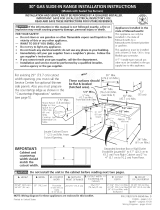
Clearances and Dimensions
1. Location—Check location where the range will be installed. Check for proper electrical and gas supply, and the
stability of fl oor.
2. Dimensions that are shown must be used. Given dimensions provide minimum clearance. Contact surface
must be solid and level.
* 30" minimum clearance between the top of the cooking
surface and the bottom of an unprotected wood or
metal cabinet; or 24" minimum when bottom of wood
or metal cabinet is protected by not less than ¼" fl ame
retardant millboard covered with not less than no.
28 MSG sheet steel, 0.015" stainless steel, 0.024"
aluminum or 0.020" copper. The minimum clearance
is 0" for the rear of the range. Follow all dimension
requirements provided above to prevent property
damage, potential fi re hazard, and incorrect countertop
and cabinet cuts.
Avoid locating cabinet storage space above the
surface burners to eliminate the possibility of cabinets
catching on fi re, or personal burns from reaching for
the cabinets over the heated units. Avoid locating
cabinet storage space above the surface burners.
The absence of cabinets will eliminate the chance of
cabinets catching on fi re, and eliminate the possibility
of receiving personal burns from reaching for the
cabinets over flaming surface burners. If cabinet
storage is to be provided, risk can be reduced by
installing a range hood that projects horizontally a
minimum of 5" beyond the bottom of the cabinets.
DO NOT MAKE ANY ATTEMPT
TO OPERATE THE ELECTRIC IGNITION OVEN
DURING AN ELECTRICAL POWER FAILURE.
RESET ALL OVEN CONTROLS TO OFF IN THE
EVENT OF A POWER FAILURE. The electric ignitor
will automatically re-ignite the oven burner when
power resumes if the oven thermostat control was
left in the ON position.
When an electrical power failure occurs during use,
the surface burners will continue to operate.
During a power outage, the surface burners can be
lit with a match. Hold a lighted match to the burner,
then slowly turn the knob to the Lite position. Use
extreme caution when lighting burners this way.
Special instructions for appliances installed in the state
of Massachusetts:
This Appliance can only be installed
in the state of Massachusetts by a Massachusetts
licensed plumber or gas fi tter. When using a fl exible
connector, it must not exceed three (3) feet (36 in.) long.
A "T" handle type manual gas valve must be installed in
the gas supply line to this appliance.
7”
30” Minimum*
30”
Minimum to
wall on either
side of range
above 36” height.
36”
18”
Minimum to
cabinets on
either side
of range
30 1/8”
25” Max.
13”
Maximum depth
for cabinets
above range top.
0” clearance below cooking top and at rear of range
Typical cabinet installationFront
view
Side
view
Front View
Maximum
Door open
29
7
/
8
"
46"
26"
36
3
/
8
"
±
1
/
4
"

3
30" GAS RANGE INSTALLATION INSTRUCTIONS
IMPORTANT SAFETY
INSTRUCTIONS
Installation of this range must conform with local codes or,
in the absence of local codes, with the National Fuel Gas
Code ANSI Z223.1/NFPA .54-latest edition or CAN/CGA-
B149.1 and CAN/CGA-B149.2 standards.
When installed in a manufactured (mobile) home,
installation must conform with the Manufactured Home
Construction and Safety Standard, Title 24 CFRR, Part
3280 [formerly the Federal Standard for Mobile Home
Construction and Safety, Title 24, HUD (Part 280)] or,
when such standard is not applicable, the Standard
for Manufactured Home Installations, ANSI/NCSBCS
A.225.1, or with local codes in United States or with
ANSI Z225.1/NFPA 501A-latest edition, or CAN/CSA-
Z240MH in Canada.
This range has been design certifi ed by CSA
International. As with any appliance using gas and
generating heat, there are certain safety precautions
you should follow. You will fi nd them in the Use and
Care Guide, read it carefully.
• Be sure your range is installed and grounded
properly by a qualifi ed installer or service
technician.
• This range must be electrically grounded in
accordance with local codes or, in their absence,
with the National Electrical Code ANSI/NFPA No.
70—latest edition in United Sates or with CSA
standard C22.1, Canadian Electrical Code, Part 1 in
Canada. See Grounding Instructions in the Electrical
Requirements section of these Installation Instructions.
• Before installing the range in an area covered with
linoleum or any other synthetic fl oor covering, make
sure the fl oor covering can withstand heat at least 90°F
above room temperature without shrinking, warping or
discoloring. Do not install the range over carpeting unless
you place an insulating pad or sheet of ¼" (10,16cm)
thick plywood between the range and carpeting.
• Make sure the wall coverings around the range can
withstand the heat generated by the range.
• Do not obstruct the fl ow of combustion air at the oven
vent nor around the base or beneath the lower front
panel of the range. Avoid touching the vent openings or
nearby surfaces as they may become hot while the oven
is in operation. This range requires fresh air for proper
burner combustion.
• Air curtains or other overhead range hoods, which
operate by blowing a downward air fl ow onto a range,
shall not be used in conjunction with gas ranges other
than when the hood and range have been designed,
tested and listed by an independent test laboratory for
use in combination with each other.
Never leave children alone or unattended
in the area where an appliance is in use. As children grow,
teach them the proper, safe use of all appliances. Never
leave the oven door open when the range is unattended.
Stepping, leaning or sitting on the doors
or drawers of this range can result in serious injuries and
can also cause damage to the range.
• Do not store items of interest to children in the cabinets
above the range. Children could be seriously burned
climbing on the range to reach items.
• To eliminate the need to reach over the surface burners,
cabinet storage space above the burners should be
avoided.
• Adjust surface burner fl ame size so it does not extend
beyond the edge of the cooking utensil. Excessive fl ame
is hazardous.
• Do not use the oven as a storage space. This creates a
potentially hazardous situation.
• Never use your range for warming or heating the room.
Prolonged use of the range without adequate ventilation
can be dangerous.
• Do not store or use gasoline or other fl ammable vapors
and liquids near this or any other appliance. Explosions
or fi res could result.
• In the event of an electrical power outage, the surface
burners can be lit manually. To light a surface burner,
hold a lit match to the burner head and slowly turn the
Surface Control knob to LITE. Use caution when lighting
surface burners manually.
• Reset all controls to the "off" position after using a
programmable timing operation.
• Remove broiler pan, food and other utensils before self-
cleaning the oven. Wipe up excess spillage. Follow the
precleaning instructions in the Use and Care Guide.
• Unlike the standard gas range, THIS COOKTOP IS NOT
REMOVABLE. Do not attempt to remove the cooktop.

4
30" GAS RANGE INSTALLATION INSTRUCTIONS
Tools you will need
For leveling legs and anti-tip brackets:
● Adjustable wrench or channel
lock pliers
●
5/16" Nutdriver or Flat Head
Screw Driver
● Electric Drill & 1/8 Diameter
Drill Bit (5/32" Masonry Drill
Bit if installing in concrete)
● Level & Measuring Tape
For gas supply connection:
● Pipe Wrench
● Brush
For burner fl ame adjustment
● Phillips head and blade-type
screwdrivers
For gas conversion (LP/Propane or Natural):
● Open end wrench - 1/2"
Additional materials you will need
● Gas line shut-off valve
● Pipe joint sealant that resists action of LP/ Propane
gas
A. Locate the Bracket Using the Template -
Locate the bracket position (right or left side) by placing
the template symmetrically to the center of the fi nal
range position. Mark the location of the screw holes,
shown on template.
Figure 1
● A new fl exible metal appliance conduit
(½" NPT x ¾" or ½" I.D.) must be design
certifi ed by CSA International. Because
solid pipe restricts moving the range we
recommend using a new fl exible conduit
(4 feet length) for each new installation
and additional reinstallations.
● Always use the (2) new fl are union
adapters ½" NPT x ¾" or ½" I.D.) supplied
with the new fl exible appliance conduit for
connection of the range.
Normal Installation Steps
1
Anti-tip Bracket Installation Instructions
Important Safety Warning
To reduce the risk of tipping of the range, the range must be
secured to the fl oor by the properly installed anti-tip bracket
and screws packed with the range. Failure to install the anti-
tip bracket will allow the range to tip over if excessive weight
is placed on an open door or if child climbs upon it. Serious
injury might result from spilled hot liquids or from the range
itself.
If range is ever moved to a different location, the anti-tip
brackets must also be moved and installed with the range.
Instructions are provided for installation in wood or
cement fl oor. When fastening to fl oor, be sure that
screws do not penetrate electrical wiring or plumbing.
• A child or adult can tip the range and
be killed.
• Verify the anti-tip device has been
installed to fl oor or wall as per
installation instructions.
Tip Over Hazard
• Ensure the anti-tip device is re-engaged to fl oor or
wall when the range is moved.
• Do not operate the range without the anti-tip device
in place and engaged.
• Failure to follow these instructions can result in
death or serious burns to children and adults.
To check if the anti-tip bracket is installed properly,
use both arms and grasp the rear edge of range back.
Carefully attempt to tilt range forward. When properly
installed, the range should not tilt forward.
Range
Leveling
Leg
Anti-Tip
Bracket

5
30" GAS RANGE INSTALLATION INSTRUCTIONS
B. Drill Pilot Holes and Fasten Bracket - Drill
a 1/8" pilot hole where screws are to be located. If
bracket is to be mounted to the wall, drill pilot hole at
an approximate 20° downward angle. If bracket is to be
mounted to masonry or ceramic fl oors, drill a 3/16" pilot
hole 1-3/4" deep. The screws provided may be used in
wood or concrete material. Use a 5/16" nut-driver or fl at
head screwdriver to secure the bracket in place.
Figure 2
C. Level and position the range -
Slide range to
its fi nal position. Insert the range leveling leg in the anti-tip
bracket. Visually verify if the anti-tip bracket is engaged.
Lower the range by adjusting the 4 leveling legs alternatively
until the range is level. Check if the range is level by placing
a spirit level on the oven rack. Take 2 readings with the spirit
level placed diagonally; take a reading in one direction and
then in the other direction. Level the range if necessary by
adjusting the leveling legs.
Figure 3
Figure 4
Figure 5
Leg
Leveler
Raise
Lower

6
30" GAS RANGE INSTALLATION INSTRUCTIONS
2.2
Provide an adequate Gas Supply
When shipped from the factory, this unit is designed
to operate on 4" (10,16 cm) water column (1,0 kPa)
Natural gas manifold pressure. A convertible pressure
regulator is connected to the range manifold and
MUST be connected in series with the gas supply line.
If LP/Propane conversion kit has been used, follow
instructions provided with the kit for converting the
pressure regulator to LP/Propane use.
Care must be taken during installation of range not to
obstruct the fl ow of combustion and ventilation air.
For proper operation, the maximum inlet pressure to
the regulator should be no more than 14" (35,56 cm)
of water column pressure (3,5 kPa). The inlet pressure
to the regulator must be at least 1" (0,25 kPa) greater
than the regulator manifold pressure setting. Examples:
If regulator is set for natural gas 4" (10,16 cm) manifold
pressure, inlet pressure must be at least 5" (12,60 cm);
if regulator has been converted for LP/Propane gas 10"
(25,4 cm) manifold pressure, inlet pressure must be at
least 11" (27,9 cm).
Leak testing of the appliance shall be conducted
according to the instructions in step 4H.
The gas supply line should be ½" or ¾" I.D.
3
Seal the openings
Seal any openings in the fl oor under the range after
gas supply line is installed.
2.1
Gas and Electric Entry Preparation
• The hatched areas are the locations where the gas
line can enter the cabinet (fi gure 5a).
• The recommended position for the gas entry line is
located at 7" (17,8 cm) from the left cabinet wall and
2" (5,1 cm) from the fl oor (fi gure 5a).
• The shaded area is the location where the electric
outlet can be located (fi gure 5a).
• If you are using a through the fl oor gas entry,
remove the line protector shield from the bottom of
the unit to allow access for the pipe line (fi gure 5b).
• We recommend to install a pipe elbow right out of
the fl oor or wall towards the center of the unit to
ease the installation.
5
3
4
5
4.5
11
3
6
7½
2½
WALL
WALL
2½
2
2
30
(76.2)
(5.1)
(5.1)
12
(30.5)
Recommended
position
Note: All dimensions are in inches (centimeter).
Figure 5a
To remove the line protector, remove the 3 screws.
Figure 5b
Gas pressure regulator location

7
30" GAS RANGE INSTALLATION INSTRUCTIONS
Figure 5b
Figure 5c
4
Connect the range to the gas supply
Important: Remove all packing material and literature
from range before connecting gas and electrical supply.
Note: To prevent leaks, put pipe joint sealant on all
external pipe threads.
Do not allow regulator to rotate on
pipe when tightening fi ttings.
Connection to Pressure Regulator
The regulator is already installed on the appliance.
Do not make the connection too tight.
The regulator is die cast. Overtightening may crack the
regulator resulting in a gas leak and possible fi re or
explosion.
Checking Manifold Gas Pressure
Disconnect this range and its individual manual shutoff
valve from the gas supply piping system during any
pressure testing of that system at test pressures greater
than 14" water column pressure (approximately ½" psig).
The appliance must be isolated from the gas supply
piping system by closing its individual manual shutoff
valve during any pressure testing of the gas supply
piping system at test pressures equal to or less than
14" water column pressure (approximately ½" psig).
If it should be necessary to check the manifold gas
pressure, connect manometer (water gauge) or
other pressure device to the top burner right rear
orifi ce. Using a rubber hose with inside diameter of
approximately ¼" hold tubing down tight over orifi ce.
Turn burner valve on.
For accurate pressure check have at least two (2)
other top burners burning. Be sure the gas supply
(inlet) pressure is at least one inch above specifi ed
range manifold pressure. The gas supply pressure
should never be over 14" water column. When properly
adjusted for Natural Gas manifold pressure is 4" (For
LP/Propane Gas the manifold pressure is 10")
Note: The purpose of forming the gas fl exible
connector is to position it in a way that will not block
the unit or get pinched in it's fi nal position.
If your unit in place is not against the wall as you
wish, check behind the range and place the gas
fl exible connector to avoid the range being blocked
or the gas fl exible connector being pinched.
A. Install an external manual gas shut-off valve to gas
supply line in an accessible location outside of the
range. Be sure you know where and how to shut off
the gas supply to the range.
B. Install ½" fl are union adapter to unit shut-off valve
using NO MORE THAN 15ft./lbs. of torque.
NOTE: Be sure to stabilize the right side of the
unit shut-off valve with adjustable wrench before
tightening ANY fi ttings to the unit shut-off valve.
C. Tighten the gas fl exible connector and/or appliance
conduit to fl are union on the left side of the unit
shut-off valve using NO MORE THAN 15ft./
lbs. of torque. Be sure to stabilize the ½" fl are
union adapter with an adjustable wrench before
tightening the gas fl exible connector and/or
appliance conduit.
D. Install fl are union adapter to external shut-off valve.
E. Attach the gas fl exible connector with the fl are
union on shut-off valve.
F. Make sure both shut-off valves are in the "ON"
position.
G. Form the gas fl exible connector as shown on fi gure
5c. This will prevent the fl exible connector from
pinching or blocking the unit when you will push it
back in its fi nal position.
H. Check for leaks. Turn the gas supply on to the range
and use a liquid leak detector (or soap and water) at
all joints and conduits to check for leaks in the system.
Do not use a fl ame to check for gas
leaks.

8
30" GAS RANGE INSTALLATION INSTRUCTIONS
5
Electrical Requirements
120 volt, 60 Hertz, properly grounded dedicated circuit
protected by a 15 amp circuit breaker or time delay fuse.
Note: Not recommended to be installed with a Ground
Fault Interrupt (GFI).
Do not use an extension cord with this range.
Grounding Instructions
IMPORTANT Please read carefully.
For personal safety, this appliance must be
properly grounded.
The power cord of this appliance is equipped with a
3-prong (grounding) plug which mates with a standard
3-prong grounding wall receptacle (see Figure 6) to
minimize the possibility of electric shock hazard from the
appliance.
The wall receptacle and circuit should be checked by
a qualifi ed electrician to make sure the receptacle is
properly grounded.
6
Assembly of the Burner Caps
Refer to the Use and Care Guide packaged with the
cooktop for operating instructions and for care and
cleaning of your cooktop.
Do not touch the burners. They may
be hot enough to cause burns.
Install Burner Caps
This cooktop is equipped with sealed burners. All pieces
are at their place. Take note where they are. Remove all
packaging material. Make sure the burner caps are
properly aligned and leveled. The burner cap lip (See
Figure 7) should fi t snug into the center of burner head
and rest level. Refer to Figures 8 & 9 for correct and
incorrect burner cap placement. Once in place, you may
check the fi t by gently sliding the burner cap from side
to side (Figure 10) to be sure it is centered and fi rmly
seated. When the burner cap lip makes contact inside
the center of the burner head you will be able to feel
it. Please note that the burner cap should NOT move
off the center of the burner head when sliding from
side to side. NOTE: There are no burner adjustments
necessary on this cooktop.
Preferred Method
Grounding type
wall receptacle
Do not, under any
circumstances,
cut, remove,
or bypass the
grounding prong.
Power supply
cord with 3-prong
grounding plug.
Figure 6
Where a standard 2-prong wall receptacle is installed,
it is the personal responsibility and obligation of the
consumer to have it replaced by a properly grounded
3-prong wall receptacle.
Do not, under any circumstances, cut or remove
the third (ground) prong from the power cord.
Disconnect electrical supply cord from
wall receptacle before servicing cooktop.
Correct Burner
Cap Placement -
Fig. 8
Incorrect Burner
Cap Placement -
Fig. 9
Fig. 10
Burner Cap
Burner
Head
Fig. 7
Burner Cap Lip

9
30" GAS RANGE INSTALLATION INSTRUCTIONS
Figure 7
A. Push in and turn each control to LITE until burner ignites.
B. Push in and quickly turn knob to LOWEST POSITION.
C. If burner goes out, Reset control to OFF.
D. Remove the surface burner control knob.
E. Insert a thin-bladed screwdriver into the hollow valve
stem and engage the slotted screw inside. Flame size
can be increased or decreased with the turn of the
screw.
7
Electric Ignition Surface Burner
Operation of electric igniters should be checked after
range and supply line connectors have been carefully
checked for leaks, and range has been connected to
electric power. To check for proper lighting:
A. Push in and turn a surface burner knob to the LITE
position. You will hear the igniter sparking.
B. The surface should light when gas is available to
the top burner. Each burner should light within four
(4) seconds after air has been purged from supply
lines. Visually check that burner has lit.
C. Once the burner lights, the control knob should be
rotated out of the LITE position.
D. There are separate ignition devices for each burner.
Try each knob separately until all burner valves
have been checked.
8
Adjust the "LOW" Setting of Surface
Burner Valves
Burner Flame Size
Main
Top
Adjust fl ame until you can quickly turn knob from LITE to
LOWEST POSITION without extinguishing the fl ame. Flame
should be as small as possible without going out.
Note: Air mixture adjustment is not required on surface
burners.
9
Operation of Oven Burners and Oven
Adjustments
Electric Ignition Burners
Operation of electric igniters should be checked after
range and supply line connectors have been carefully
checked for leaks, and range has been connected to
electric power.
The oven burner is equipped with an electric control
system as well as electric oven and broil burner igniters.
These control systems require no adjustment. When the
oven is set to operate, current will fl ow to the igniter. It will
"glow" similar to a light bulb. When the igniter has reached
a temperature suffi cient to ignite gas, the electrically
controlled oven valve will open and fl ame will appear at the
oven burner. There is a time lapse from 30 to 60 seconds
after thermostat is turned ON before the fl ame appears
at the oven burner. When the oven reaches the display
setting, the glowing igniter will go off. The burner fl ame
will go "out" in 20 to 30 seconds after igniter goes "OFF".
To maintain any given oven temperature, this cycle will
continue as long as the display is set to operate.
After removing all packing materials and literature from
the oven:
A. Set the lower oven to BAKE at 300°F. See Use &
Care Guide for operating instructions.
B. Within 60 seconds the oven burner should ignite.
Check for proper fl ame, and allow the burners to
cycle once. Reset controls to OFF.
C. Repeat A and B with the upper oven.
D. Set the upper oven to broil. See Use and Care Guide
for operating instructions.
E. Within 60 seconds the broil burner should ignite.
Check for proper fl ame. Reset controls to off.

10
30" GAS RANGE INSTALLATION INSTRUCTIONS
11
Make sure range is level
Level the range by placing a level horizontally on an oven
rack. Check diagonally from front to back, then level the
range by adjusting the leveling legs.
12
After installation is completed, make sure
all controls are left in the OFF position.
LP/Propane Gas Conversion
This appliance can be used with Natural gas or LP/
Propane gas. It is shipped from the factory for use with
natural gas.
If you wish to convert your range for use with LP/
Propane gas, use the supplied fi xed orifi ces located
in a bag containing the literature marked "FOR
LP/PROPANE GAS CONVERSION." Follow the
instructions packaged with the orifi ces for surface,
oven and broil burners conversion.
The conversion must be performed by a qualifi ed
service technician in accordance with the
manufacturer's instructions and all local codes and
requirements. Failure to follow these instructions
could result in serious injury or property damage.
The qualifi ed agency performing this work assumes
responsibility for the conversion.
Failure to make the appropriate
conversion can result in serious personal injury and
property damage.
Care, Cleaning and Maintenance
Refer to the Use & Care Guide for cleaning
instructions.
If moving the range is necessary for cleaning or
maintenance, shut off gas supply. Disconnect the
gas and electrical supply. If gas or electrical supply is
inaccessible, lift the unit slightly at the front and pull out
away from the wall.
Pull only as far as necessary to disconnect the gas and
electrical supply. Finish moving the unit for servicing
and cleaning. Reinstall in reverse order making sure to
level the range and check gas connections for leaks.
Before You Call for Service
Read the Before You Call for Service Checklist and
operating instructions in your Use and Care Guide.
It may save you time and expense. The list includes
common occurrences that are not the result of
defective workmanship or materials in this appliance.
Refer to your Use and Care Guide for service phone
numbers.
10
Air Shutter-Broil Burner
The approximate fl ame length from the burner is 1 inch
(distinct inner cone of blue fl ame).
To determine if the broil burner fl ame is proper, set the
oven to broil.
If fl ame is yellow in color, increase air shutter opening
size (see "2" in Figure 8 ). If the entire fl ame is blue,
reduce the air shutter opening size.
To adjust, loosen lock screw (see "3" in Figure 8),
reposition air shutter, and tighten lock screw.
Figure 8
Oven Burner Tube
Orifi ce Hood
Lock
Screw
1
2
3
Serial Plate Information
The serial plate is located as shown. See the serial
plate for the following information:
A. Model, lot and serial number of range.
B. Kilowatt rating (power requirements).
C. Voltage ratings.
/