LA CROSS TECHNOLOGY WS-9037U-IT User manual

Category
Weather stations
Type
User manual
19
WEATHER STATION
WS-9037U-IT
Contents
Language Page
____________________________________________________
English 1
French 35
Spanish 71
20
TABLE OF CONTENTS
Topic Page
Inventory of Contents/ Additional Equipment 3
About WWVB 3
Quick Set Up Guide 4
Detailed Set Up Guide
Battery Installation 5
Start Up Sequence 6
Explanation of LCD Information 7
Function Key Layout 8
Program Mode
Overview of Programming Sequence 8
LCD Contrast Setting 8
Time Zone Setting 8-9
DST ON/OFF Setting 9
Radio-controlled Time ON/OFF Setting 9
12/24-hour Time Mode Setting 9-10
Setting the Time/Date Manually 10-11
Temperature Measuring Units (ºF/ºC) 11
Air Pressure Measuring Units (inHg/hPa) 11
Relative Pressure Setting 11-12
Forecast Sensitivity Setting 12
Features and Operation
Time Alarm Setting and Operation 13
Moon Phase 14
Minimum/Maximum Temperature/Humidity 14-15
Multiple Remote Temperature/Humidity Sensors 15-16
Comfort Icon 16
Weather Forecast and Pressure Trend Indicators 16
Weather Icons 17
Weather Tendency Arrows 17
Barometric Air Pressure Reading 18
Air Pressure History Bar Chart 18
Mounting 19-20
Maintenance and Care 21
Troubleshooting Guide 22
Specifications 23
Warranty Information 24-25
21
Stand
LCD display
Function keys
WEATHER STATION
Instruction Manual
INVENTORY OF CONTENTS
1. Wireless Weather Station
2. Wireless Thermo-hygro Sensor (TX29UD-TH) and mounting bracket.
3. Instruction Manual
FEATURES:
The Weather Station
Battery
compartment
Hanging
hole
This product offers:
INSTANT TRANSMISSION is the state-of-
the-art new wireless transmission
technology, exclusively designed and
developed by LA CROSSE
TECHNOLOGY. INSTANT
TRANSMISSION offers you an immediate
update (every 16 seconds!) of all your
outdoor data measured from the
transmitters: follow your climatic
variations in real-time!
22
WWVB Radio controlled time with manual setting option
Time reception ON/OFF (user selectable)
12/24 hour time display
Daylight saving time (On/OFF)
Time zone option ±12 hours
Weekday and day calendar display (year and month only in setting
mode)
Alarm setting with snooze function
Display 12 Moon phases throughout the year
Weather forecasting with weather tendency indicator
Indoor comfort indicator
Temperature display in ºC/ºF
Indoor and outdoor temperature display with MIN/MAX records and
time of reception
Humidity data display as RH%
Indoor and outdoor humidity display with MIN/MAX records
Relative air pressure hPa/ inHg with adjustable reference value
Weather icon sensitivity setting
Relative air pressure history for the past 24 hours (electronic
barometer with barometric pressure trend)
LCD contrast selectable
Wireless transmission at 915 MHz
Signal reception intervals at 4 seconds
Can receive up to 3 outdoor transmitters
LED back light
Low battery indicator
Table standing or wall mounting
Thermo-Hygro Transmitter
Remote transmission of outdoor temperature
and humidity to weather station by 915 MHz
signals
Alternate display of temperature and humidity
display
Water-resistant casing
Wall mounting case. (Mount in a sheltered
place. Avoid direct rain and sunshine)
23
SETTING UP
WHEN ONE TRANSMITTER IS USED
1. First, insert the batteries in the transmitter (see “How to install and
replace batteries in the Thermo-hygro outdoor transmitter
above).
2. Within 2 minutes of powering up the transmitter, insert the batteries in
the Weather Station (see “How to install and replace batteries in
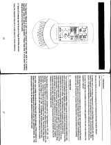
the Weather Station above). Once the batteries are in place, all
segments of the LCD will light up briefly and a short signal tone will
sound. Following the indoor temperature/humidity and the time as
12:00 will be displayed. If these information are not displayed on the
LCD after 60 seconds, remove the batteries and wait for at least 60
seconds before reinserting them. Once the indoor data is displayed
user may proceed to the next step.
3. After the batteries are inserted, the Weather station will start receiving
data signal from the transmitter. The outdoor temperature and
humidity data should then be displayed on the Weather station. If this
does not happen after 2 minutes, the batteries will need to be
removed from both units and reset from step 1.
4. In order to ensure sufficient 915 MHz transmission however, the
distance between the Weather Station and the transmitter should not
be more than 330 feet (100 meters) (see notes on “Positioning” and
“915 MHz Reception”).
Note:
In the event of changing batteries of the units, ensure the batteries do not
spring free from the contacts. Always wait at least 1 minute after removing
the batteries before reinserting, otherwise start up and transmission
problems may occur.
WHEN MORE THAN ONE TRANSMITTER IS USED
1. User shall remove all the batteries from the Weather Station and
transmitters, and wait 60 seconds.
2. Insert the batteries in the first transmitter.
3. Within 2 minutes of powering up the first transmitter, insert the
batteries in the Weather Station. Once the batteries are in place, all
segments of the LCD will light up briefly and a short signal tine will
sound. Following the indoor temperature/humidity and the time as
12:00 will be displayed. If these information are not displayed on the
LCD after 60 seconds, remove the batteries from both units and wait
for at least 60 seconds before reinserting them.
4. The outdoor temperature and humidity data from the first transmitter
(channel 1) should then be displayed on the Weather Station. Also,
the signal reception icon will be displayed. If this does not happen
after 2 minutes, the batteries will need to be removed from both units
24
and reset from step 1.
5. Insert the batteries in the second transmitter as soon as the outdoor
temperature and humidity readings from the first transmitter are
displayed on the Weather Station.
Note :
User shall insert the batteries into the second transmitter
within 45 seconds after the Weather Station displays the information
of the first transmitter.
6. The outdoor temperature and humidity from the second transmitter
and the "channel 2" icon should then be displayed on the Weather
Station. If this does not happen after 2 minutes, the batteries will
need to be removed from all the units and reset from step 1.
7. Insert the batteries in the third transmitter as soon as the "channel 2"
icon and outdoor data are displayed on the Weather Station. Then
within 2 minutes, the channel 3 outdoor data from the third transmitter
will be displayed and the channel icon will shift back to "1" once the
third transmitter is successfully received. If this is not happen, user
shall restart the setting up from step 1.
Note :
User shall insert the batteries into the third transmitter within
45 seconds after the Weather Station displays the information of the
first transmitter. Or immediately after reception of the second
transmitter is finished.
8. In order to ensure sufficient 915 MHz transmission however, the
distance between the Weather Station and the transmitter should not
be more than 330 feet (100 meters) (see notes on “Positioning” and
“915 MHz Reception”).
IMPORTANT:
Transmission problems will arise if the setting for additional sensors is not
followed as described above. Should transmission problems occur, it is
necessary to remove the batteries from all units and start again the set-up
from step 1.
Note:
If the signal reception is not successful on the first frequency of
915MHz for 45 seconds, the frequency is changed to 920MHz and
the learning is tried for another 45 seconds. If it is still not successful
the reception is tried for 45 seconds on 910MHz. This will also be
done during re-synchronization.
When the weather station is receiving the WWVB time signal, the
outdoor transmitter data signal will temporarily not be received by the
weather station. During this short period of time, the outdoor readings
shown on the weather station will not be renewed until the WWVB
time signal is successfully received.
25
TO INSTALL AND REPLACE BATTERIES IN THE WEATHER
STATION
The Weather Station uses 3 x AA, IEC
LR6, 1.5V batteries. To install and replace
the batteries, please follow the steps
below:
1. Insert finger or other solid object in
the space at the bottom center of the
battery compartment and lift up to
remove the cover.
2. Insert batteries observing the correct
polarity (see marking).
3. Replace compartment cover.
TO INSTALL AND REPLACE BATTERIES IN THE THERMO-
HYGRO TRANSMITTER
The Thermo-hygro transmitter uses 2 x AA, IEC, LR6,
1.5V batteries. To install and replace the batteries,
please follow the steps below:
1. Remove the cover.
2. Insert the batteries, observing the correct polarity
(see marking).
3. Replace the battery cover.
Note:
In the event of changing batteries in any of the units, all units need to be
reset by following the setting up procedures. This is due to a random
security code assigned by the transmitter at start-up. This code must be
received and stored by the Weather Station in the first 3 minutes of power
being supplied to the transmitter.
BATTERY CHANGE:
It is recommended to replace the batteries in all units regularly to ensure
optimum accuracy of these units (Battery life see Specifications below).
Please participate in the preservation of the
environment. Return used batteries to an
authorized depot.
RESETTING
The Weather Station and the Thermo-hygro transmitter need to be reset
when one of the following conditions occur:
Unsuccessful 915MHz signal reception.
26
Malfunction on the units.
Batteries replacement.
For resetting, remove all batteries from the units. Wait at least for 1 minute
before powering up the Weather station again. Proceed from step 1 in
“Setting Up”.
ATOMIC TIME - WWVB RADIO CONTROLLED TIME
The NIST (National Institute of Standards and Technology—Time and
Frequency Division) WWVB radio station is located in Ft. Collins, Colorado,
and transmits the exact time signal continuously throughout the United
States at 60 kHz. The signal can be received up to 2,000 miles away
through the internal antenna in the Weather Station. However, due to the
nature of the Earth’s Ionosphere, reception is very limited during daylight
hours. The wireless weather station will search for a signal every night
when reception is best.
The WWVB radio station receives the time data from the NIST Atomic clock
in Boulder, Colorado. A team of atomic physicists is continually measuring
every second, of every day, to an accuracy of ten billionths of a second per
day. These physicists have created an international standard, measuring a
second as 9,192,631,770 vibrations of a Cesium-133 atom in a vacuum.
For more detail, visit http://www.boulder.nist.gov/timefreq.htm. To listen to
the NIST time, call (303)499-7111. This number will connect you to an
automated time, announced at the top of the minute in “Coordinated
Universal Time”, which is also known as Greenwich Mean Time (GMT).
This time does not follow Daylight Saving Time changes. After the top of
the minute, a tone will sound for every second. It is possible that your
wireless weather station will not be exactly on the second due to the
variance in the quartz. However, the clock will adjust the quartz timing over
the course of several days to be very accurate; under 0.10 seconds per
day.
FUNCTION KEYS:
Weather Station:
The Weather Station has 5 easy to use function keys, located on the right
side of the weather station:
27
IN key
OUT/+ key
ALM/DATE key
SET key
SNOOZE/CH key
SET key
Press and hold the key to enter manual setting modes: LCD contrast,
time zone, DST ON/OFF, time reception ON/OFF, 12/24 hour display,
manual time setting, calendar, temperature °C/°F, pressure hPa/inHg,
relative pressure value, and weather icon sensitivity setting
Reset all MIN/MAX records
Stop the alarm during alarm ringing
Stop snooze mode
Back-light on
ALM/DATE key
Press and hold key for 3 seconds to enter the alarm setting mode
Active/de-active the alarm time
Stop the alarm during alarm ringing
Stop snooze mode
Display date
Back-light on
IN key
Press to toggle between MAX/MIN and current indoor
temperature/humidity data
Press to set the alarm hour (inside alarm setting mode)
Decrease relative pressure value (within manual set mode)
Stop the alarm during alarm ringing
Stop snooze mode
Back-light on
28
OUT/+ key
Press shortly to toggle between MAX/MIN and current outdoor
temperature/humidity data
Increase, change, toggle all values in manual set mode
Press to set the alarm minute (inside alarm setting mode)
Stop the alarm during alarm ringing
Stop snooze mode
Back-light on
SNOOZE/CH key
Active snooze function during alarm ringing
Exit the manual set mode and alarm setting mode
Switch among display of channels (if more than 1 transmitter is used)
Back-light on
29
Moon phase icon
Weather tendency
indicator
Calendar or alarm time
Indoor relative
humidity in RH%
Time reception icon
(for WWVB time)
Indoor temperature
in ºC/ ºF
Weather forecast icon
Outdoor data signal
rece
p
tion indicator*
Outdoor temperature in ºC/ ºF
Outdoor relative humidity in RH%
Comfort indicator icon
Relative air pressure
history bar graph
Relative air pressure
in hPa / inHg
Time
LCD SCREEN
The LCD screen is split into 4 sections displaying the information for
time/calendar/alarm/moon phase, indoor data, weather forecast and
outdoor data.
* When the signal is successfully received by the Weather Station, the
outdoor transmission icon will be switched on. (If not successful, the icon
will not be shown on LCD). The user can then easily see whether the last
reception was successful (icon on) or not (icon off). On the other hand, the
short blinking of the icon shows that a reception is currently taking place.
MANUAL SETTINGS:
The following manual settings can be changed when pressing the SET key
for:
LCD contrast setting
Time zone setting
DST ON/ OFF setting (daylight saving time)
Time reception ON/OFF setting
12/24-hour format setting
Manual time setting
Calendar setting
Low battery
indicator
30
°C/°F temperature setting
hPa / inHg pressure setting
Relative air pressure setting
Weather forecasting icon sensitivity setting
LCD CONTRAST SETTING:
The LCD contrast can be set within 8 levels, from LCD 0 to LCD7 (Default
setting is LCD 4):
1. Press and hold the SET key until the digit starts flashing.
2. Use the OUT/+ key to view all levels of contrast.
3. Select the desired LCD contrast. Confirm with the SET key and enter
in the Time Zone setting.
TIME ZONE SETTING:
The time zone default of the Weather Station is “-5h”. To set a different
time zone:
1. The current time zone value starts flashing.
2. Use the OUT/+ key to set the time zone. The range runs from 0 to -12
and then runs from +12 back to 0 in consecutive 1-hour intervals.
3. Confirm with the SET key and enter the Daylight saving time
ON/OFF setting.
DAYLIGHT SAVING TIME ON/ OFF SETTING
Daylight time saving (DST) function can be set ON/OFF. Default setting
“ON”
1. The digit “ON” will start flashing on the LCD.
2. Use the OUT/+ key to turn OFF the daylight time saving function.
3. Confirm with the SET key and enter the Time reception ON/OFF
setting.
Flashing
Last digit flashing
Digit flashing
31
TIME RECEPTION ON/OFF SETTING:
In area where reception of the WWVB time is not possible, the WWVB time
reception function can be turn OFF. The clock will then work as a normal
Quartz clock. (Default setting is ON).
4. The digit “ON” will start flashing on the LCD.
5. Use the OUT/+ key to turn OFF the time reception function.
6. Confirm with the SET key and enter the 12/24-hour format setting.
Note:
If the Time Reception function is turn OFF manually, the clock will not
attempt any reception of the WWVB time as long as the Time
Reception OFF function is activated.
The time reception icon and the WWVB” icon will not be displayed
on the LCD.
12/24-HOUR FORMAT SETTING:
The hour display can be selected to show hours in 12-hour or 24-hour
settings. (Default 12-Hour)
1. Use the OUT/+ key to toggle between “12H” or “24H”.
2. Confirm with the SET key and enter the Manual time setting.
MANUAL TIME SETTING:
In case the Weather Station cannot detect the WWVB-signal (for example
due to disturbances, transmitting distance, etc.), the time can be manually
set. The clock will then work as a normal Quartz clock.
1. The hour digit will start flashing.
2. Use the OUT/+ key to set the hour.
Hour flashing
Minutes flashing
Flashing
Flashing
32
3. Press again the SET key to set the minutes. The minute digits start
flashing.
4. Use the OUT/+ key to set the minutes.
5. Confirm with the SET key and enter the Calendar setting.
Note:
The unit will still try to receive the signal between 0:00 and 6:00 am every
day despite it being manually set, if the WWVB reception function has been
set ON. When it does receive the signal, it will change the manually set
time into the received time. During reception attempts the WWVB tower
icon will flash. If reception has been unsuccessful, then the WWVB tower
icon will not appear but reception will still be attempted the following hour.
CALENDAR SETTING:
The date default of the Weather station is 1. 1. 2006. Once the radio-
controlled time signals are received, the date is automatically updated.
However, if the signals are not received, the date can also be set manually.
1. The year starts flashing.
2. Use the OUT/+ key to set the year (between year 2003-2029).
3. Press the SET key again to confirm and to enter the month setting.
The month starts flashing.
4. Use the OUT/+ key to set the month.
5. Press the SET key again to confirm and to enter the date setting
mode. The date starts flashing.
6. Use the OUT/+ key to set the date.
7. Confirm all calendar settings with the SET key and enter the
Temperature unit setting.
°C/°F TEMPERATURE SETTING:
The temperature display can be selected to show temperature data in °C or
°F (Default °F).
1. Use the OUT/+ key to toggle between “°C” or “°F”.
Year
Date and month (24hr time format)
Month and date (12hr time format)
Flashing
33
2. Confirm with the SET key and enter the Air pressure unit setting.
hPa / inHg PRESSURE UNIT SETTING:
The pressure display can be selected to show relative air pressure in hPa
or inHg (default is “inHg”).
1. Use the OUT/+ key to toggle between “hPa” or “inHg” unit.
2. Confirm with the SET key and enter the Relative air pressure value
setting.
Note: Units of weather icon sensitivity and air pressure history are not
affected. They are always expressed in hPa.
RELATIVE AIR PRESSURE VALUE SETTING
The default relative pressure value is 29.92 inHg (1013 hPa). This can be
manually set to another value within the range of 28.35 – 30.72 inHg (960 –
1040 hPa) for a better reference.
1. The current relative pressure value will start flashing
2. Use the OUT/+ key to increment and IN key to decrement the value.
3. Keep holding the key allows the value to advance faster.
4. Confirm with the SET key and enter the Weather forecast icon
sensitivity setting.
WEATHER FORECASTING ICON SENSITIVITY SETTING:
For locations with rapid changes of weather conditions, the weather icons
sensitivity can be set to a different level for faster display of weather
conditions.
Flashing
Flashing
Flashing
34
1. The current sensitivity value will start flashing.
2. Use the OUT/+ key to set the weather sensitivity level. There are 3
levels of setting: 2, 3 and 4. The value corresponds to the change of
air pressure in hPa before the weather icon will switch to another
state. Level 2 is the most sensitive setting, level 4 is the slowest
recording setting (default setting is "3").
3. Confirm with the SET key and exit the Manual settings.
TO EXIT THE MANUAL SETTING MODE
To exit the manual setting mode anytime during the manual setting, press
the SNOOZE/CH key or wait for automatic timeout. The mode will return to
normal time display.
ALARM SETTING:
The alarm time can be set when pressing the ALM/DATE key.
1. Press and hold the ALM/DATE key to enter the alarm set mode. The
alarm digits flash.
2. Use the IN key to set the alarm hour.
3. Use the OUT/+ key to set the alarm minute.
4. Confirm with SNOOZE/CH key and exit the Alarm setting. The icon
(()) will be displayed along with the set alarm time.
Note:
If the calendar is displayed in the Weather station, the alarm is NOT active.
To view and active the alarm, press the ALM/DATE key. The alarm icon
and the alarm time will be displayed, indicating that the alarm setting is
activated.
The maximum alarm ring duration is 2 minutes.
SNOOZE SETTING AND STOPPING THE ALARM:
10 minutes snooze function can be set when the alarm is ringing by
pressing the SNOOZE/CH key.
When the alarm is snoozing, the alarm icon (()) will remain flashing
indicating that the alarm is active but is in Snooze mode. To stop the
snooze function when it is in snooze period, press any key except the
SNOOZE/CH key.
To stop the alarm, press any key during alarm ringing, except the
SNOOZE/CH key.
Alarm icons
Alarm time
35
MOON PHASES SYMBOL
The Moon icon of the Weather station will also display all 12 Moon phases
throughout the year according to the set calendar.
INDOOR RELATIVE HUMIDITY AND INDOOR
TEMPERATURE:
The indoor temperature and humidity data, the indoor comfort indicator are
automatically updated and displayed on the second section of the LCD.
THE COMFORT LEVEL INDICATOR:
Comfortable : A happy face icon “” indicating a temperature level
between 20°C and 25.9°C and relative humidity
reading between 45% and 65%.
Uncomfortable : A sad face icon “” indicating any value outside the
comfortable range.
TOGGLING AND RESETTING THE INDOOR READINGS:
1. Press the IN key to toggle between the indoor current, MAX/MIN
temperature and humidity data. The time and dates of the recorded
data will also be displayed in the time and calendar sections (for
temperature data only).
Once to show the MAX indoor temperature and humidity data with
the recorded time and date.
Twice to show the MIN indoor temperature and humidity data with
the recorded time and date.
Three times to return to the current displayed values
Indoor relative
humidity in RH%
Indoor temperature
in °C or ºF
MAX icon
New
Moon
Small
Waxing
Crescent
Large
Waxing
Crescent
First
Quarter
Small
Waxing
Gibbous
Large
Waxing
Gibbous
Small
Waning
Crescent
Large
Waning
Crescent
Last
Quarter
Small
Waning
Gibbous
Large
Waning
Gibbous
Full Moon
36
FORECAST
FORECAST
FORECAST
2. Once the MIN or MAX data is displayed, press and hold the SET key
for 3 seconds to reset the respective MIN or MAX record to current
temperature and humidity data, and current time, date display.
Note: The MIN or MAX data needs to be reset individually.
WEATHER FORECAST AND WEATHER TENDENCY:
WEATHER FORECASTING ICONS:
Weather icons in the third section of LCD can be displayed in any of the
following combinations:
Sunny Cloudy with sunny intervals Rainy
For every sudden or significant change in the air pressure, the weather
icons will update accordingly to represent the change in weather. If the
icons do not change, then it means either the air pressure has not changed
or the change has been too slow for the Weather station to register.
However, if the icon displayed is a sun or raining cloud, there will be no
change of icon if the weather gets any better (with sunny icon) or worse
(with rainy icon) since the icons are already at their extremes.
The icons displayed forecasts the weather in terms of getting better or
worse and not necessarily sunny or rainy as each icon indicates. For
example, if the current weather is cloudy and the rainy icon is displayed, it
does not mean that the product is faulty because it is not raining. It simply
means that the air pressure has dropped and the weather is expected to
get worse but not necessarily rainy.
Note:
After setting up, readings for weather forecasts should be disregarded for
the next 12-24 hours. This will allow sufficient time for the Weather station
to collect air pressure data at a constant altitude and therefore result in a
more accurate forecast.
Common to weather forecasting, absolute accuracy cannot be guaranteed.
The weather forecasting feature is estimated to have an accuracy level of
about 75% due to the varying areas the Weather station has been
designed for use. In areas that experience sudden changes in weather (for
example from sunny to rain), the Weather station will be more accurate
compared to use in areas where the weather is stagnant most of the time
(for example mostly sunny).
If the Weather station is moved to another location significantly higher or
lower than its initial standing point (for example from the ground floor to the
upper floors of a house), discard the weather forecast for the next 12-24
37
hours. By doing this, the Weather Station will not mistake the new location
as being a possible change in air-pressure when really it is due to the slight
change of altitude.
WEATHER TENDENCY INDICATOR
Working together with the weather icons is the weather tendency indicators
(located on the left and right sides of the weather icons). When the
indicator points upwards, it means that the air-pressure is increasing and
the weather is expected to improve, but when indicator points downwards,
the air-pressure is dropping and the weather is expected to become worse.
Taking this into account, one can see how the weather has changed and is
expected to change. For example, if the indicator is pointing downwards
together with cloud and sun icons, then the last noticeable change in the
weather was when it was sunny (the sun icon only). Therefore, the next
change in the weather will be cloud with rain icons since the indicator is
pointing downwards.
Note:
Once the weather tendency indicator has registered a change in air
pressure, it will remain permanently visualized on the LCD.
AIR PRESSURE HISTORY (ELECTRONIC BAROMETER WITH
BAROMETRIC PRESSURE TREND)
The third section of the LCD also shows the relative air pressure value and
the air pressure history.
The bar chart indicates the air pressure history trend over the last 24 hours
in 7 steps, 0h, -3h, -6h, -9h, -12h, -18h, and -24h. The “0h” represents the
current full hour air pressure recording. The columns represent the “hPa”
(0, ±2, ±4, ±6) at specific time. The “0” in the middle of this scale is equal to
the current pressure and each change (±2, ±4, ±6) represents how high or
low in “hPa“ the past pressure was compared to the current pressure.
If the bars are rising it means that the weather is getting better due to the
increase of air pressure. If the bars go down, it means the air pressure has
dropped and the weather is expected to get worse from the present time
“0h“.
Note:
For accurate barometric pressure trends, the Weather Station should
operate at the same altitude for example, it should not be moved from the
Air pressure over the last 24 hours
38
ground to the second floor of the house. Should the unit be moved to a new
location, discard readings for the next 12-24 hours.
OUTDOOR TEMPERATURE/HUMIDITY DATA
The fourth LCD section shows the outdoor temperature and humidity, the
reception indicator, the transmitter identification number and the MIN/MAX
outdoor data.
TOGGLING AND RESETTING THE OUTDOOR DATA
1. To toggle between the outdoor current, MAX/MIN temperature and
humidity data and the times (for temperature data only) they were
recorded press the OUT/+ key:
Once to show the MAX outdoor temperature and humidity data with
the recorded time and date.
Twice to show the MIN outdoor temperature and humidity data with
the recorded time and date.
Three times to return to the current displayed values.
2. Once the MIN or MAX data is displayed, press and hold the SET key
for 3 seconds to reset the respective MIN or MAX record to current
temperature and humidity data, and current time, date display.
Note: The MIN or MAX data needs to be reset individually.
TO VIEW THE MIN/MAX DATA FROM DIFFERENT
TRANSMITTERS
When more than 1 transmitter used:
1. To toggle between transmitters, press the SNOOZE/CH key:
Once to show transmitter 2
Twice to show transmitter 3
Three times to return to transmitter 1
2. Use OUT/+ key to view the MIN/MAX temperature and humidity data
for the selected transmitter.
3. To reset the minimum and maximum temperature and humidity data,
and the times at which they were recorded, press the SET key
continuously for about 3 seconds. This will reset the MIN/MAX data
recorded to the current time, date, temperature and humidity. The
current time taken is the normal displayed time and does not regard
the time zone set for the unit.
Note: the MIN/MAX data for each transmitter needs to be reset separately.
Outdoor
temperature
in °C/ °F
Outdoor relative
humidity in RH%
Outdoor transmitter identification number
MIN icon
  • Page 1 1
  • Page 2 2
  • Page 3 3
  • Page 4 4
  • Page 5 5
  • Page 6 6
  • Page 7 7
  • Page 8 8
  • Page 9 9
  • Page 10 10
  • Page 11 11
  • Page 12 12
  • Page 13 13
  • Page 14 14
  • Page 15 15
  • Page 16 16
  • Page 17 17
  • Page 18 18
  • Page 19 19
  • Page 20 20
  • Page 21 21
  • Page 22 22
  • Page 23 23
  • Page 24 24
  • Page 25 25
  • Page 26 26
  • Page 27 27
  • Page 28 28
  • Page 29 29
  • Page 30 30
  • Page 31 31
  • Page 32 32
  • Page 33 33
  • Page 34 34
  • Page 35 35
  • Page 36 36
  • Page 37 37
  • Page 38 38
  • Page 39 39
  • Page 40 40
  • Page 41 41
  • Page 42 42
  • Page 43 43
  • Page 44 44
  • Page 45 45
  • Page 46 46
  • Page 47 47
  • Page 48 48
  • Page 49 49
  • Page 50 50
  • Page 51 51
  • Page 52 52
  • Page 53 53
  • Page 54 54
  • Page 55 55
  • Page 56 56
  • Page 57 57
  • Page 58 58
  • Page 59 59
  • Page 60 60
  • Page 61 61
  • Page 62 62
  • Page 63 63
  • Page 64 64
  • Page 65 65
  • Page 66 66
  • Page 67 67
  • Page 68 68
  • Page 69 69
  • Page 70 70
  • Page 71 71
  • Page 72 72
  • Page 73 73
  • Page 74 74
  • Page 75 75
  • Page 76 76
  • Page 77 77
  • Page 78 78
  • Page 79 79
  • Page 80 80
  • Page 81 81
  • Page 82 82
  • Page 83 83
  • Page 84 84
  • Page 85 85
  • Page 86 86
  • Page 87 87
  • Page 88 88
  • Page 89 89
  • Page 90 90
  • Page 91 91
  • Page 92 92
  • Page 93 93
  • Page 94 94
  • Page 95 95
  • Page 96 96
  • Page 97 97
  • Page 98 98
  • Page 99 99
  • Page 100 100
  • Page 101 101
  • Page 102 102
  • Page 103 103
  • Page 104 104
  • Page 105 105
  • Page 106 106
  • Page 107 107
  • Page 108 108
  • Page 109 109
  • Page 110 110
  • Page 111 111
  • Page 112 112
  • Page 113 113
  • Page 114 114
  • Page 115 115
  • Page 116 116
  • Page 117 117
  • Page 118 118
  • Page 119 119
  • Page 120 120
  • Page 121 121
  • Page 122 122
  • Page 123 123
  • Page 124 124
  • Page 125 125
  • Page 126 126
  • Page 127 127
  • Page 128 128
  • Page 129 129
  • Page 130 130
  • Page 131 131
  • Page 132 132
  • Page 133 133
  • Page 134 134
  • Page 135 135
  • Page 136 136
  • Page 137 137
  • Page 138 138
  • Page 139 139
  • Page 140 140
  • Page 141 141
  • Page 142 142
  • Page 143 143
  • Page 144 144
  • Page 145 145
  • Page 146 146
  • Page 147 147
  • Page 148 148
  • Page 149 149

LA CROSS TECHNOLOGY WS-9037U-IT User manual

Category
Weather stations
Type
User manual

Ask a question and I''ll find the answer in the document

Finding information in a document is now easier with AI