3M Buffers Operating instructions

Category
Power tools
Type
Operating instructions

This manual is also suitable for

3M 3 in. Random Orbital Buffer 1 Revision 061009
Intended Use
RANDOM ORBITAL BUFFER INSTRUCTION MANUAL
3 in (77 mm) 11,000 RPM
Important Safety Information
Please read, understand and follow all safety information contained in these instructions prior to the use of this tool. Retain these
instructions for future reference.
This pneumatic tool is intended for use in industrial locations, and used only by skilled, trained professionals in accordance with the in-
structions in this manual. It is designed to be used with the disc pad, and appropriate 3M foam buffing pads and with appropriate buffing
or polishing compounds for buffing metals, wood, stone, plastics and other materials. It should only be used for such buffing applications
and within marked capacity and ratings. Only accessories specifically recommended by 3M should be used with this tool. Use in any
other manner or with other accessories could lead to unsafe operating conditions.
Do not operate tool in water or in an excessively wet application.
Do not use disc pads that have a Max RPM less than the tool Max RPM rating.
To reduce the risks associated with impact from abrasive product, disc pad, or tool breakup, sharp edges, hazardous
pressure, rupture, vibration and noise:
• Read, understand and follow the safety information contained in these instructions prior to the use of this tool. Retain these
instructions for future reference.
• Only personnel who are properly trained should be allowed to service this tool.
• Practice safety requirements. Work alert, have proper attire, and do not operate tools under the influence of alcohol or drugs.
• Operators and other personnel must always wear protection for eyes, ears, and respiratory protection when in the work area or
while operating this product. Follow your employer’s safety policy for PPE’s and/or ANSI Z87.1 or local/national standards for
eyewear and other personal protective equipment requirements.
• Wear protective apparel, taking into consideration the type of work being done.
• Never exceed marked maximum input pressure (90psi / .62Mpa / 6.2Bars).
• Proper eye protection must be worn at all times.
Tool shall not be operated in the presence of bystanders.
• If you notice any abnormal noise or vibration when operating the tool, immediately discontinue its use and inspect for worn or
damaged components. Correct or replace the suspect component. If abnormal noise or vibration still exists, return the tool to 3M
for repair or replacement. Refer to warranty instructions.
• Never operate this tool without all safety features in place and in proper working order.
• Never over-ride or disable the safety features of the start-stop control such that it is in the on position.
• Make sure the tool is disconnected from its air source before servicing, inspecting, maintaining, cleaning, and before changing
abrasive product.
• Prior to use, inspect abrasive product and accessories for possible damage. If damaged, replace with new abrasive product and
accessories available from 3M.
• Only use accessories supplied or recommended by 3M.
• Never allow this tool to be used by children or other untrained people.
• Do not leave an unattended tool connected to air source.
WARNING
Explanation of Signal Word Consequences
Indicates a potentially hazardous situation which, if not avoided, may result in death or serious injury
and/or property damage.
Indicates a potentially hazardous situation which, if not avoided, may result in minor or moderate
injury and/or property damage.
WARNING:
CAUTION:
Original Instructions
3M 3 in. Random Orbital Buffer 2 Revision 061009
To reduce the risks associated with vibration:
• If any physical hand/wrist discomfort is experienced, work should be stopped promptly to seek medical attention. Hand, wrist and arm
injury may result from repetitive work, motion and overexposure to vibration.
To reduce the risks associated with loud noise:
• Always wear hearing protection while operating this tool. Follow your employer’s safety policy or local/national standards for personal
protective equipment requirements.
To reduce the risks associated with fire or explosion:
• Do not operate the tool in explosive atmospheres, such as in the presence of flammable liquids, gases, or dust. The abrasives are able to
create sparks when working material, resulting in the ignition of the flammable dust or fumes.
• Refer to MSDS of the material being worked as to potential for creating fire or explosion hazard.
To reduce the risks associated with hazardous dust ingestion or eye/skin exposure:
• Use appropriate respiratory, skin protection, and/or local exhaust as stated in the MSDS of the compound used and of the material
being worked on.
To reduce the risks associated with hazardous voltage:
• Do not allow this tool to come into contact with electrical power sources as the tool is not insulated against electrical shock.
To reduce the risks associated with skin abrasion, burns, cuts, or entrapment:
• Keep hands, hair, and clothing away from the rotating parts of the tool.
• Wear suitable protective gloves while operating tool.
• Do not touch the rotating parts during operation for any reason.
• Do not force tool or use excessive force when using tool.
To reduce the risk associated with whipping or hazardous pressure-rupture:
• Ensure supply hose is oil resistant and is properly rated for required working pressure.
• Do not use tools with loose or damaged air hoses or fittings.
• Be aware that incorrectly installed hoses and fittings might unexpectedly come loose at any time and create a whipping/impact hazard.
To reduce the risk associated with fly off of abrasive product or parts:
• Use care in attaching, backup pad; following the instructions to ensure that they are it is securely attached to the tool before use.
• Never over-tighten accessory fasteners.
CAUTION!
Parts Page
RAG 03/04/09 MDR 03/04/09
-RELEASE FOR PRODUCTION
A
DESCRIPTION / DATE
R
REVISION RECORD
SCREW, BUTTON HEAD TORX M4.0 X 15 mm BLACK 2
1YL
BM
ES
S
A
G
NIH
S
U
BT
ELN
I
T
P
N81
-
4
/
131
00
AP
X0
6
1G
NI
R-Omm
87
.
1
xmm
6.
7
9
050APX
8
5
59 XPA1398
Y
T
Q
N
OI
T
P
I
R
C
S
ED
N
/
P
TI
1G
N
I
R
G
N
I
NI
A
T
E
RL
A
N
R
E
T
XE040
0
A
P
X
1
1
SD
L
E
IH
S
2
-
GN
IR
A
E
B
8
X
6
2
X
0
1
1
2
0
0
AP
X
2
1
ET
A
LPDNERA
E
R
33
8
1A
P
X
3
1
GN
IR
-
O
m
m0
.
2
xm
m
5
2
40
0
AP
X
4
1
YL
B
M
E
SSA
RE
D
N
ILY
C
57
12
A
PX
5
1RO
TO
R
DEN
I
HC
AM
5
0
0
0
BP
X
6
5E
N
AV
0
100
AP
X
7
1
Y
EK
F
FU
R
D
O
OW
m
m31x
mm
31400AP
X
8
1
ET
A
L
P
D
N
ET
NO
R
F
23
8
1
A
P
X
9
1
S
D
L
EIH
S2
-
GNI
RA
E
B
8
X8
2
X2
1
9
1
0
0
A
P
X
0
1
1
GN
I
R
-
Omm
1
.
3
xm
m4
.
9354
0
0
A
PX
1
1
1
D
AERHT
MM
0
5-
G
N
I
R
K
CO
L
3
99
1
AP
X2
1
13 XPB0479 3 in. x 1/2 in. ORBIT AirSHIELD™ SHAFT BALANCER - 20.0 mm MOTOR 1
1
R
ET
L
IF
2
2
1
0AP
X
4
1
1EV
L
A
V
K
CE
H
C
L
LI
B
KC
U
D
1
21
0
A
P
X
5
1
1
RE
N
I
A
T
ER
E
V
LAV
0
2
1
0
A
P
X
6
1
17 XPA0090 11.9 mm (15/32 in
1
G
NI
R
G
NI
N
I
A
T
E
R).
18 XPA0938 12 x 28 x 16 DOUBLE ROW ANGULAR CONTACT BEARING - 1 SEAL 1
1K
H
T2.0x
D
O0
.
81x
D
I
1.21
R
E
C
A
PS
6
1
0
0
APX91
1REH
SAW
EL
L
I
VE
LL
E
B
71
0
0
AP
X
0
2
1
EL
D
NI
PS
2130
B
PX1
2
1
D
E
R58
4SMP
-
M
3
R
O
F
H
C
N
E
RW
D
A
P
mm71
6
77
1
A
P
X
22
1G
N
IRG
N
INIATER
8
1
00
APX
3
2
24 N/A 1 Back-up Pad supplied with each tool (type determined by model) 1
1
l
o
ot
h
c
a
e
h
t
iw
dei
l
p
p
u
s
to
n
si
d
a
P
g
nif
f
u
BA
/N
5
2
1
C
5
8
4S
MP
-
RE
G
N
A
HD
N
A
H
o
w
T
45
91
APX
6
2
2
D
E
R
5
8
4
S
MP-
G
U
L
P
DE
DA
E
R
H
T
8
M
5591
AP
X
72
2G
N
I
RR
E
CA
P
S
5
6
81
A
PX82
1RE
F
F
U
B-
D
UO
R
H
S
CAV
-
N
O
N
W
L.n
i3
8
0
5
0
BPX92
30 XPB0390 MACHINED DIE-CAST
1
RE
F
F
UB
-
G
NIS
U
O
H
R
O
T
OM
1NIP
G
NI
R
PS
R
E
D
N
I
L
Y
C
4000
A
PX1
3
1
E
V
E
EL
S
EVLAV
5100
A
P
X
23
1
R
E
FF
U
B-
YL
BM
E
SS
A
M
E
T
S
E
V
LA
V
5
99
1
A
P
X33
1
GN
IR
-
O
m
m
5
.
1
xmm934
0
0
A
P
X
4
3
1
584SM
P-LO
R
T
N
O
C
D
E
EP
S
D
N
A
Ho
w
T
HS
UL
F
4222
APX5
3
1
G
N
IR
G
N
I
N
IATERL
A
N
R
ET
N
I
9
3
00
APX
6
3
T
POEL
D
NA
H
EDI
S
M3
0
6
9
1
APX73
1R
EF
FUB
-
TE
K
SAG
2
9
9
1
A
PX
8
3
1R
E
FFU
B
-
E
LZ
ZO
NT
S
U
A
H
X
EROTO
M
7
8
3
0
B
P
X9
3
3
WERC
SP
A
CD
A
E
H
NOTT
U
BT
EKCOS
XEH
8
X
4
M
4
6
6
0
A
P
X0
4
1
HTD
IW
m
m3.1X.
D
.I
mm
0.11,
GNI
R
-O
4112
A
PX1
4
1T
A
ESEVLAV
9000
A
P
X
24
1E
VLA
V
7000
A
PX3
4
1G
N
I
R
PS
E
VL
A
V
41
00
AP
X44
1Y
L
BM
E
S
S
A
L
A
E
S
EN
I
LRI
A
0
3
7
0
A
PX
5
4
1REFFUB
-G
N
I
B
UTT
E
LN
I
6
5
9
1AP
X6
4
4
W
ERC
S
P
AC
DA
EH
N
OTTU
B
TE
KC
O
S5
2
x
4
M
2
1
5
0
A
P
X
7
4
4
M
M
4TRE
S
N
IDED
A
E
R
HT
1
7
0
0
A
P
X8
4
1R
E
FFUB
-
E
L
DN
A
H
5
2
3
0
C
P
X9
4
1
R
E
F
FUB-
P
I
RGE
L
I
TPERG
7
6
00DPX05
51 XPA2079 3M ROB 11,000 RPM 12.0 mm (1/2 in.) ORBIT THROTTLE LEVER 1
1)sen
i
hc
aMM
PR
00
0,0
1
r
o
f(TRESN
I
RE
L
FFUM
3
4
0
2
A
PX
2
5
1
REF
FUB-
R
E
L
F
F
UM
47
12
A
P
X35
1
H
T
D
IW
m
m0.1X
.D
.Im
m
0.91
,G
NIR
-O
1802
AP
X
45
1
R
EF
F
UB
,P
AC
TS
U
A
H
XE
54
40
B
P
X
55
1D
E
R
5
84
S
M
P
-
P
AC
DN
ET
SUAH
XE
/TELNI
2
5
9
1AP
X
6
5
1
GNI
RE
V
I
T
PAC
TELN
I
0
150
A
PX
7
5
ITEM NO. TORQUE SETTINGS in.-lbs (N-m)
12 55 - 65 (6.2 - 7.3)
40 21 - 30 (2.4 - 3.4)
47 20 - 25 (2.2 - 2.8)
59 27 - 30 (3.0 - 3.4)
60 60 - 72 (6.8 - 8.1)
40
41
42
43
44
46
45
56
22
1
2
3
5
4
7
6
8
9
10
11
12
13
14
15
16
17
18
19
38
20
39
48
21
23
25
24
51
33
32
50
53
54
55
59
60
58
57
49
30
31
27
28
26
28
27
37
29
34
35
36
47
52
PERMISSION OF X'POLE PRECISION TOOLS INC. IS PROHIBITED.
DRWN BY / DATE
MATERIAL
PROPRIETARY AND CONFIDENTIAL
PROPERTY OF X'POLE PRECISION TOOLS INC. ANY REPRO-
STD TOL
0.1
PRECISION
X'POLE
0.5°
XX/XX +/-
TOOLS INC.
RAG
03/04/09
.XX +/-
DUCTION IN PART OR AS A WHOLE WITHOUT THEW RITTEN
03/04/09
SEE BOM
ENG APP / DATE
ANGLES +/-
CKD BY / DATE
0.05
NA
NA
MDR
XPC0332
P/N
TITLE
.X +/-
THE INFORMATION CONTAINED IN THIS DRAWING IS THE SOLE
.XXX +/-
3M 3 in. (77 mm) x 1/2 in. (12 mm) ORBIT, 11,000
RPM RANDOM ORBITAL BUFFER PARTS PAGE
3M 3 in. Random Orbital Buffer 3 Revision 061009
Parts List
IT 3M P/N 3M UPC P/N DESCRIPTION QTY
1 A0040 28113 RETAINING RING 1
2 A0021 28107 BEARING 1
3 30327 30327 REAR ENDPLATE 1
4 A0042 28115 O-RING 1
5 30347 30347 CYLINDER ASSEMBLY 1
6 B0005 28170 ROTOR 1
7 A0010 28099 VANE 5
8 A0041 28114 WOODRUFF KEY 1
9 30326 30326 FRONT ENDPLATE 1
10 A0019 28106 BEARING 1
11 A0045 28118 O-RING 1
12 30337 30337 LOCK RING - 50 MM THREAD 1
13 30361 30361 SHAFT BALANCER 1
14 A0122 28132 FILTER 1
15 A0121 28131 DUCKBILL CHECK VALVE 1
16 A0120 28130 VALVE RETAINER 1
17 A0090 28127 RETAINING RING 1
18 A0938 28148 BEARING 1
19 A0016 28103 SPACER 1
20 A0017 28104 BELLEVILLE WASHER 1
21 B0312 28183 SPINDLE 1
22 A0146 28134 17 mm PAD WRENCH 1
23 A0018 28105 RETAINING RING 1
24 20350 20350 3M™ Hookit™ Clean Sanding Disc Pad- 3” x 1/2” x 1/4-20 Ext. 1
25 Various Various Finesse-it™ Foam Bufng Pad (3.25” or 3.75” Diameter) 1
26 30331 30331 HANGER 1
27 30332 30332 M8 THREADED PLUG 2
28 30328 30328 SPACER RING 2
29 30362 30362 SHROUD 1
30 30359 30359 MOTOR HOUSING 1
31 30300 30300 SPRING PIN 1
32 A0015 28102 VALVE SLEEVE 1
33 30338 30338 VALVE STEM ASSEMBLY 1
34 A0043 28116 O-RING 1
35 30348 30348 FLUSH SPEED CONTROL 1
36 A0039 28112 RETAINING RING 1
37 30334 30334 SIDE HANDLE OPT
38 30336 30336 GASKET 1
39 30357 30357 MOTOR EXHAUST NOZZLE 1
40 30314 30314 SCREW 3
41 30344 30344 O-RING 1
42 A0009 28098 VALVE SEAT 1
43 A0007 28096 VALVE 1
44 A0014 28101 VALVE SPRING 1
45 30315 30315 AIRLINE SEAL ASSEMBLY 1
46 30333 30333 INLET TUBING 1
47 30308 30308 SCREW 4
48 30301 30301 THREADED INSERT 4
49 30364 30364 HANDLE 1
50 30365 30365 GRIP 1
51 30342 30342 THROTTLE LEVER 1
52 30339 30339 MUFFLER 1
53 30346 30346 MUFFLER 1
54 30343 30343 O-RING 1
55 30360 30360 EXHAUST CAP 1
56 30329 30329 INLET/EXHAUST END CAP 1
57 30306 30306 INLET CAPTIVE RING 1
58 30305 30305 O-RING 1
59 30321 30321 SCREW 2
60 A0013 28100 1/4-18 NPT INLET BUSHING ASSEMBLY 1
3M 3 in. Random Orbital Buffer 4 Revision 061009
Recommended Airline
Size - Minimum
10 mm 3/8 in
Recommended Maximum
Hose Length
8 meters 25 feet
Air Pressure
Maximum Working Pressure 6.2 bar 90 psig
Recommended Minimum NA NA
Product Configuration/Specifications: 11,000 RPM Random Orbital Buffer
* Declared noise levels; measurements carried out in accordance with standard EN ISO 15744:2002.
** Declared vibration levels in accordance with EN12096; measurements carried out in accordance with standard EN ISO 8662-8:1997
except that feed force was reduced to 10N +/- 5N due to the impracticality of operating this small tool at 30N +/- 5N as stated in the
standard.
IMPORTANT NOTE: The noise and vibration values stated in the table are from laboratory testing in conformity with stated codes and
standards and are not sufficient risk evaluation for all exposure scenarios. The actual exposure values and amount of risk or harm
experienced to an individual is unique to each situation and depends upon the surrounding environment, the way in which the individual
works, the particular material being worked, work station design, as well as upon the exposure time and the physical condition of the
user. 3M cannot be held responsible for the consequences of using declared values instead of actual exposure values for any individual
risk assessment.
Operating / Maintenance instructions
PRIOR TO THE OPERATION
The tool is intended to be operated as a hand held tool. It is always recommended that while using the tool, operators stand on a
solid floor, in a secure position with a firm grip and footing. Be aware that the sander can develop a torque reaction. See the section
“SAFETY PRECAUTIONS”.
Use a clean lubricated air supply that will give a measured air pressure at the tool of 6.2 bar (90 psig) when the tool is running with the
lever fully depressed. It is recom¬mended to use an approved 10 mm (3/8 in) x 8 m (25 ft) maximum length airline. Connect the tool
to the air supply as shown in Figure 1. Do not connect the tool to the airline system without an easily accessible air shut off valve. It is
strongly recommended that an air filter, regulator and lubricator (FRL) be used as shown in Figure 1as this will supply clean, lubricated
air at the correct pressure to the tool. In any case appropriate air pressure regulators shall be used at all times while operating this tool
where the supply pressure exceeds the marked maximum of the tool. Details of such equipment can be obtained for your tool distribu-
tor. If such equipment is not used, the tool should be manually lubricated. To manually lubricate the tool, disconnect the airline and put
2 to 3 drops of suitable pneumatic motor lubricating oil such as 3MTM Air Tool Lubricant PN 20451, Fuji Kosan FK-20, Mobil ALMO 525
into the hose end (inlet) of the tool. Reconnect tool to the air supply and run tool slowly for a few seconds to allow air to circulate the oil.
If the tool is used frequently, lubricate it on a daily basis or lubricate it if the tool starts to slow or lose power. It is recommended that the
air pressure at the tool be 6.2 bar (90 psig) while the tool is running so the maximum RPM is not exceeded. The tool can be run at lower
pressures but should never be run higher than 6.2 bar (90 psig). If run at lower pressure the performance of the tool is reduced
Model
Number
Orbit
Pad
Size
mm (in.)
Pad
Part
Num-
ber
Product
Net Wt kg
(lb)
Height
mm (in.)
Length
mm (in.)
*Noise
Level dBA
Pressure
(Power)
**Vibration
Level m/s
2
(ft/s
2
)
**Uncertainty
K
m/s
2
28333
12 mm
(
15
/32 in.)
77 (3) 20350 0.82 (1.8)
99.6
(3.92)
233.2
(9.18)
78 (87) 3.8 (12.5) 0.539
3M 3 in. Random Orbital Buffer 5 Revision 061009
Safety Precautions
1. Read all instructions before using this tool. All operators
must be fully trained in its use and aware of these safety
rules.
2. The tool RPM should be checked on a regular basis to
ensure proper operating speed.
3. Make sure the tool is disconnected from the air supply.
Select a suitable buff pad and secure it to the disc pad.
Be careful to center the buff pad on the disc pad.
4. Always wear required safety equipment when using this
tool.
5. When sanding/buffing always start the tool on the work-
piece. This will prevent gouging due to excess speed of
the buff pad. Stop air flow to the tool as it is removed from
the workpiece.
6. Always remove the air supply to the buffer before fitting,
adjusting or removing the buff pad or disc pad.
7. Always adopt a firm footing and grip and be aware of
torque reaction developed by the buffer.
8. Use only 3M approved spare parts.
9. Always ensure the material being sanded is firmly fixed to
avoid movement.
10. Check hose and fittings regularly for wear. Do not carry
the tool by its hose; always be careful to prevent the tool
from being started when carrying the tool with the air
supply connected.
11. Dust can be highly combustible.
12. If tool is serviced or rebuilt check to ensure that the
maximum tool RPM is not exceeded and that there is no
excessive tool vibration.
13. Do not exceed maximum recommended air pressure.
Use safety equipment as recommended.
14. Prior to installing any sanding or polishing accessory,
always check that it’s marked maximum operating speed
is equal or higher than the rated speed of this tool.
15. The tool is not electrically insulated. Do not use where
there is a possibility of contact with live electricity, gas
pipes, and/or water pipes.
16. This tool is not protected against hazards inherent in
grinding and cutting operations, and no such accessories
should ever be attached.
17. Take care to avoid entanglement with the moving parts
of the tool with clothing, ties, hair, cleaning rags or loose
hanging objects. If entangled, stop air supply immediately
to avoid contact with moving tool parts.
18. Keep hands clear of the spinning pad during use.
19. If the tool appears to malfunction, remove from use im-
mediately and arrange for service and repair.
20. Do not allow the tool to free spin without taking precau-
tions to protect any persons or objects from the loss of
the abrasive or pad ruptures.
21. Immediately release the start handle in the event of any
disruption of pressure; do not attempt to re-start until the
disruption has been corrected.
22. When tool is not in use, store in a clean, dry environment
free of debris.
23. Recycle or dispose of tool according to Local, State, and
Federal regulations.
3M™ Disc and Buffing Pads
3M disc and buff pads are perfectly mated for use on the
3M Buffer. Constructed from premium, industrial-quality
materials and featuring a riveted fiberglass and steel hub
with molded urethane, their durability and precise construc-
tion are the ideal complement to the performance of the 3M
Buffer. See Product Configuration/Specifications table for the
correct replacement pad for a particular model. The following
chart is a sample of products offered.
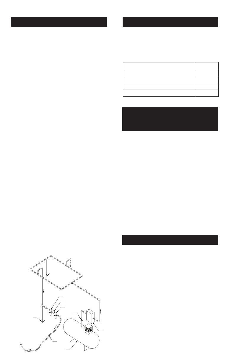
Figure 1
Closed Loop Pipe System
Sloped in the direction of air flow
Drain Leg
Ball Valve
To Tool Station
Filter
Drain Valve
Regulator
Lubricator
Ball
Valve
Ball Valve
Air Flow
Air Dryer
Air Compressor
and Tank
Air Hose
To Coupler
at or near Tool
Removing and Mounting
Disc and Buffing Pad to
Random Orbital Buffer
Buff pad
1. Disconnect air line from buffer.
2. Peel the old buff pad from the disc pad, by lifting an edge
and puling firmly upward.
3. Inspect the Hook material on the disc pad for damage or
debris clogging the hooks. Clean any debris or buffing
compound from the disc pad surface.
4. Attach a new buff pad to the disc pad, being careful to
center it as well as possible.
5. Apply hand pressure to engage the hooks and loops to
firmly seat the buff pad.
Disc pad
1. Disconnect air line from buffer.
2. Remove old disc pad from buffer by inserting the wrench,
supplied with the tool, between the rubber shroud and
the disc pad. Use the wrench to secure the buffer spindle
while turning the disc pad counter clockwise.
3. After the old disc pad has been removed from the buffer,
inspect the threaded hole in the spindle to ensure that the
threads are free of debris and undamaged.
4. Ensure that the phenolic washer is in place around the
threaded shaft of the new disc pad.
5. Secure the buffer spindle with the wrench and tighten the
new disc pad securely to the tool.
See 3M ASD Accessory catalog 61-5002-8098-9 and 61-
5002-8097-1 for additional Accessories.
WARNING!
An inadequately tightened disc pad could cause the
threaded shaft to break causing damage to the tool and work
piece and possible injury to the operator or bystanders.
Mounting rubber tool hanger accessory onto buffer
1. Disconnect air line from buffer;
2. Remove the existing two (2) M8 threaded plug and spacer
ring assemblies (items 27 and 28) with T-20 Torx driver*,
3. Using the M8 threaded plug and spacer ring assemblies
(items 27 and 28), secure the hanger onto the tool using
a T-20 Torx driver*.
*Note: if necessary a 2.5mm Allen wrench may be used in
place of a T-20 Torx driver
Adding Optional Side-Handle
1. Disconnect air line from buffer.
2. Remove the existing M8 threaded plug and spacer ring
assembly (items 27 and 28) from the desired side of the
buffer with a T-20 Torx driver*.
3. Screw the M8 threaded side handle into the tool. Tighten
securely by hand.
4. If the Side–Handle is used with the tool hanger, the Side–
Handle will directly replaces the existing M8 threaded plug
and spacer ring assembly (items 27 and 28).
Buff Pad Description Part Number
Finesse-it™ Bufng Pad, Orange Foam, 3
1
/4 in. 02648
Finesse-it™ Bufng Pad, Orange Foam, 3
3
/4 in, 02637
Finesse-it™ Bufng Pad, Grey Foam, 3
1
/4 in. 25134
Finesse-it™ Bufng Pad, Grey Foam, 3
3
/4 in, 25135
3M 3 in. Random Orbital Buffer 6 Revision 061009
Abrasive Systems Division
3M Center, Building 223-6N-02
St. Paul, MN 55144-1000
www.3M.com/abrasives
© 3M 2009
3M, Stikit and Hookit are trademarks of 3M Company.
34-8703-0160-2
Product Use: All statements, technical information and rec-
ommendations contained in this document are based up on
tests or experience that 3M believes are reliable. However,
many factors beyond 3M’s control can affect the use and
performance of a 3M product in a particular application,
including the conditions under which the 3M product is used
and the time and environmental conditions in which the prod-
uct is expected to perform. Since these factors are uniquely
within the user’s knowledge and control, it is essential that
the user evaluate the 3M product to determine whether it is
fit for a particular purpose and suitable for the user’s method
of application.
Warranty and Limited Remedy: 3M warrants this tool
against defects in workmanship and materials under normal
operating conditions for one (1) year from the date of pur
-
chase. 3M MAKES NO OTHER WARRANTIES, EXPRESS
OR IMPLIED, INCLUDING, BUT NOT LIMITED TO, ANY
IMPLIED WARRANTY OF MERCHANTABILITY OR FIT-
NESS FOR A PARTICULAR PURPOSE OR ANY IMPLIED
WARRANTY ARISING OUT OF A COURSE OF DEALING,
CUSTOM OR USAGE OF TRADE. User is responsible for
determining whether the 3M tool is fit for a particular pur-
pose and suitable for user’s application. User must operate
the tool in accordance with all applicable operating instruc-
tions, safety precautions, and other procedures stated in
the operating manual to be entitled to warranty coverage. 3M shall
have no obligation to repair or replace any tool or part that fails due
to normal wear, inadequate or improper maintenance, inadequate
cleaning, nonlubrication, improper operating environment, improper
utilities, operator error or misuse, alteration or modification, mishan-
dling, lack of reasonable care, or due to any accidental cause. If a
tool or any part thereof is defective within this warranty period, your
exclusive remedy and 3M’s sole obligation will be, at 3M’s option, to
repair or replace the tool or refund the purchase price.
Limitation of Liability: Except where prohibited by law, 3M and
seller will not be liable for any loss or damage arising from the 3M
product, whether direct, indirect, special, incidental or consequen-
tial, regardless of the legal theory asserted, including warranty,
contract, negligence or strict liability.
Submitting a Warranty Claim: Contact your dealer when
submitting a warranty claim in accordance with the restrictions
listed above. Please note that all warranty claims are subject to
manufacturer’s approval. Be sure to keep your sales receipt in a
safe place. This must be submitted when filing a warranty claim,
within 1 year from the date of purchase. For additional assistance
call 1-800-362-3550.
Product Repair after Warranty Has Expired: Repair of 3M Abra-
sive Power tools that are not under warranty is available through 3M
or a 3M Authorized Tool Repair Representative. Contact your 3M
Abrasive Power Tool Distributor for details, or call 1-800-362-3550.
3M 3 in. Random Orbital Buffer 9 Revision 061009
Liste des pièces
NUMÉRO
DU COM-
POSANT
NUMÉRO DE
PRODUIT 3M
CUP/NUMÉRO DE
PRODUIT 3M
DESCRIPTION QTÉ
1 A0040 28113 BAGUE DE RETENUE 1
2 A0021 28107 PALIER 1
3 30327 30327 PLAQUE DE FOND ARRIÈRE 1
4 A0042 28115 JOINT TORIQUE 1
5 30347 30347 ENSEMBLE DE CYLINDRE 1
6 B0005 28170 ROTOR 1
7 A0010 28099 AILETTE 5
8 A0041 28114 CLAVETTE WOODRUFF 1
9 30326 30326 PLAQUE DE FOND AVANT 1
10 A0019 28106 PALIER 1
11 A0045 28118 JOINT TORIQUE 1
12 30337 30337 RONDELLE ÉLASTIQUE – FILETAGE DE 50 MM 1
13 30361 30361 COMPENSATEUR D’ARBRE 1
14 A0122 28132 FILTRE 1
15 A0121 28131 CLAPET ANTI-RETOUR EN BEC DE CANARD 1
16 A0120 28130 BUTÉE DE SOUPAPE 1
17 A0090 28127 BAGUE DE RETENUE 1
18 A0938 28148 PALIER 1
19 A0016 28103 BAGUE D’ESPACEMENT 1
20 A0017 28104 RONDELLE BELLEVILLE 1
21 B0312 28183 MANDRIN 1
22 A0146 28134 CLÉ ANGLAISE POUR TAMPON de 17 mm 1
23 A0018 28105 BAGUE DE RETENUE 1
24 20350 20350 Tampon pour disques de ponçage propre Hookit™ 3M™ – 3 po x ½ po x ¼ po – 20 ext. 1
25 Divers Divers Tampon à lustrer en mousse Finesse-it™ (diamètre de 3,25 po ou de 3,75 po) 1
26 30331 30331 ANNEAU DE SUSPENSION 1
27 30332 30332 BOUCHON FILETÉ M8 2
28 30328 30328 BAGUE D’ESPACEMENT 2
29 30362 30362 COIFFE 1
30 30359 30359 BOÎTIER DU MOTEUR 1
31 30300 30300 TIGE À RESSORT 1
32 A0015 28102 MANCHON DE SOUPAPE 1
33 30338 30338 ENSEMBLE TIGE DE SOUPAPE 1
34 A0043 28116 JOINT TORIQUE 1
35 30348 30348 RÉGULATEUR DE VITESSE DE POLISSAGE 1
36 A0039 28112 BAGUE DE RETENUE 1
37 30334 30334 POIGNÉE LATÉRALE OPT
38 30336 30336 JOINT D’ÉTANCHÉITÉ 1
39 30357 30357 BUSE D’ÉCHAPPEMENT DU MOTEUR 1
40 30314 30314 VIS 3
41 30344 30344 JOINT TORIQUE 1
42 A0009 28098 SIÈGE DE SOUPAPE 1
43 A0007 28096 SOUPAPE 1
44 A0014 28101 RESSORT DE SOUPAPE 1
45 30315 30315 ENSEMBLE D’ÉTANCHÉITÉ DU TUYAU D’AIR COMPRIMÉ 1
46 30333 30333 TUYAU D’ADMISSION 1
47 30308 30308 VIS 4
48 30301 30301 DOUILLE FILETÉE 4
49 30364 30364 POIGNÉE 1
50 30365 30365 POIGNÉE 1
51 30342 30342 LEVIER DE COMMANDE 1
52 30339 30339 SILENCIEUX 1
53 30346 30346 SILENCIEUX 1
54 30343 30343 JOINT TORIQUE 1
55 30360 30360 COUVERCLE D’ÉCHAPPEMENT 1
56 30329 30329 CAPUCHON D’EXTRÉMITÉ D’ADMISSION/D’ÉCHAPPEMENT 1
57 30306 30306 BAGUE IMPERDABLE D’ENTRÉE 1
58 30305 30305 JOINT TORIQUE 1
59 30321 30321 VIS 2
60 A0013 28100 DOUILLE D’ENTRÉE À FILETAGE 1/4-18 NPT 1
3M 3 in. Random Orbital Buffer 15 Revision 061009
Lista de Piezas
NÚMERO DE
ARTÍCULO
3M PM 3M UPC PN DESCRIPCIÓN CANTIDAD
1 A0040 28113 RETÉN 1
2 A0021 28107 COJINETE 1
3 30327 30327 PLACA TERMINAL TRASERA 1
4 A0042 28115 O-RING 1
5 30347 30347 CONJUNTO DE CILINDRO 1
6 B0005 28170 ROTOR 1
7 A0010 28099 PALETA 5
8 A0041 28114 CHAVETA WOODRUFF 1
9 30326 30326 PLACA TERMINAL DELANTERA 1
10 A0019 28106 COJINETE 1
11 A0045 28118 O-RING 1
12 30337 30337 ANILLO DE SEGURIDAD – ROSCA DE 50 MM 1
13 30361 30361 BALANCEADOR DEL EJE 1
14 A0122 28132 FILTRO 1
15 A0121 28131 VÁLVULA DE RETENCIÓN DE BOCA PLANA 1
16 A0120 28130 RETÉN DE VÁLVULA 1
17 A0090 28127 RETÉN 1
18 A0938 28148 COJINETE 1
19 A0016 28103 SEPARADOR 1
20 A0017 28104 ARANDELA BELEVILLE 1
21 B0312 28183 HUSILLO 1
22 A0146 28134 LLAVE DE TUERCAS PARA ALMOHADILLA DE 17 mm 1
23 A0018 28105 RETÉN 1
24 20350 20350
Almohadilla para Disco de Lijado Limpio Hookit™ de 3M™ - 3 pulg. x 1/2
pulg. x 1/4-20 Ext.
1
25 Diversos Diversos
Almohadilla de Espuma de Goma para Pulimentar Finesse-it™ (3,25
pulg. ó 3,75 pulg. de diámetro)
1
26 30331 30331 GANCHO PARA COLGARLA 1
27 30332 30332 TAPÓN ROSCADO M8 2
28 30328 30328 ANILLO ESPACIADOR 2
29 30362 30362 CUBIERTA 1
30 30359 30359 CARCASA DEL MOTOR 1
31 30300 30300 PASADOR DE RESORTE 1
32 A0015 28102 CAMISA DE VÁLVULA 1
33 30338 30338 CONJUNTO DE VÁSTAGO DE VÁLVULA 1
34 A0043 28116 O-RING 1
35 30348 30348 CONTROL DE LA VELOCIDAD PROTEGIDO 1
36 A0039 28112 RETÉN 1
37 30334 30334 EMPUÑADURA LATERAL OPC
38 30336 30336 JUNTA 1
39 30357 30357 TOBERA DE ESCAPE DEL MOTOR 1
40 30314 30314 TORNILLO 3
41 30344 30344 O-RING 1
42 A0009 28098 ASIENTO DE VÁLVULA 1
43 A0007 28096 VÁLVULA 1
44 A0014 28101 RESORTE DE VÁLVULA 1
45 30315 30315 CONJUNTO DE SELLOS PARA TUBERÍAS NEUMÁTICAS 1
46 30333 30333 TUBERÍA DE ENTRADA 1
47 30308 30308 TORNILLO 4
48 30301 30301 INSERTO ROSCADO 4
49 30364 30364 EMPUÑADURA 1
50 30365 30365 MANGO 1
51 30342 30342 PALANCA DE ADMISIÓN DE GASES 1
52 30339 30339 SILENCIADOR 1
53 30346 30346 SILENCIADOR 1
54 30343 30343 O-RING 1
55 30360 30360 TAPA DE ESCAPE 1
56 30329 30329 CÁPSULA DE ENTRADA/SALIDA 1
57 30306 30306 ANILLO DE ENTRADA IMPERDIBLE 1
58 30305 30305 O-RING 1
59 30321 30321 TORNILLO 2
60 A0013 28100 CONJUNTO DE BUJE DE ENTRADA, ROSCA DE 1/4-18 NPT 1
3M 3 in. Random Orbital Buffer 21 Revision 061009
NÚMERO DO
ITEM
3M PN 3M UPC PN DESCRIÇÃO QTY
1 A0040 28113 ANEL DE RETENÇÃO 1
2 A0021 28107 MANCAL 1
3 30327 30327 PLACA FINAL TRASEIRA 1
4 A0042 28115 ANEL TIPO “O” 1
5 30347 30347 CONJUNTO DO CILINDRO 1
6 B0005 28170 ROTOR 1
7 A0010 28099 PALHETA 5
8 A0041 28114 CHAVETA EM MEIA-LUA 1
9 30326 30326 PLACA FINAL FRONTAL 1
10 A0019 28106 MANCAL 1
11 A0045 28118 ANEL TIPO “O” 1
12 30337 30337 ANEL DE TRAVAMENTO - CHANFRO DE 50 MM 1
13 30361 30361 BALANCEADOR DE EIXO 1
14 A0122 28132 FILTRO 1
15 A0121 28131 VÁLVULA DE CHECAGEM DE BICO DE PATO 1
16 A0120 28130 RETENTOR DA VÁLVULA 1
17 A0090 28127 ANEL DE RETENÇÃO 1
18 A0938 28148 MANCAL 1
19 A0016 28103 ESPAÇADOR 1
20 A0017 28104 ARRUELA BELLEVILLE 1
21 B0312 28183 FUSO 1
22 A0146 28134 CHAVE DE BOINA DE 17 mm 1
23 A0018 28105 ANEL DE RETENÇÃO 1
24 20350 20350 Boina para disco de lixagem limpa Hookit” da 3M™ - Ext. 3 pol x 1/2 pol x 1/4-20 1
25 Diversos Diversos Boina de polimento de espuma Finesse-it™ (Diâmetro de 3.25 pol ou 3.75 pol) 1
26 30331 30331 ALÇA 1
27 30332 30332 PLUGUE CHANFRADO M8 2
28 30328 30328 ANEL ESPAÇADOR 2
29 30362 30362 ENVOLTÓRIO 1
30 30359 30359 ALOJAMENTO DO MOTOR 1
31 30300 30300 PINO DA MOLA 1
32 A0015 28102 LUVA DE VÁLVULA 1
33 30338 30338 CONJUNTO DA HASTE DA VÁLVULA 1
34 ANEL “O” 28116 ANEL TIPO “O” 1
35 30348 30348 CONTROLE DE VELOCIDADE DE JATO 1
36 A0039 28112 ANEL DE RETENÇÃO 1
37 30334 30334 ALÇA LATERAL OPC
38 30336 30336 JUNTA 1
39 30357 30357 BICO DE DESCARGA DO MOTOR 1
40 30314 30314 PARAFUSO 3
41 30344 30344 ANEL TIPO “O” 1
42 A0009 28098 BASE DE VÁLVULA 1
43 A0007 28096 VÁLVULA 1
44 A0014 28101 MOLA DE VÁLVULA 1
45 30315 30315 CONJUNTO DE VEDAÇÃO DA LINHA DE AR 1
46 30333 30333 TUBULAÇÃO DE ENTRADA 1
47 30308 30308 PARAFUSO 4
48 30301 30301 BUCHA CHANFRADA 4
49 30364 30364 ALÇA 1
50 30365 30365 CABO 1
51 30342 30342 ALAVANCA DO REGULADOR 1
52 30339 30339 ABAFADOR 1
53 30346 30346 ABAFADOR 1
54 30343 30343 ANEL TIPO “O” 1
55 30360 30360 COBERTURA DA DESCARGA 1
56 30329 30329 COBERTURA FINAL DA ENTRADA/DESCARGA 1
57 30306 30306 ANEL CATIVO DA ENTRADA 1
58 30305 30305 ANEL TIPO “O” 1
59 30321 30321 PARAFUSO 2
60 A0013 28100 CONJUNTO DO BUCHAMENTO DA ENTRADA NPT 1/4-18 1
LISTA DE PEÇAS
3M 3 in. Random Orbital Buffer 28 Revision 061009
产品配置/规格:11,000 RPM随机轨道磨光器
* 标称噪音水平;根据EN ISO 15744:2002标准执行测定。.
**申报振动水平符合EN12096 ;测量进行按照标准的ISO 8662-8:1997除了饲料武力减少到10N + / - 5N由于不切实际的经营这个小工具30N + /
- 5N中所说的标准。
重要注意事项:表中所规定的噪音和振动数值均来自实验室测试,符合规定的条款和标准,而且并未完全评估所有情况的风险。 实际暴
露数值和个人遭受风险或伤害的程度因情境不同而各异,并且取决于周围的环境,个人工作、加工特定材料、工作站设计的方式,以及暴
露时间和用户的身体状况。 如果使用的是标称数值而不是就任何个人风险进行评定的实际暴露数值,那么3M概不负责这些后果。
t.
操作/养护说明
PRIOR TO THE OPERATION
The tool is intended to be operated as a hand held tool. It is always recommended that while using the tool, operators stand on a solid floor, in a secure posi-
tion with a firm grip and footing. Be aware that the sander can develop a torque reaction. See the section “SAFETY PRECAUTIONS”.
Use a clean lubricated air supply that will give a measured air pressure at the tool of 6.2 bar (90 psig) when the tool is running with the lever fully depressed.
It is recom¬mended to use an approved 10 mm (3/8 in) x 8 m (25 ft) maximum length airline. Connect the tool to the air supply as shown in Figure 1. Do
not connect the tool to the airline system without an easily accessible air shut off valve. It is strongly recommended that an air filter, regulator and lubricator
(FRL) be used as shown in Figure 1as this will supply clean, lubricated air at the correct pressure to the tool. In any case appropriate air pressure regulators
shall be used at all times while operating this tool where the supply pressure exceeds the marked maximum of the tool. Details of such equipment can be
obtained for your tool distributor. If such equipment is not used, the tool should be manually lubricated. To manually lubricate the tool, disconnect the
airline and put 2 to 3 drops of suitable pneumatic motor lubricating oil such as 3MTM Air Tool Lubricant PN 20451, Fuji Kosan FK-20, Mobil ALMO 525
into the hose end (inlet) of the tool. Reconnect tool to the air supply and run tool slowly for a few seconds to allow air to circulate the oil. If the tool is used
frequently, lubricate it on a daily basis or lubricate it if the tool starts to slow or lose power. It is recommended that the air pressure at the tool be 6.2 bar (90
psig) while the tool is running so the maximum RPM is not exceeded. The tool can be run at lower pressures but should never be run higher than 6.2 bar (90
psig). If run at lower pressure the performance of the tool is reduced
型号 轨道
砂碟尺
毫米
(英寸)
磨光垫
编号
产品净重
公斤(
磅)
高度
毫米(英
寸)
长度
毫米(英
寸)
*噪音水平
dBA 压力
(强力型)
*噪音水平
dBA 压力
(强力型)
**不确定度
K m/s
2
28333
12 mm
(
15
/32 in.)
77 (3) 20350 0.82 (1.8)
99.6
(3.92)
233.2
(9.18)
78 (87) 3.8 (12.5) 0.539
建议进气管之
尺寸 ━ 最小
10mm 3/8in
建议进气管之
长度 ━ 最大
8 公尺 25 英呎
气压
最大工作气压 6.2bar 90psig
建议之最小值 不适用 不适用
3M 3 in. Random Orbital Buffer 30 Revision 061009
EC符合规定声明
制造商名称:
製造商地址:
3M公司,研磨系統部
3M Center, Building 223-6N-02
St. Paul, MN USA 55144.
谨在此宣称以下所述之机器符合机械指令2006/42/EC以及截至目前所有修订适用且必要的卫生及安全要求。
说明:
3M™ 磨光器,76毫米(3英寸) x 12 毫米(15/32英寸)轨道直径
型号: 28333
本机械参照或符合下列相关标准之全部或部分内容:
EN ISO 12100-1:2003 机械安全性。基本概念,设计一般原则–
EN ISO 12100-2:2003 基本术语及技术原则
EN 792-8:2001 手持式非电动工具 ━ 安全规定 ━ 第8部分:砂光机及抛光机
EN 983:1996 机械安全性。安全规定 ━液压能力系统与部件 ━ 气动
EN ISO 14121-1:2007 机械安全性。风险评估原则
EN ISO 8662-8:1997* 手持可携式动力工具 ━ 把手上的振动测量 ━ 第8部分:抛光机及回转式、圆轨道
及偏心圆轨道砂光机。
EN ISO 28662-1:1992 手持可携式动力工具 ━ 把手上的振动测量 ━ 第1部分:一般
EN ISO 15744:2002 手持式非电动工具。噪音测量法规。工程方法(等级2)
*减小进给力 - 请查阅产品规格
Product Use: All statements, technical information and rec-
ommendations contained in this document are based up on
tests or experience that 3M believes are reliable. However,
many factors beyond 3M’s control can affect the use and
performance of a 3M product in a particular application,
including the conditions under which the 3M product is used
and the time and environmental conditions in which the prod-
uct is expected to perform. Since these factors are uniquely
within the user’s knowledge and control, it is essential that
the user evaluate the 3M product to determine whether it is
fit for a particular purpose and suitable for the user’s method
of application.
Warranty and Limited Remedy: 3M warrants this tool
against defects in workmanship and materials under normal
operating conditions for one (1) year from the date of pur
-
chase. 3M MAKES NO OTHER WARRANTIES, EXPRESS
OR IMPLIED, INCLUDING, BUT NOT LIMITED TO, ANY
IMPLIED WARRANTY OF MERCHANTABILITY OR FIT-
NESS FOR A PARTICULAR PURPOSE OR ANY IMPLIED
WARRANTY ARISING OUT OF A COURSE OF DEALING,
CUSTOM OR USAGE OF TRADE. User is responsible for
determining whether the 3M tool is fit for a particular pur-
pose and suitable for user’s application. User must operate
the tool in accordance with all applicable operating instruc-
tions, safety precautions, and other procedures stated in
the operating manual to be entitled to warranty coverage. 3M shall
have no obligation to repair or replace any tool or part that fails due
to normal wear, inadequate or improper maintenance, inadequate
cleaning, nonlubrication, improper operating environment, improper
utilities, operator error or misuse, alteration or modification, mishan-
dling, lack of reasonable care, or due to any accidental cause. If a
tool or any part thereof is defective within this warranty period, your
exclusive remedy and 3M’s sole obligation will be, at 3M’s option, to
repair or replace the tool or refund the purchase price.
Limitation of Liability: Except where prohibited by law, 3M and
seller will not be liable for any loss or damage arising from the 3M
product, whether direct, indirect, special, incidental or consequen-
tial, regardless of the legal theory asserted, including warranty,
contract, negligence or strict liability.
Submitting a Warranty Claim: Contact your dealer when
submitting a warranty claim in accordance with the restrictions
listed above. Please note that all warranty claims are subject to
manufacturer’s approval. Be sure to keep your sales receipt in a
safe place. This must be submitted when filing a warranty claim,
within 1 year from the date of purchase. For additional assistance
call 1-800-362-3550.
Product Repair after Warranty Has Expired: Repair of 3M Abra-
sive Power tools that are not under warranty is available through 3M
or a 3M Authorized Tool Repair Representative. Contact your 3M
Abrasive Power Tool Distributor for details, or call 1-800-362-3550.
磨料系统部门
3M Center, Building 223-6N-02
St. Paul, MN 55144-1000
www.3M.com/abrasives
© 3M 2009
3M, Stikit, 和 Hookit 是3M 公司的商
34-8703-0160-2
3M 3 in. Random Orbital Buffer 31 Revision 061009
3M 3 in. Random Orbital Buffer 32 Revision 061009
1 / 1

3M Buffers Operating instructions

Category
Power tools
Type
Operating instructions
This manual is also suitable for

Ask a question and I''ll find the answer in the document

Finding information in a document is now easier with AI

Ask the document