
GB
Circular Saw Instruction Manual
F
Scie circulaire
Manuel d’instructions
D
Handkreissäge Betriebsanleitung
I
Sega circolare Istruzioni per l’uso
NL
Cirkelzaagmachine Gebruiksaanwijzing
E
Sierra circular Manual de instrucciones
P
Serra circular Manual de instruções
DK
Rundsav Brugsanvisning
GR ∆ισκπρίν δηγίες ρήσεως
5603R
5703R
5705R
5903R
5103R
5143R
Page is loading ...
Page is loading ...
Page is loading ...

5
ENGLISH (Original instructions)
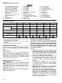
Explanation of general view
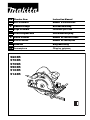
1 A typical illustration of proper
hand support, workpiece sup-
port, and supply cord routing (if
applicable).
2 To avoid kickback, do support
board or panel near the cut.
3 Do not support board or panel
away from the cut.
4Lever
5 Clamping screw
6 Base plate
7 Top guide
8Base
9 60° angle cuts
10 45° angle cuts
11 30° angle cuts
12 Straight cuts
13 Blade
14 Setting protuberances
15 Hex socket head bolt
(For adjusting riving knife)
16 Cutting depth
17 Lock-off button
18 Switch trigger
19 Hex wrench
20 Shaft lock
21 Hex socket head bolt
22 Outer flange
23 Saw blade
24 Inner flange
25 Vacuum cleaner
26 Limit mark
27 Screwdriver
28 Brush holder cap
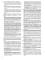
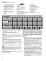
SPECIFICATIONS
• Due to our continuing program of research and devel-
opment, the specifications herein are subject to change
without notice.
• Specifications may differ from country to country.
• Weight according to EPTA-Procedure 01/2003
Intended use
The tool is intended for performing lengthways and
crossways straight cuts and mitre cuts with angles in
wood while in firm contact with the workpiece.
Power supply
The tool should be connected only to a power supply of
the same voltage as indicated on the nameplate, and can
only be operated on single-phase AC supply. They are
double-insulated in accordance with European Standard
and can, therefore, also be used from sockets without
earth wire.
GEA010-1
General Power Tool Safety Warnings
WARNING Read all safety warnings and all
instructions. Failure to follow the warnings and
instructions may result in electric shock, fire and/or
serious injury.
Save all warnings and instructions for future refer-
ence.
GEB029-1
SPECIFIC SAFETY RULES
DO NOT let comfort or familiarity with product
(gained from repeated use) replace strict adherence
to circular saw safety rules. If you use this tool
unsafely or incorrectly, you can suffer serious per-
sonal injury.
Danger:
1. Keep hands away from cutting area and the
blade. Keep your second hand on auxiliary han-
dle, or motor housing. If both hands are holding
the saw, they cannot be cut by the blade.
2. Do not reach underneath the workpiece. The
guard cannot protect you from the blade below the
workpiece. Do not attempt to remove cut material
when blade is moving.
CAUTION: Blades coast after turn off. Wait until
blade stops before grasping cut material.
3. Adjust the cutting depth to the thickness of the
workpiece. Less than a full tooth of the blade teeth
should be visible below the workpiece.
4. Never hold piece being cut in your hands or
across your leg. Secure the workpiece to stable
platform. It is important to support the work properly
to minimize body exposure, blade binding, or loss of
control. (Fig. 1)
5. Hold power tool by insulated gripping surfaces
when performing an operation where the cutting
tool may contact hidden wiring or its own cord.
Contact with a “live” wire will also make exposed
metal parts of the power tool “live” and shock the
operator.
6. When ripping always use a rip fence or straight
edge guide. This improves the accuracy cut and
reduces the chance of blade binding.
7. Always use blades with correct size and shape
(diamond versus round) of arbour holes. Blades
that do not match the mounting hardware of the saw
will run eccentrically, causing loss of control.
8. Never use damaged or incorrect blade washers
or bolt. The blade washers and bolt were specially
designed for your saw, for optimum performance and
safety of operation.
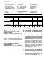
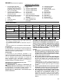
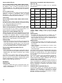
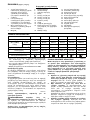
Model 5603R 5703R 5705R 5903R 5103R 5143R
Blade diameter 165 mm 190 mm 190 mm 235 mm 270 mm 355 mm
Max.
cutting depth
at 90° 54 mm 66 mm 66 mm 85 mm 100 mm 130 mm
at 45° 38 mm 46 mm 46 mm 64 mm 73 mm 90 mm
No load speed (min
-1
) 5,000 4,800 4,800 4,500 3,800 2,700
Overall length 330 mm 356 mm 356 mm 400 mm 442 mm 607 mm
Net weight 4.9 kg 5.7 kg 5.7 kg 7.2 kg 9.4 kg 14.0 kg
Safety class /II /II /II /II /II /II

6
9. Causes and Operator Prevention of Kickback:
– kickback is a sudden reaction to a pinched, bound
or misaligned saw blade, causing an uncontrolled
saw to lift up and out of the workpiece toward the
operator;
– when the blade is pinched or bound tightly by the
kerf closing down, the blade stalls and the motor
reaction drives the unit rapidly back toward the
operator;
– if the blade becomes twisted or misaligned in the
cut, the teeth at the back edge of the blade can dig
into the top surface of the wood causing the blade
to climb out of the kerf and jump back toward the
operator.
Kickback is the result of saw misuse and/or incorrect
operating procedures or conditions and can be
avoided by taking proper precautions as given
below.
• Maintain a firm grip with both hands on the
saw and position your arms to resist kickback
forces. Position your body to either side of the
blade, but not in line with the blade. Kickback
could cause the saw to jump backwards, but kick-
back forces can be controlled by the operator, if
proper precautions are taken.
•
When blade is binding, or when interrupting a
cut for any reason, release the trigger and hold
the saw motionless in the material until the
blade comes to a complete stop. Never attempt
to remove the saw from the work or pull the saw
backward while the blade is in motion or kick-
back may occur.
Investigate and take corrective
actions to eliminate the cause of blade binding.
• When restarting a saw in the workpiece, centre
the saw blade in the kerf and check that saw
teeth are not engaged into the material. If saw
blade is binding, it may walk up or kickback from
the workpiece as the saw is restarted.
• Support large panels to minimise the risk of
blade pinching and kickback. Large panels tend
to sag under their own weight. Supports must be
placed under the panel on both sides, near the line
of cut and near the edge of the panel.
To minimize the risk of blade pinching and kickback.
When cutting operation requires the resting of the
saw on the workpiece, the saw should be rested on
the larger portion and the smaller piece cut off. (Fig.
2 & 3)
• Do not use dull or damaged blades. Unsharp-
ened or improperly set blades produce narrow kerf
causing excessive friction, blade binding and kick-
back. Keep blade sharp and clean. Gum and wood
pitch hardened on blades slows saw and
increases potential for kickback. Keep blade clean
by first removing it from tool, then cleaning it with
gum and pitch remover, hot water or kerosene.
Never use gasoline.
• Blade depth and bevel adjusting locking levers
must be tight and secure before making cut. If
blade adjustment shifts while cutting, it may cause
binding and kickback.
• Use extra caution when making a “plunge cut”
into existing walls or other blind areas. The
protruding blade may cut objects that can cause
kickback. For plunge cuts, retract lower guard
using retracting handle.
• ALWAYS hold the tool firmly with both hands.
NEVER place your hand or fingers behind the
saw. If kickback occurs, the saw could easily jump
backwards over your hand, leading to serious per-
sonal injury. (Fig. 4)
• Never force the saw. Forcing the saw can
cause uneven cuts, loss of accuracy, and pos-
sible kickback. Push the saw forward at a speed
so that the blade cuts without slowing.
10. Check lower guard for proper closing before
each use. Do not operate the saw if lower guard
does not move freely and close instantly. Never
clamp or tie the lower guard into the open posi-
tion. If saw is accidentally dropped, lower guard may
be bent. Raise the lower guard with the retracting
handle and make sure it moves freely and does not
touch the blade or any other part, in all angles and
depths of cut. To check lower guard, open lower
guard by hand, then release and watch guard clo-
sure. Also check to see that retracting handle does
not touch tool housing. Leaving blade exposed is
VERY DANGEROUS and can lead to serious per-
sonal injury.
11. Check the operation of the lower guard spring. If
the guard and the spring are not operating prop-
erly, they must be serviced before use. Lower
guard may operate sluggishly due to damaged
parts, gummy deposits, or a build-up of debris.
12. Lower guard should be retracted manually only
for special cuts such as “plunge cuts” and
“compound cuts.” Raise lower guard by retract-
ing handle and as soon as blade enters the
material, the lower guard must be released. For
all other sawing, the lower guard should operate
automatically.
13. Always observe that the lower guard is covering
the blade before placing saw down on bench or
floor. An unprotected, coasting blade will cause the
saw to walk backwards, cutting whatever is in its
path. Be aware of the time it takes for the blade to
stop after switch is released. Before setting the tool
down after completing a cut, be sure that the lower
guard has closed and the blade has come to a com-
plete stop.
14. Use the appropriate riving knife for the blade
being used. For the riving knife to work, it must be
thicker than the body of the blade but thinner than
the tooth set of the blade.
15. Adjust the riving knife as described in this
instruction manual. Incorrect spacing, positioning
and alignment can make the riving knife ineffective
in preventing kickback.
16. Always use the riving knife except when plunge
cutting. Riving knife must be replaced after plunge
cutting. Riving knife causes interference during
plunge cutting and can create kickback.
17. For the riving knife to work, it must be engaged
in the workpiece. The riving knife is ineffective in
preventing kickback during short cuts.
18. Do not operate the saw if riving knife is bent.
Even a light interference can slow the closing rate of
a guard.
19. Use extra caution when cutting damp wood,
pressure treated lumber, or wood containing
knots. Adjust speed of cut to maintain smooth
advancement of tool without decrease in blade
speed.

7
20. Avoid Cutting Nails. Inspect for and remove all
nails from lumber before cutting.
21. Place the wider portion of the saw base on that
part of the workpiece which is solidly supported,
not on the section that will fall off when the cut is
made. As examples, Fig. 5 illustrates the RIGHT
way to cut off the end of a board, and Fig. 6 the
WRONG way. If the workpiece is short or small,
clamp it down. DO NOT TRY TO HOLD SHORT
PIECES BY HAND! (Fig. 5 & 6)
22. Never attempt to saw with the circular saw held
upside down in a vise. This is extremely danger-
ous and can lead to serious accidents. (Fig. 7)
23. Some material contains chemicals which may be
toxic. Take caution to prevent dust inhalation
and skin contact. Follow material supplier safety
data.
24. Do not stop the blades by lateral pressure on the
saw blade.
25. Always use blades recommended in this manual.
Do not use any abrasive wheels.
26. Wear a dust mask and hearing protection when
use the tool.
SAVE THESE INSTRUCTIONS.
WARNING:
MISUSE or failure to follow the safety rules stated in
this instruction manual may cause serious personal
injury.
FUNCTIONAL DESCRIPTION
CAUTION:
• Always be sure that the tool is switched off and
unplugged before adjusting or checking function on the
tool.
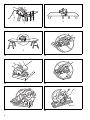
Adjusting depth of cut (Fig. 8)
CAUTION:
• After adjusting the depth of cut, always tighten the lever
securely.
Loosen the lever on the depth guide and move the base
up or down. At the desired depth of cut, secure the base
by tightening the lever.
For cleaner, safer cuts, set cut depth so that no more
than one blade tooth projects below workpiece. Using
proper cut depth helps to reduce potential for dangerous
KICKBACKS which can cause personal injury.
Bevel cutting (Fig. 9)
For model 5603R, 5703R, 5705R, 5903R, 5103R
Loosen the clamping screws in front and back, and tilt the
tool to the desired angle for bevel cuts (0° – 45°). Secure
the clamping screws tightly in front and back after making
the adjustment.
For model 5143R
Loosen the clamping screw in front and tilt the tool to the
desired angle for bevel cuts (0° – 60°). Secure the
clamping screw tightly in front after making the
adjustment.
Sighting
For model 5603R, 5703R, 5705R, 5903R, 5103R
(Fig. 10 & 11)
For straight cuts, align the A position on the front of the
base with your cutting line. For 45° bevel cuts, align the B
position with it.
For model 5143R (Fig. 12)
Align your sight line with either the 0° notch for straight
cutting or the 30° notch for 30° angle cuts or the 45°
notch for 45° angle cuts or the 60° notch for 60° angle
cuts.
Riving knife adjustment (Fig. 13)
Use the hex wrench to loosen the hex socket head bolt
for the riving knife adjustment, then raise the safety
cover. Move the riving knife up or down over the two pro-
truberances for settings indicated in the illustration, so as
to obtain the proper clearance between the riving knife
and saw blade.
CAUTION:
• Ensure that the riving knife is adjusted such that:
The distance between the riving knife and the toothed
rim of the saw blade is not more than 5 mm. The
toothed rim does not extend more than 5 mm beyond
the lower edge of the riving knife.
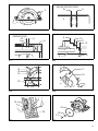
Switch action (Fig. 14)
CAUTION:
• Before plugging in the tool, always check to see that
the switch trigger actuates properly and returns to the
“OFF” position when released.
To prevent the switch trigger from being accidentally
pulled, a lock-off button is provided. To start the tool,
push in the lock-off button and pull the switch trigger.
Release the switch trigger to stop.
ASSEMBLY
CAUTION:
• Always be sure that the tool is switched off and
unplugged before carrying out any work on the tool.
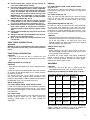
Removing or installing saw blade (Fig. 15 & 16)
The following blade can be used with this tool.
The thickness of the riving knife is 1.8 mm for Models
5603R, 5703R and 5705R or 2.0 mm for Models for
5903R and 5103R or 2.5 mm for Model 5143R.
Model Max. dia. Min. dia.
Blade
thickness
Kerf
5603R 165 mm 150 mm
1.6 mm
or less
1.9 mm
or more
5703R 190 mm 170 mm
1.6 mm
or less
1.9 mm
or more
5705R 190 mm 170 mm
1.6 mm
or less
1.9 mm
or more
5903R 235 mm 210 mm
1.7 mm
or less
2.1 mm
or more
5103R 270 mm 260 mm
1,8 mm
or less
2,2 mm
or more
5143R 355 mm 350 mm
2,3 mm
or less
2,7 mm
or more

8
CAUTION:
• Do not use saw blades which do not comply with the
characteristics specified in these instructions.
• Do not use saw blades the disc of which is thicker or
the set of which is smaller than the thickness of the riv-
ing knife.
CAUTION:
• Be sure the blade is installed with teeth pointing up at
the front of the tool.
• Use only the Makita wrench to install or remove the
blade.
• Never depress the shaft lock while the saw is running.
To remove the blade, press the shaft lock so that the
blade cannot revolve and use the hex wrench to loosen
the hex bolt counterclockwise. Then remove the hex bolt,
outer flange and blade.
To install the blade, follow the removal procedure in
reverse. BE SURE TO TIGHTEN THE HEX BOLT
CLOCKWISE SECURELY.
When changing blade, make sure to also clean upper
and lower blade guards of accumulated sawdust. Such
efforts do not, however, replace the need to check lower
guard operation before each use.
Connecting a vacuum cleaner (Fig.17)
When you wish to perform clean cutting operation, con-
nect a Makita vacuum cleaner to your tool. Install the joint
on the tool using the screws. Then connect a hose of the
vacuum cleaner to the joint as shown in the figure.
Operation (Fig. 18)
CAUTION:
• Be sure to move the tool forward in a straight line
gently. Forcing or twisting the tool will result in
overheating the motor and dangerous kickback,
possibly causing severe injury.
Hold the tool firmly. The tool is provided with both a front
grip and rear handle. Use both to best grasp the tool. If
both hands are holding saw, they cannot be cut by the
blade. Set the base on the workpiece to be cut without
the blade making any contact. Then turn the tool on and
wait until the blade attains full speed. Now simply move
the tool forward over the workpiece surface, keeping it
flat and advancing smoothly until the sawing is
completed.
To get clean cuts, keep your sawing line straight and your
speed of advance uniform. If the cut fails to properly fol-
low your intended cut line, do not attempt to turn or force
the tool back to the cut line. Doing so may bind the blade
and lead to dangerous kickback and possible serious
injury. Release switch, wait for blade to stop and then
withdraw tool. Realign tool on a new cut line, and start
cut again. Attempt to avoid positioning which exposes
operator to chips and wood dust being ejected from saw.
Use eye protection to help avoid injury.
CAUTION:
• The riving knife should always be used except when
plunging in the middle of the workpiece.
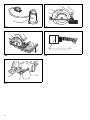
Rip fence (Guide rule) (Fig. 19)
The handy rip fence allows you to do extra-accurate
straight cuts. Simply slide the rip fence up snugly against
the side of the workpiece and secure it in position with
the screw on the front of the base. It also makes
repeated cuts of uniform width possible.
MAINTENANCE
CAUTION:
• Always be sure that the tool is switched off and
unplugged before attempting to perform inspection or
maintenance.
Replacing carbon brushes (Fig. 20 & 21)
Remove and check the carbon brushes regularly.
Replace when they wear down to the limit mark. Keep
the carbon brushes clean and free to slip in the holders.
Both carbon brushes should be replaced at the same
time. Use only identical carbon brushes.
Use a screwdriver to remove the brush holder caps. Take
out the worn carbon brushes, insert the new ones and
secure the brush holder caps.
To maintain product SAFETY and RELIABILITY, repairs,
any other maintenance or adjustment should be
performed by Makita Authorized Service Centers, always
using Makita replacement parts.
ACCESSORIES
CAUTION:
• These accessories or attachments are recommended
for use with your Makita tool specified in this manual.
The use of any other accessories or attachments might
present a risk of injury to persons. Only use accessory
or attachment for its stated purpose.
If you need any assistance for more details regarding
these accessories, ask your local Makita service center.
• Saw blades
• Rip fence (Guide rule)
• Hex wrench
• Joint
ENG102-2
For European countries only
Noise
The typical A-weighted noise level determined according
to EN60745:
For Model 5603R
Sound pressure level (L
pA
): 93 dB (A)
Sound power level (L
wA
): 104 dB (A)
Uncertainty (K): 3 dB (A)
For Model 5703R
Sound pressure level (L
pA
): 93 dB (A)
Sound power level (L
wA
): 104 dB (A)
Uncertainty (K): 3 dB (A)
For Model 5705R
Sound pressure level (L
pA
): 94 dB (A)
Sound power level (L
wA
): 105 dB (A)
Uncertainty (K): 3 dB (A)
For Model 5903R
Sound pressure level (L
pA
): 95 dB (A)
Sound power level (L
wA
): 106 dB (A)
Uncertainty (K): 3 dB (A)
For Model 5103R
Sound pressure level (L
pA
): 97 dB (A)
Sound power level (L
wA
): 108 dB (A)
Uncertainty (K): 3 dB (A)
For Model 5143R
Sound pressure level (L
pA
): 94 dB (A)
Sound power level (L
wA
): 105 dB (A)
Uncertainty (K): 3 dB (A)
Wear ear protection.

9
Vibration
The vibration total value (tri-axial vector sum) determined
according to EN60745:
ENG214-2
For Model 5603R
Work mode: cutting chipboard
Vibration emission (a
h
): 2.5 m/s
2
or less
Uncertainty (K): 1.5 m/s
2
ENG213-1
For Model 5703R
Work mode: cutting chipboard
Vibration emission (a
h
): 3.5 m/s
2
Uncertainty (K): 1.5 m/s
2
ENG214-2
For Model 5705R
Work mode: cutting chipboard
Vibration emission (a
h
): 2.5 m/s
2
or less
Uncertainty (K): 1.5 m/s
2
ENG213-1
For Model 5903R
Work mode: cutting chipboard
Vibration emission (a
h
): 3.0 m/s
2
Uncertainty (K): 1.5 m/s
2
ENG214-2
For Model 5103R
Work mode: cutting chipboard
Vibration emission (a
h
): 2.5 m/s
2
or less
Uncertainty (K): 1.5 m/s
2
ENG214-2
For Model 5143R
Work mode: cutting chipboard
Vibration emission (a
h
): 2.5 m/s
2
or less
Uncertainty (K): 1.5 m/s
2
ENG901-1
• The declared vibration emission value has been mea-
sured in accordance with the standard test method and
may be used for comparing one tool with another.
• The declared vibration emission value may also be
used in a preliminary assessment of exposure.
WARNING:
• The vibration emission during actual use of the power
tool can differ from the declared emission value
depending on the ways in which the tool is used.
• Be sure to identify safety measures to protect the oper-
ator that are based on an estimation of exposure in the
actual conditions of use (taking account of all parts of
the operating cycle such as the times when the tool is
switched off and when it is running idle in addition to
the trigger time).
ENH101-12
EC Declaration of Conformity
We Makita Corporation as the responsible manufac-
turer declare that the following Makita machine(s):
Designation of Machine: Circular Saw
Model No./ Type:
5603R, 5703R, 5705R, 5903R, 5103R, 5143R
are of series production and
Conforms to the following European Directives:
98/37/EC until 28th December 2009 and then with
2006/42/EC from 29th December 2009
And are manufactured in accordance with the following
standards or standardised documents:
EN60745
The technical documentation is kept by our authorized
representative in Europe who is:
Makita International Europe Ltd.
Michigan Drive, Tongwell,
Milton Keynes, MK15 8JD, England
30th January 2009
Tomoyasu Kato
Director
Makita Corporation
3-11-8, Sumiyoshi-cho,
Anjo, Aichi, JAPAN
Page is loading ...
Page is loading ...
Page is loading ...
Page is loading ...
Page is loading ...
Page is loading ...
Page is loading ...
Page is loading ...
Page is loading ...
Page is loading ...
Page is loading ...
Page is loading ...
Page is loading ...
Page is loading ...
Page is loading ...
Page is loading ...
Page is loading ...
Page is loading ...
Page is loading ...
Page is loading ...
Page is loading ...
Page is loading ...
Page is loading ...
Page is loading ...
Page is loading ...
Page is loading ...
Page is loading ...
Page is loading ...
Page is loading ...
Page is loading ...
Page is loading ...
Page is loading ...
Page is loading ...
Page is loading ...
Page is loading ...
Page is loading ...
Page is loading ...
Page is loading ...
Page is loading ...
Page is loading ...
Page is loading ...
Page is loading ...
Page is loading ...
Page is loading ...
Page is loading ...
Page is loading ...

Makita Corporation
Anjo, Aichi, Japan
884364E995
-
 1
1
-
 2
2
-
 3
3
-
 4
4
-
 5
5
-
 6
6
-
 7
7
-
 8
8
-
 9
9
-
 10
10
-
 11
11
-
 12
12
-
 13
13
-
 14
14
-
 15
15
-
 16
16
-
 17
17
-
 18
18
-
 19
19
-
 20
20
-
 21
21
-
 22
22
-
 23
23
-
 24
24
-
 25
25
-
 26
26
-
 27
27
-
 28
28
-
 29
29
-
 30
30
-
 31
31
-
 32
32
-
 33
33
-
 34
34
-
 35
35
-
 36
36
-
 37
37
-
 38
38
-
 39
39
-
 40
40
-
 41
41
-
 42
42
-
 43
43
-
 44
44
-
 45
45
-
 46
46
-
 47
47
-
 48
48
-
 49
49
-
 50
50
-
 51
51
-
 52
52
-
 53
53
-
 54
54
-
 55
55
-
 56
56


Ask a question and I''ll find the answer in the document
Finding information in a document is now easier with AI
in other languages
- italiano: Makita 5103R Manuale del proprietario
- français: Makita 5103R Le manuel du propriétaire
- español: Makita 5103R El manual del propietario
- Deutsch: Makita 5103R Bedienungsanleitung
- Nederlands: Makita 5103R de handleiding
- português: Makita 5103R Manual do proprietário
- dansk: Makita 5103R Brugervejledning