Page is loading ...

VFA Series
Instruction Manual
D103670X012
January 2015 - Rev. 00
TM
VFA Series Buttery Valves
SUMMARY
Introduction ........................................................................ 1
P.E.D. Categories and Fluid Group ................................... 1
Characteristics ................................................................... 2
Labelling ............................................................................ 2
Overpressure Protection .................................................... 2
Transport and Handling ..................................................... 2
Atex Requirements ............................................................ 2
Dimensions and Weights ................................................... 3
Installation ......................................................................... 4
Shutdown ........................................................................... 4
Maintenance ...................................................................... 4
Spare Parts ........................................................................ 5
Parts Lists .......................................................................... 6
Schematic Assemblies ....................................................... 7
INTRODUCTION
Scope of Manual
This manual provides instructions for installation, shutdown,
maintenance and spare parts ordering for the VFA series
buttery valves.
Product Description
The buttery valves series VFA are "wafer" angeless type
and are used typically in gas reducing stations for a on-off
service.
This series of buttery valves is designed basically for trans-
mission/distribution grids of the natural gas and for industrial/
commercial applications.
This product has been designed to be used with fuel gases of
1st and 2nd family according to EN 437, and with other non
aggressive and non fuel gases. For any other gases, other
than natural gas, please contact your local sales agent.
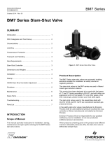
Figure 1. Type VFA-MR Buttery Valve
The following versions are available:
VFA : Lever operated
VFA-MR : Gear operated
VFA-MRO : Gear operated for use with absorbing
odorizing systems
P.E.D. CATEGORIES AND FLUID GROUP
This product is Pressure Equipment classied in the following
categories in according to Directive 97/23/EC PED.
Table 1. P.E.D. Categories And Fluid Group
Type CATEGORY FLUID GROUP
DN 50 PN 16 - ANSI 150
I
1
DN 65 ÷ 150 PN 16 - ANSI 150
II
DN 200 PN 16
II
DN 250 PN 16
III
DN 200 ÷ 250 ANSI 150
III

VFA Series
2
CHARACTERISTICS
Body Sizes and End Connection Styles
VFA • VFA-MR • VFA-MRO
DN 50 - 65 - 80 - 100 - 125 - 150 - 200 - 250
PN 16 - ANSI 150 anged
!
WARNING
The pressure/temperature limits indicated
in this instruction manual or any applicable
standard or code limitation should not be
exceeded.
Maximum Operating Inlet Pressure
PN 16: 16 bar
ANSI 150: 19 bar
At average ambient temperature.
Minimum/Maximum Allowable Temperature (TS)
See label
Temperature
Standard Version: Working -10° to 60°C
Low Temperature Version: Working -20° to 60°C
Materials
Body: Steel
Disk: Pressed steel
Shaft: Stainless steel
Gaskets: Nitrile NBR rubber (FKM on request)
LABELLING
Note 1
Note 2
Note 3
Note 41.5
MATRICOLA
SERIAL Nr.
Cvm
TIPO
TYPE
ANNO
YEAR
Gruppo Fluido
Fluid Group
°C
PT=PS
TS
DN
ANSI
PN
xPSbarbar
xxxx
body
Notified
BOLOGNAITALY
Figure 2. Label for VFA Series
Note 1: See “Characteristics”
Note 2: Year of manufacture
Note 3: Temperature class
-10°/60°C or -20°/60°C
Note 4: PN 16 PS: 16 bar
ANSI 150 PS: 19.3 bar
The Category I pressure equipments will not have on label
any Notied Body reference.
OVERPRESSURE PROTECTION
The recommended safety pressure limitations are stamped on
the valve nameplate (PS). Some type of overpressure protec-
tion is needed if the actual inlet pressure exceeds this limits.
Personal injury, equipment damage, or leakage due to es-
caping uid or bursting of pressure-containing parts may re-
sult if this relief valve is over-pressured or is installed where
service conditions could exceed the design operative limits.
Valves operation below the maximum pressure limitations
does not preclude the possibility of damage from external
sources or debris in the line.
The valves should be inspected for damage after any over-
pressure condition..
TRANSPORT AND HANDLING
Established transport and handling procedures shall be fol-
lowed to avoid any damage on the pressure containing parts
(valve body) by shocks or anomalous stresses.
In case of necessity of a harness, a nylon harness will have
to be used in order to protect the surface and possible valve
accessories.
ATEX REQUIREMENTS
!
WARNING
If the provisions of EN 12186 & EN 12279,
national regulations, if any, and specic
manufacturer recommendations are not put
into practice before installation and if purge
by inert gas is not carried out before equip-
ment’s start-up and shut-down operations,
a potential external and internal explosive
atmosphere can be present in equipment &
gas pressure regulating/measuring stations/
installations.

VFA Series
3
If a presence of foreign material in the pipelines is foreseen
and purge by inert gas is not carried out, the following
procedure is recommended to avoid any possible external
ignition source inside the equipment due to mechanical
generated sparks :
• drainage to safe area via drain lines of foreign materials, if
any, by inow of fuel gas with low velocity in the pipe-work
( 5m/sec)
In any case,
• provisions of Directive 1999/92/EC and 89/655/EC shall
be enforced by gas pressure regulating/measuring station/
installation’s end user
• with a view to preventing and providing protection against
explosions, technical and/or organizational measures
appropriate to the nature of the operation shall be taken
(e.g. : lling/exhausting of fuel gas of internal volume
of the isolated part/entire installation with vent lines
to safe area - 7.5.2 of EN 12186 & 7.4 of EN 12279 ;
monitoring of settings with further exhaust of fuel gas to
safe area ; connection of isolated part/entire installation to
downstream pipeline; ….)
• provision in 9.3 of EN 12186 & 12279 shall be enforced by
pressure regulating/measuring station/installation’s end user
• external tightness test shall be carried out after each
reassembly at installation site using testing pressure in
accordance with national rules
• periodical check/maintenance for surveillance shall be
carried out complying with national regulations, if any, and
specic manufacturer recommendations.
DN A
B
C D E F G H
WEIGHT
PN 16 ANSI 150 VFA
VFA-MR
VFA-MRO
50 43 136 173 147
470 160
190
125 120
11.5 14
65 46 139 189 157 200 14 16
80 46 149 189 163 205 18 20
100 52 159 208 174 215 21 23
125
56 169 237
209
490
300
335
300 168
28.5 35
150 227 345 36 42
200 60 187 267 252 375 51 57
250 68 214 278 239 530 430 97 103
A
B
A
B
DN
DN
C
F
D
VFA SERIESVFA-MR AND VFA-MRO SERIES
G
HE
Table 2. VFA Series Dimensions (mm) and Weights (kg)
Figure 3. VFA Series Dimensions
DIMENSIONS AND WEIGHTS

VFA Series
4
INSTALLATION
!
WARNING
Only qualied personnel should install or
service a buttery valve.
Buttery valves should be installed, oper-
ated, and maintained in accordance with
international and applicable codes and regu-
lations, and Emerson instructions.
Clean out all pipelines before installation of
the regulator and check to be sure the regu-
lator has not been damaged or has collected
foreign material during shipping.
Possible fails that cause the shutdown of the
valve can create hazard conditions.
Personal injury, equipment damage, or
leakage due to escaping uid or bursting of
pressure-containing parts may result if this
valve is over pressured or is installed where
service conditions could exceed the limits
given in the Specications section, or where
conditions exceed any ratings of the adja-
cent piping or piping connections.
Additionally, physical damage to the valve
could result in personal injury and property
damage due to escaping uid. To avoid such
injury and damage, install the regulator in a
safe location..
To avoid this, install the buttery valve:
• In a safe area where the is protected from exposure to
physical damage and/or corrosive substances
• service conditions are within valve capabilities
Don’t exceed any ratings of the adjacent anges or piping
connections.
Install the valve in any position desired, unless otherwise
specied, but be sure ow through the body is in the direction
indicated by the arrow on the body.
If using a VFA series buttery valve on hazardous or am
-
mable gas service, personal injury and property damage
could occur due to re or explosion of vented gas that may
have accumulated.
To prevent such injury or damage, provide piping or tubing to
vent the gas to a safe, well-ventilated area in accordance also
with international and applicable codes and regulations. In
particular, when venting a hazardous gas, the piping or tubing
should be located far enough away from any buildings or win-
dows so to not create a further hazard, and the vent opening
should be protected against anything that could clog it.
For outdoor installations, the buttery valve should be located
away from vehicular trafc.
In order to avoid damaging of the valve disc, special care has
to be done in carrying out accurate measurements to assess
that it can rotate in the ange of connection and in the pipe
without difculties.
Furthermore, center correctly the valve on the connection
anges.
A suggested bolt tightening sequence is to process “three
o’clock, nine o’clock, twelve o’clock, six o’clock, etc.”. Not ap
-
ply never the pressure to only partially installed valve.
Further the ENs 12186 & 12279, where this product is used :
• provide the cathodic protection and electrical isolation to
avoid any corrosion
SHUTDOWN
!
WARNING
To avoid personal injury resulting from sud-
den release of pressure, isolate the valve
from all pressure before attempting disas-
sembly and release trapped pressure from
the equipment and pressure line.
In case of disassembly of main pressure
retaining parts for checks and maintenance
procedures, external and internal tightness
tests have to be done according to appli-
cable codes.
MAINTENANCE
(See Figure 4 and 5)
!
WARNING
All maintenance procedures must be carried
out only by qualied personnel.
If necessary, contact our technical support
representatives or our authorized dealers.
Buttery valve and its pressure accessories are subject
to normal wear and must be inspected periodically and
replaced as necessary.

VFA Series
5
The frequency of inspection/checks and replacement
depends upon the severity of service conditions and upon
applicable codes and national standards/rules .
In accordance with applicable National or Industry codes,
standards and regulations/recommendations, all hazards
covered by specic tests after nal assembling before
applying the CE marking, shall be covered also after every
subsequent reassembly at installation site, in order to ensure
that the equipment will be safe throughout its intended life.
Before proceeding with any maintenance work, shutoff the
gas upstream and downstream from the regulator, also
ensure that there is no gas under pressure inside the body
by loosening the upstream and downstream connections.
Upon completion, check for leaks using suds.
General Maintenance
a. Turn valve to “close” position and remove “open” control.
Servicing mode will depend on the type of valve control.
b. Remove screws (key 23 for sizes DN 50 to DN 200 and
key 27 for DN 250), slide off valve body from pipe and
replace O-ring (key 7). Note: It may sometimes be neces-
sary to widen counteranges so as to remove valve.
c. Remove screws (key 12), hub (key 1) and upper bushing
(key 9), and replace O-ring (key 13 and 14).
d. On sizes DN 50 to DN 200: Remove dowels (key 6).
On size DN 250: Remove bush (key 22), pin (key 6) and
replace O-ring (key 20 and 21) if worn.
e. Remove shaft (key 4).
f. Remove disk (key 8).
g. Remove screws (key 11) and plate (key 5).
h. Replace gasket unit (key 3) and O-ring (key 6) if worn.
i. On sizes DN 125 to DN 200: remove screws (key 17),
plug (key 19) and replace O-ring (key 18 and 24).
On size DN 250: remove screws (key 19), plug (key 17)
and replace O-ring (key 18, 23 and 7).
Reassembly
Lubricates all seals with “MOLYKOTE 55 M” molybdenum
grease.
Use the greatest care to avoid damage to seals.
Reassemble by reversing the above steps.
Tighten all screws uniformly to ensure proper sealing.
SPARE PARTS
Spare parts storage shall be done by proper procedures
according to national standard/rules to avoid over aging or
any damage.

VFA Series
6
PARTS LISTS
VFA Series DN 50 to DN 200
(See Figure 4)
Key Description
1 Hub
2 Body
3* Gasket unit
4 Shaft
5 Plate
6 Dowel
7* O-ring
8 Disk
9 Upper bushing
10 Lower bushing
11 Screw
12 Screw
13* O-ring
14* O-ring
15 Label
16 Rivet
17 Screw
18* O-ring
19 Plug
20* Gasket
21 Flange
22 Washer
23 Screw
VFA Series DN 250
(See Figure 5)
Key Description
1 Hub
2 Body
3* Gasket unit
4 Shaft
5 Plate
6 Pin
7* O-ring
8 Disk
9 Upper bushing
10 Lower bushing
11 Screw
12 Screw
13* O-ring
14* O-ring
15 Label
16 Rivet
17 Plug
18* O-ring
19 Screw
20* O-ring
21* O-ring
22 Bush
24* Gasket
25 Flange
26 Washer
27 Screw
Rubber parts marked with (*) are supplied in the “spare parts
kit”, recommended as stock.
To order the kit it is necessary to communicate to us the type
of the valve and its serial number.

VFA Series
7
VFA/125/150/200 PLUG DETAIL
1
4
12
15 16
B
B
SECTION B-B
SECTION A-A
24
1810
1719
A
A
9
13
14
3
8
10
7
5
2
6
11
20
21
22
23
SCHEMATIC ASSEMBLIES
Figure 4. VFA Buttery Valve DN 50 to DN 200
LM/7124

VFA Series
The Emerson logo is a trademark and service mark of Emerson Electric Co. All other marks are the property of their prospective owners. Tartarini is a mark of O.M.T. Ofcina Meccanica Tartarini s.r.l.,
a business of Emerson Process Management.
The contents of this publication are presented for informational purposes only, and while every effort has been made to ensure their accuracy, they are not to be construed as warranties or guarantees,
express or implied, regarding the products or services described herein or their use or applicability. We reserve the right to modify or improve the designs or specications of such products at any
time without notice.
Emerson Process Management Regulator Technologies, Inc., does not assume responsibility for the selection, use or maintenance of any product. Responsibility for proper selection, use and
maintenance of any Emerson Process Management Regulator Technologies, Inc., product remains solely with the purchaser.
©Emerson Process Management Regulator Technologies, Inc., 2015; All Rights Reserved
Industrial Regulators
Emerson Process Management
Regulator Technologies, Inc.
USA - Headquarters
McKinney, Texas 75070, USA
Tel: +1 800 558 5853
Outside U.S. +1 972 548 3574
Asia-Pacic
Shanghai 201206, China
Tel: +86 21 2892 9000
Europe
Bologna 40013, Italy
Tel: +39 051 419 0611
Middle East and Africa
Dubai, United Arab Emirates
Tel: +971 4811 8100
For further information visit www.emersonprocess.com/regulators
Natural Gas Technologies
Emerson Process Management
Regulator Technologies, Inc.
USA - Headquarters
McKinney, Texas 75070, USA
Tel: +1 800 558 5853
Outside U.S. +1 972 548 3574
Asia-Pacic
Singapore 128461, Singapore
Tel: +65 6777 8337
Europe
O.M.T. Tartarini s.r.l. Via P. Fabbri 1,
I-40013 Castel Maggiore (Bologna), Italy
Tel: +39 051 419 0611
Francel SAS, 3 ave Victor Hugo,
CS 80125 - Chartres 28008, France
Tel: +33 2 37 33 47 00
Middle East and Africa
Dubai, United Arab Emirates
Tel: +971 4811 8100
TESCOM
Emerson Process Management
Tescom Corporation
USA - Headquarters
Elk River, Minnesota 55330-2445, USA
Tels: +1 763 241 3238
+1 800 447 1250
Asia-Pacic
Shangai 201206, China
Tel: +86 21 2892 9499
Europe
Selmsdorf 23923, Germany
Tel: +49 38823 31 287
O.M.T. Ofcina Meccanica Tartarini S.R.L., R.E.A 184221 BO Cod. Fisc. 00623720372 Part. IVA 00519501209 N° IVA CEE IT 00519501209,
Cap. Soc. 1.548 000 Euro i.v. R.I. 00623720372 - M BO 020330
Francel SAS, SIRET 552 068 637 00057 APE 2651B, N° TVA : FR84552068637, RCS Chartres B 552 068 637, SAS capital 534 400 Euro
Figure 5. VFA Buttery Valve DN 250
4
1
9
8
13
2
14
18
23
18
17
7
11
22
21
6
20
5
262524 27
19
PLUG DETAIL
HUB DETAIL
12
LM/7125
/


