Page is loading ...

Berkeley Care Manual
H 806
H 806
1353 1094
293 Wright Street
Delavan, Wisconsin U.S.A. 53115
1-888-BERKELEY
Mississauga, Ont., Canada
1-800-363-PUMP
B1521 © 1994, Sta-Rite Industries, Inc.
R
J
1
9
L
M
O
N
O
F
F
B E R K E L E Y
B E R K E L E Y
881 0494
868 0494

2
Introduction
This Care Manual was designed as a general guide to Berkeley centrifugal
pumps and is not intended to be used as an Engineering Specifications
Manual.
All subjects covered, whether written or illustrated, are suggestions by
Berkeley Pumps to aid in the proper installation and operation of end suction
centrifugal pumps and apply to no particular application.
Questions on specific application and/or installation procedures,
maintenance, and repair, should be directed to the nearest Berkeley
Professional Dealer.
Table of Contentsx
Page
• Introduction .........................................................................................................2
• Section 1: Installation....................................................................................3-14
• Section 2: Start-up.......................................................................................15-19
• Section 3: Maintenance...............................................................................20-28
• Section 4: Pump Nomenclature .................................................................29-35
Watch for this symbol
Component damage can occur when excessive force is applied
during assembly, disassembly, repair, or maintenance. Generally,
components do not need to be forced on or off during these
procedures. Use care at all times to protect the physical integrity
of all pump components.

3
SECTION 1
Contents
Installation
Page
• Suction Connection, Suction Lift – Recommended ................................4
• Suction Connection, Suction Lift – Not Recommended.........................5
• Suction Connection, Flooded Suction – Recommended .......................6
• Suction Connection, Flooded Suction – Not Recommended.................7
• Discharge Connection – Recommended................................................8
• Discharge Connection – Not Recommended.........................................9
• Pump Foundation ..................................................................................10
• Pump Protection, Pump House / Shelter ..............................................11
• Shaft Alignment Belt / Coupling Drive...................................................12
• Protect Your Investment ..................................................................13,14

INSTALLATION
Suction Lift
Suction Connection
4
503 0194
Short length of straight pipe after reducer.
( 2 times pipe diameter minimum )
Suction
Gauge
Straight run, short as possible but
at least 6 times pipe diameter ("D")
after elbow to stabilize flow.
As close
as possible
Pipe diameter ("D")
4 x "D"
minimum
1 x "D" minimum
from bottom
Strainer / Foot Valve
To keep debris from entering
pump suction and to maintain
pump prime after shut-off.
Eccentric Reducer
flat side up.
See foundation
section.
Support pipe
as required
NOTICE: All connections
must be air tight.
For Han-Dee Primer
connection, see start-up.
Standard or long
radius elbow.
Slope upward
to pump.
• Use pipe, tubing, or reinforced hose to make
suction connection. Hose must have suffi-
cient strength to resist collapse under the
atmospheric pressure differential that occurs
while pump is running.
• Piping run and connection fittings should be
properly aligned and independently support-
ed to reduce strain on pump case.
• Suction pipe size should be at least one
commercial pipe size larger than opening of
pump inlet. Flow velocity should not exceed
8 ft./sec.
• Suction screen must screen out solids that
could clog pump impeller.
• Suction screen area must be at least four
times suction pipe area.
• Net Positive Suction Head Available
(NPSHA) must exceed Net Positive Suction
Head Required (NPSHR) by the pump or
reduced performance and severe pump
damage may result.
• All suction piping must have a continuous
rise to the pump suction inlet. A 1/4 inch per
foot minimum slope is recommended.
Recommended

Suction Lift
Suction Connection
5
INSTALLATION
505 0194
Do not use
Concentric
Reducer.
Concentric Reducer causes high spots
along the suction line resulting in air pockets.
Do not install valves
in suction line.
Long run
not recommended
Unsupported
pipe causes
excessive stress
on pump and fittings.
Excess use of pipe fittings
means potential air leaks.
No support or
uneven mounting
not recommended.
Pipe diameter
("D") undersized
reduces performance
High suction
lift should
be avoided.
Less than
4 x "D"
Vortex caused by
insufficient submergence
may cause pump to
lose prime.
No strainer
may cause
pump to
clog.
Insufficient bottom
clearance
Elbow immediately in
front of pump intake
not recommended.
• Suction pipe sloping downward to pump inlet
will trap air which will reduce performance and
may cause pump to lose prime.
• Suction piping that is undersized will create
excess friction losses that may cause cavitation
and a reduction in pump performance.
• Excess fittings and bends in suction line results
in trapped air, reduced performance, and high
friction losses which may cause cavitation.
NOT Recommended

6
INSTALLATION
Suction Connection
When flooded suction exists
702 0294
Water under
pressure
Support pipe
as required
Short run of straight pipe after reducer
(2 times pipe diameter).
Eccentric Reducer
flat side up.
Maintain minimum liquid
level to prevent vortexing.
Isolation Valve
full open when
pumping.
Standard or
long radius
elbow.
Suction
Gauge
Straight run, short as possible but
at least 6 times pipe diameter after
pipe fitting to stabilize flow.
Slope upward to pump.
• Use pipe, tubing, or reinforced hose to make suc-
tion connection. Hose must have sufficient
strength to resist collapse under the atmospheric
pressure differential that may occur while pump is
running.
• It is important, even with a flooded suction condi-
tion, that proper pipe fittings are used so water is
delivered to impeller eye with a smooth flow and
constant velocity.
• Suction pipe size should be at least one commer-
cial pipe size larger than opening of pump inlet.
Flow velocity should not exceed 8 ft./sec.
• An isolation valve is used in a pressurized suction
pipe to permit servicing pump.
• Piping run and connection fittings should be prop-
erly aligned and independently supported to
reduce strain on pump case.
• If solids are present, a strainer should be used to
protect the pump.
Recommended

7
Suction Connection
INSTALLATION
When flooded suction exists
703 0294
Water under
pressure
Inverted Eccentric Reducer
may result in air pocket.
Do not leave
valve partially
closed.
Check Valve
in suction pipe
not needed.
Unsupported
pipe causes
excessive stress
on pump and fittings.
Concentric Reducer may
cause air pockets.
Elbow immediately in front
of pump intake not recommended.
Valve in upward
position may trap
air.
Miter elbow or short
radius elbow not
recommended.
• Suction piping that is undersized will create
excess friction losses that may cause cavitation
and a reduction in pump performance.
• Excess fittings and bends in suction line results
in trapped air, reduced performance and high
friction losses which may cause cavitation.
• If a check valve is required for back flow preven-
tion, locate on the discharge side of pump.
NOT Recommended

8
INSTALLATION
Discharge Connection
Expansion joint with tie
rods where needed.
Use Concentric Reducer
to mimimize friction losses.
This fitting may be used to
check shut-off head.
Isolation
Valve
Support piping
as required
This view shows discharge
fittings typical of pump
with flooded suction.
These two views show discharge
fittings typical of pump with
suction lift.
Discharge pipe diameter at
least one nominal pipe size
larger than discharge opening
in pump.
Non-Slam or
spring loaded
check valve.
Isolation valve to
permit servicing of
check valve or pump.
Discharge
Priming
Valve
Align piping to
minimize flange
stress.
706 0294
Pressure
Gauge
• Use pipe, tubing, or reinforced hose to make
discharge connection. Material selected must
have sufficient strength for operating pressures.
• Discharge pipe should be sized so that flow
velocity is below 8 ft./sec.
• Use only non-slamming check valves to prevent
hydraulic shock (water hammer).
• Use gate, ball, or butterfly valve for isolation.
Valve should be full open during operation.
• Maintain proper pipe size throughout discharge
system, using as few elbows and tees as possi-
ble to keep friction loss to a minimum.
• Install pressure gauge after reducer as shown
to check operating pressure.
Recommended

9
INSTALLATION
Discharge Connection
• Avoid excess friction loss caused by numerous
fittings, insufficient pipe diameter, and sharp turns
in pipe run.
• Some swing type check valves may permit build-
up of reverse velocity before closing causing
hydraulic shock or “water hammer”.
Do not use Gate Valve
to throttle flow.
Avoid abrupt change
in pipe size.
708 0294
Avoid undersized
pipe diameter.
Do not force alignment
that can cause flange
stresses.
Do not leave
pipe unsupported.
Avoid check valves
that cause hydraulic
shock.
NOT Recommended

10
INSTALLATION
Typical Installations
Pump Foundation
Drainage
Drainage
Pump or
Motor Frame
1/2" or thicker
Sole Plate tapped
for hold down bolts
Anchor
Bolts
Concrete Foundation
Pump or
Motor Frame
Shims
for alignment
Anchor
Bolt
Steel
Channel
Concrete
Foundation
Grout
Grout
Dam
Drainage
Wedges
Various Heights
Concrete
Foundation
Shims
797 0394
Tack
Weld
• There are several types of permanent pump/
foundation installations in use. Those pictured
above are typical.
• If grout is used, top of concrete should be left
rough to provide a good bonding surface.
• Foundation should slope away from pump to
prevent liquid from pooling.

11
INSTALLATION
Pump House
Pump Protection
To Pump
Suction
To Pump
Discharge
Provide proper support
for all pipe runs.
From water
source
To water
service
Large door(s)
for installation
and servicing
Forced air ventilation
is recommended
Allow for proper
drainage
934 0594
Removable
for service
A
i
r
M
o
v
e
m
e
n
t
935 0594
• Check local codes for all electrical connections.
• Check local codes for all plumbing connections.
• Allow adequate room around pump for servicing.
• Allow for water drainage inside pump house (floor
drains).
• Allow for heating capabilities if pump is running
year round.
• Pump shelter with removable roof protects pump
from rain, dust, plants, and the sun. Locate shelter
to avoid flooding.
• Proper ventilation is a must.
• Allow for proper drainage away from pump and
motor.
• Check local codes for all electrical connections.
• Check local codes for all plumbing connections.
Pump Shelter

12
INSTALLATION
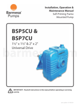
Coupling Alignment
Shaft Alignment
• Belt guard is not shown for pictorial clarity.
Never
operate pump without proper guard or
shroud in place.
• For proper belt tension, check belt manufac-
turer’s specifications.
H 806
H 806
Centerline
Centerline
A
A
B
B
B
B
Incorrect
Centerline - A of each shaft and pulley must
be parallel for proper alignment.
Incorrect
Centerline - B represents center of belt and
pulley.This centerline must be straight for
proper alignment.
937 0594
A
A
• Standard Method:
Use a caliper or straight edge to check for proper
alignment. Check four places, 90 degrees apart.
• Preferred Method:
Use a commercially available dial indicator to
check for proper alignment. Refer to coupling
I.O.M. for detailed instruction.
• Coupling guard shown in phantom for pictorial
clarity.
Never
operate pump without guard or
shroud in place.
936 0594
See standard or preferred
method descibed below.
H 806
H 806
Centerline
B.Perry
Caliper
Straight Edge
Belt Drive

13
INSTALLATION
Electrical
Protect Your Investment
884 0494
1
2
3
AMP TIME
4
5
Incoming Power
L1 L2 L3
AUTO
STOP
HAND
START
• Minimum recommended components to protect
your pump during operation are listed above.
Check all local electrical codes prior to
installation.
Contactor
Lightning Arrestor
Loss of Prime Protection
Fuseable Disconnect
Starter
1
2
3
4
5

14
INSTALLATION
Typical Installation
Protect Your Investment
BERKELEY
1155 0794
Misalignment Sensing Probe and Switch for Centrifugal Pumps
• This probe is designed to minimize damage if thrust bearing wear or impeller
separation threaten your pump. When installed and adjusted properly, the
probe senses slight axial movement of the rotating impeller. Unsafe move-
ment abrades the tip of the probe, completing a circuit to shut down the
power source (diesel or gas engine, or electric motor).
This protective probe circuit can also be configured to include a visual or
audible warning device.

15
SECTION 2
Contents
Start-up
Page
• Pump Priming....................................................................................16,17
• Determine Pump Rotation ....................................................................18
• Start-up Check List................................................................................19

16
START-UP
Pump Priming
Primer Isolation
Valve
Berkeley Discharge
Priming Valve or
Butterfly Valve.
787 0394
Han-Dee
Primer
Suction to
Water Source
For Engine Exhaust Type Primer
Locate connection at least
one pipe diameter from
pump case.
Suction Lift with Priming Pumpx
• Close air tight valve on discharge.
• Han-Dee Primer operation:
1. Open Han-Dee Primer isolation valve.
2. Work handle of Han-Dee primer up and down to
evacuate air from the suction line. (Refer to
primer owner’s manual for proper procedure).
3. When water flows freely from primer, close Han-
Dee Primer isolation valve. (Pump case should
now be filled with water).
• Immediately start pump.
• Slowly open butterfly valve (if used) until desired
flow is achieved. (Discharge Priming Valve will
open automatically).
Suction Lift with Enginei
Exhaust Primeri
• Locate exhaust primer connection as shown
above.
• For operation, refer to specific instructions included
with exhaust primer.

17
START-UP
Pump Priming
Hydraulically Balanced Pumpsx
• Hydraulically balanced pumps operate with a very
low positive pressure across the stuffing box, per-
mitting a much looser fit of the packing rings
around the shaft sleeve to control the loss of water
from the pump through the stuffing box. Because
of the looser fit of the packing rings, air can be
more easily drawn into the pump through the stuff-
ing box when priming the pump with an air evacu-
ation type primer.
• A grease fitting, communicating through the side of
the stuffing box to a lantern ring in the packing set,
is provided to grease seal the stuffing box to pre-
vent air leakage during priming.
• If pump cannot be primed due to air leakage
through the stuffing box,
DO NOT
tighten packing.
Instead, pump grease into fitting until back pres-
sure occurs, forcing grease into lantern ring to seal
the stuffing box. After priming, when unit is put into
operation, the grease will be flushed out through
the packing by water flowing outward through the
stuffing box. Proceed with normal adjustment of
the packing as described in pump owners manual.
Note that the grease seal is used
only
for control
of air leakage during priming, and that
only
the
packing gland is used to control the flow of water
through the stuffing box during normal operation.
Suction Lift with Foot Valve
x
• Close air tight valve on discharge.
• Remove pipe plug from highest opening in pump
case.
• Completely fill pump and suction piping with water.
• Rotate shaft slowly to allow any air trapped in
impeller to escape.
• When all air has been forced out of pump, replace
pipe plug. Use pipe joint compound on plug
threads and tighten as necessary to prevent
leakage.
Flooded Suctionx
• Close air tight valve on discharge.
• Open air vent (or pipe plug) in the highest tapped
opening in pump case.
• Open inlet isolation valve, allowing water to fill the
pump completely and force all air out through vent.
• Rotate shaft slowly to allow any air trapped in
impeller to escape.
• Close vent opening when water without air
emerges.

18
START-UP
Determine Pump Rotation
Viewed from
this direction
Viewed from
this direction
Pump with a
Clockwise
Rotation
Pump with a
Counter-Clockwise
Rotation
C
l
o
c
k
w
i
s
e
r
o
t
a
t
i
o
n
H 806
H 806
H 806
H 806
As viewed
938 0594
12
6
39
As viewed
12
6
39
C
o
u
n
t
e
r
-
C
l
o
c
k
w
i
s
e
• Electric Motors:
Single Phase: Refer to wiring information on the
motor plate to obtain proper rotation.
Three Phase: If pump runs backward, reverse any
two leads coming off incoming power (L1, L2, L3)
until proper rotation is obtained. (ie: reverse L1
and L2, L2 and L3, or L1 and L3).
• Note: It is common for many motor and engine
manufacturers to indicate rotational direction in the
opposite manner as the pump standard. That is,
they refer to the rotation as viewed from the front
of motor or engine. Pump rotation is determined
by viewing from the back.
• Pump running backward – A centrifugal pump will
still pump liquids, however, GPM and head will be
a fraction of the published performance.
Pump Rotation is determined as clockwise or counter-clockwise
by viewing liquid end of pump from the back or shaft side, and
NOT
from looking into the impeller eye or front of volute.
Pump Rotation
must
be verified after installation.

19
START-UP
Check List
■■
Read and be familiar with the pump Installation, Operation and Maintenance
Manual. Check to see that all aspects of these instructions have been com-
plied with.
■■
Pipe connections must be securely fastened and air tight. All piping must be
clean and free of debris.
■■
Is pump and all piping properly supported and are all supports securely fas-
tened?
■■
Are required screens in place?
■■
Are all valves in the system in the proper open or close position for start-up?
■■
Confirm power source voltage matches the motor nameplate.
■■
Verify that belt or coupling alignment is properly adjusted if applicable, and
that all safety guards are in place.
■■
Does the impeller / shaft rotate freely?
■■
Is pump primed?
■■
Verify that rotational direction is correct for pump by VERY short “on-off” of
power source.
■■
Slowly open discharge valve to obtain desired flow rate of pumping system.
Do not start pump until above checks have been
made and all start-up instructions in the pump I.O.M.
have been complied with. Failure to do so may result in severe damage to
equipment, cause personal injury, and may void warranty.

20
MAINTENANCE
Maintenance Record
/