Dakota Digital SLX-01-2 Technical Manual

Type
Technical Manual

This manual is also suitable for

Dakota Digital SLX-01-2 offers a range of capabilities to enhance your driving experience and provide valuable information. Here are some key features:

  • Performance Monitoring: The SLX-01-2 tracks and displays essential performance data such as speed, distance traveled, and elapsed time.

  • Trip and Service Mileage Tracking: Keep tabs on your trips and service intervals with the resettable trip mileage and service mileage features. Easily monitor miles driven since the last reset or service.

  • High-Speed Recall: Capture and store your vehicle's top speed, allowing you to recall and reset it as desired.

Series II
ODYR-01-1, ODYR-01-2, SLX-01-1, & SLX-01-2
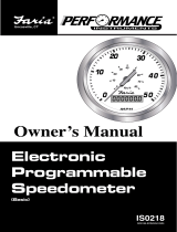
PERFORMANCE SPEEDOMETER
Introduction:
The Odyssey Series II gauges from Dakota Digital, Inc. incorporates the reliability and quality of our
standard gauges, along with several unique features and easy mounting. These features include:
Industry standard 3-3/8” gauge size.
Push button speedometer calibration.
Million mile odometer.
Resettable trip mileage.
Resettable service mileage.
0-60 timer.
High speed recall.
Gear shift indicator. (requires GSS-1000
sender).
Microprocessor stabilized readings.
Night dimming with lens label lighting.
Non-Glare, high contrast lens
High Visibility VFD display for sunlight readability.
WIRING COLOR CODE FOR GAUGE:
RED +12 volt power with key on
BLACK ground for gauge
PURPLE high beam indicator
ORANGE left turn indicator
GREEN right turn indicator
GRAY speed signal input
WHITE/RED speed sensor power out (if required)
BROWN gear shift sender input
BLUE night dimming
POWER
Connect the red wire from the main harness to accessory power from the ignition switch.
Never connect this to a battery charger alone. It needs to have a 12 volt battery connected to it. Battery
chargers have an unregulated voltage output that will cause the system to not operate properly.
GROUND
The black wire is the main ground for display system. A poor ground connection can cause improper or
erratic operation.
TURN SIGNAL & HIGH BEAM INDICATORS
The right turn, left turn, and high beam indicators are activated by 12 volts at their respective hook-up
wires. The right turn signal wire is green, the left turn signal wire is orange, and the high beam wire is purple.
These can be connected to the same wires that the indicator lights would be connected to. The display system
wire colors may not match the wire colors in your electrical wire harness.
SPEEDOMETER
The gray wire connects to the vehicle speed sensor. For two wire pulse generators attached to a
speedometer cable, attach one wire from the sensor to the speedometer ground and connect the other to the gray
wire. If the signal is being shared by a cruise control or ECM, make sure they all use a common ground for the
pulse generator.
For inductive pickup’s, connect one terminal from the pickup to ground and connect the other terminal to
the gray wire on the gauge.
For 3 wire Hall-effect sensors, refer to the installation instructions for the sensor to determine wire color
code. Most 3 wire sensors use the following color code: RED – power, BLACK – ground, WHITE – speed signal.
Connect the speed signal wire to the gray wire on the gauge, connect the speed power wire to the white w/red
stripe, and connect the speed ground wire to the black wire.
For speed sensor integrated into a vehicle wiring harness, consult a service manual to determine the color
code and location of the speedometer signal.
The speedometer is fully adjustable and calibration is discussed below.
SPEEDOMETER CALIBRATION
Failure to calibrate the speedometer may cause your odometer mileage to increase very rapidly.
The speedometer calibration is done using the function switch. The speedometer can be calibrated two
different ways. The first method is to place the unit in auto-cal mode and drive exactly one mile (one km for metric).
The second method is to place the unit in adjust mode and the speed reading can be moved up or down while
driving.
METHOD 1, AUTOCAL
1. Make sure the key is off so the gauge is not powered.
2. Press and hold the function switch.
3. Turn the key on. With the switch still held, start the engine. The display will show “ -- “.
4. Release the function switch. The display will switch between “AUtO” (auto cal) and “AdJ”. The odometer will
show “SELECt”
5. When “AUtO” is displayed press the function switch. This will place the unit in auto calibration mode.
6. Release the function switch. The odometer display will show all zeroes.
7. Drive exactly one mile (or 1km). The odometer will show the number of signal pulses received from the speed
sensor.
8. Press and release the function switch. The calibration value will be calculated and stored. The gauge will now
restart in normal mode with the new speed calibration.
METHOD 2, ADJUST SPEED
1. Make sure the key is off so the gauge is not powered.
2. Press and hold the function switch.
3. Turn the key on. With the switch still held, start the engine. The display will show “ -- “.
4. Release the function switch. The display will switch between “AUtO” (auto cal) and “AdJ” (adjust). The
odometer will show “SELECt”
5. When “AdJ” is displayed press the function switch. This will place the unit in calibration adjustment mode.
6. Release the function switch. The display shows the speed and the odometer will show “AdJUSt”
7. Drive at a known speed. Following another vehicle that is driving at a constant, known speed can do this.
8. Press the function switch. The speed reading will begin increasing until the function switch is released. The
next time the function switch is pressed, the speed reading will begin decreasing until it is released.
9. Once the speedometer is reading correct release the function switch. The new calibration will be saved if no
adjustments are made for 7-10 seconds.
FUNCTION SWITCH
The function switch on the front of the speedometer allows access to all of the mileage and performance
information. Pressing and releasing the function switch toggles through the different displays. The display
sequence is as follows:
ODOMTR > 000000 odometer mileage
TRIP > T 000.0 trip meter mileage
HI SPD > HI 00 high speed recall
60 TIM > 60 00.0 0-60mph time
SERVIC > S 0000 miles since last service
GEAR > current gear position
The gear display is only available when a GSS-1000 universal gear shift sender is connected to indicate what gear
the automatic transmission is in.
Each of the displays are described in more detail here:
ODOMTR
The odometer keeps track of and stores the miles driven. No power is required to maintain the memory
stored internally. The odometer has a range of 0 – 999,999miles.
TRIP
The trip odometer keeps track of miles driven since the last reset. The trip mileage is reset to zero by
pressing and holding the function switch while the trip mileage is displayed. The trip mileage has a range
of 0 – 999.9 miles.
HI SPD
The high speed recall keeps track of the highest speed reached. This is reset to zero each time the
speedometer is turned on and can also be reset by pressing and holding the function switch while the hi
speed is displayed.
60 TIM
The 0-60 timer times how long it takes to go from 0mph to 60mph. The timer is reset to zero each time the
speed goes to zero and starts as soon as the vehicle begins moving. If the time reaches 25.5 seconds
before the speed gets to 60 the timer will stop.
SERVIC
The service mileage can be used to keep track of the miles traveled since the last oil change or service. It
is reset to zero by pressing and holding the function switch while the service mileage is displayed. The
service mileage has a range of 0-9,999 miles.
GEAR
The gear shift display will show the current gear the transmission is in when used with a GSS-1000. The
brown wire from the gauge should connect to the “First” terminal on the GSS-1000. Refer to the GSS-1000
instructions for sensor setup. The gear labels are “PARK”, “REVRSE”, “NEUTRL”, “OVRDRV”, “DRIVE”,
“SECOND”, and “FIRST”. If the gear is changed while another function is being displayed, the readout will
automatically switch to the gear display for a few seconds.
NIGHT DIMMING
Your display system has a dimming feature that dims the display intensity. Normally the system is at full
brightness for daytime viewing. When the blue wire has 12 volts the display intensity will be reduced. Connect this
to a park light or tail light circuit, then whenever the headlights are on the display will dim. To have the system at
full brightness all of the time leave the blue wire disconnected.
MOUNTING:
The gauge requires a round hole 3-3/8” in diameter. It should be inserted into the opening from the front
and the U-clamp will be installed from the back. Tighten the two nuts on the U-clamp so that the gauge is secure.
Troubleshooting guide.
Problem Possible cause Solution
Gauge will not light up Red wire does not have Connect to a location that has power.
power.
Black wire is not getting Connect ground to a different location.
a good ground.
Gauge is damaged. Return gauge for repair. (see instructions)
Gauge lights up, but displays Speed calibration is invalid Gauge must be recalibrated (see instructions).
“Spd” “Err”
Gauge lights up, but displays Gauge is damaged. Return gauge for repair. (see instructions)
just “Err” only
Gauge lights up, but speed Gray wire is not connected Check connection from gray wire to.
will only show zero. properly. speed signal wire.
Speed sensor not grounded Move ground to different location,
properly. preferably close to speedometer ground.
Speed sensor is not being Check cable connection between sensor and
turned by transmission. transmission. Sensor can be tested by
spinning the cable with a drill.
Gauge is not calibrated Gauge must be recalibrated (see instructions).
Speed reading is erratic or Speed sensor wire is loose Check all wire connections and inspect wire
jumps around. or broken. for breaks.
Cable is loose or broken. Check cable between sensor and
transmission.
Poor ground connection. Check ground connection on speedometer
and sensor.
Speed reading is incorrect. Gauge is not calibrated Gauge must be calibrated (see instructions).
correctly.
Gauge will not dim. Blue wire is not connected Check wiring connections. Blue wire should
correctly. have 12 volts with headlights on.
Gauge remains dim at all Blue wire is getting power Connect blue wire to location that only
times. all of the time. has power when the headlights are on.
SERVICE AND REPAIR
DAKOTA DIGITAL offers complete service and repair of its product line. In addition, technical consultation is
available to help you work through any questions or problems you may be having installing one of our units.
Should you ever need to send the unit back for repairs, please package the product in a good quality box along with
plenty of packing material. Ship the product by UPS or insured Parcel Post. Be sure to include a complete
description of the problem, your full name and address (street address preferred), and a telephone number where
you can be reached during the day. An authorization number for products being returned for repair is not needed.
Do not send any money. We will bill you for the repair charges. Any returns for warranty work must include a copy
of the dated invoice or bill of sale.
ODYSSEY SERIES DIGITAL GAUGE LIMITED WARRANTY
DAKOTA DIGITAL (the Company) warrants to the ORIGINAL PURCHASER of this product that should it, under normal use and
condition, be proven defective in material or workmanship within 24 MONTHS FROM THE DATE OF PURCHASE, such defect(s) will be
repaired or replaced (at the Company’s option) without charge for parts or labor directly related to repairs of the defect(s).
To obtain repair or replacement within the terms of this Warranty, the product is to be delivered with proof of warranty coverage (e.g.
dated bill of sale), name, address, phone number, and specification of defects, transportation prepaid, to the factory. This Warranty is valid for
the original purchaser only and may not be transferred.
This warranty does not cover nor extend to damage to vehicle electrical system. This Warranty does not apply to any product or part
thereof which in the opinion of the Company has been damaged through alteration, improper installation, mishandling, misuse, neglect, or
accident.
This Warranty is in lieu of all other express warranties or liabilities. ANY IMPLIED WARRANTIES, INCLUDING ANY IMPLIED
WARRANTY OF MERCHANTABLITY, SHALL BE LIMITED TO THE DURATION OF THIS WRITTEN WARRANTY. ANY ACTION FOR
BREACH OF ANY WARRANTY HEREUNDER INCLUDING ANY IMPLIED WARRANTY OF MERCHANTABLITY MUST BE BROUGHT WITHIN
A PERIOD OF 24 MONTHS FROM DATE OF ORIGINAL PURCHASE. IN NO CASE SHALL THE COMPANY BE LIABLE FOR ANY
CONSEQUENTIAL OR INCIDENTAL DAMAGES FOR BREACH OF THIS OR ANY OTHER WARRANTY, EXPRESSED OR IMPLIED,
WHATSOEVER. No person or representative is authorized to assume for the Company any liability other that expressed herein in connection
with the sale of this product.
The Company does not warrant that this product cannot be compromised or circumvented. THE EXTENT OF THE COMPANY’S
LIABILITY UNDER THIS WARRANTY IS LIMITED TO THE REPAIR OR REPLACEMENT PROVIDED ABOVE AND, IN NO EVENT, SHALL
THE COMPANY’S LIABILITY EXCEED THE PURCHASE PRICE PAID TO THE PURCHASER FOR THE PRODUCT.
Some states do not allow limitations on how long an implied warranty lasts or the exclusion or limitation if incidental or consequential
damage so the above limitations or exclusions may not apply to you. This warranty gives you specific legal rights and you may also have other
rights which vary from state to state.
4510 W. 61ST St. N., Sioux Falls, SD 57107
Phone: (605) 332-6513 FAX: (605) 339-4106
www.dakotadigital.com
©Copyright 2001 Dakota Digital Inc.
  • Page 1 1
  • Page 2 2
  • Page 3 3
  • Page 4 4

Dakota Digital SLX-01-2 Technical Manual

Type
Technical Manual
This manual is also suitable for

Dakota Digital SLX-01-2 offers a range of capabilities to enhance your driving experience and provide valuable information. Here are some key features:

  • Performance Monitoring: The SLX-01-2 tracks and displays essential performance data such as speed, distance traveled, and elapsed time.

  • Trip and Service Mileage Tracking: Keep tabs on your trips and service intervals with the resettable trip mileage and service mileage features. Easily monitor miles driven since the last reset or service.

  • High-Speed Recall: Capture and store your vehicle's top speed, allowing you to recall and reset it as desired.

Ask a question and I''ll find the answer in the document

Finding information in a document is now easier with AI