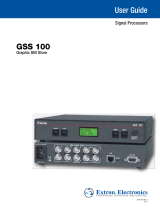
Extron GSS 100 User manual

Type
User manual
User Guide
GSS 100
Scalar & Signal Processors
Graphic Still Store
68-974-01 Rev. D
11 19
Safety Instructions
Safety Instructions • English
WARNING: This symbol, , when used on the product, is intended to
alert the user of the presence of uninsulated dangerous voltage within the
product’s enclosure that may present a risk of electric shock.
ATTENTION: This symbol, , when used on the product, is intended
to alert the user of important operating and maintenance (servicing)
instructions in the literature provided with the equipment.
For information on safety guidelines, regulatory compliances, EMI/EMF
compatibility, accessibility, and related topics, see the Extron Safety and
Regulatory Compliance Guide, part number 68-290-01, on the Extron
website,
www.extron.com.
Sicherheitsanweisungen • Deutsch
WARNUNG: Dieses Symbol auf dem Produkt soll den Benutzer darauf
aufmerksam machen, dass im Inneren des Gehäuses dieses Produktes
gefährliche Spannungen herrschen, die nicht isoliert sind und die einen
elektrischen Schlag verursachen können.
VORSICHT: Dieses Symbol auf dem Produkt soll dem Benutzer in
der im Lieferumfang enthaltenen Dokumentation besonders wichtige
Hinweise zur Bedienung und Wartung (Instandhaltung) geben.
Weitere Informationen über die Sicherheitsrichtlinien, Produkthandhabung,
EMI/EMF-Kompatibilität, Zugänglichkeit und verwandte Themen finden Sie in
den Extron-Richtlinien für Sicherheit und Handhabung (Artikelnummer
68-290-01) auf der Extron-Website, www.extron.com.
Instrucciones de seguridad • Español
ADVERTENCIA: Este símbolo, , cuando se utiliza en el producto,
avisa al usuario de la presencia de voltaje peligroso sin aislar dentro del
producto, lo que puede representar un riesgo de descarga eléctrica.
ATENCIÓN: Este símbolo, , cuando se utiliza en el producto, avisa
al usuario de la presencia de importantes instrucciones de uso y
mantenimiento recogidas en la documentación proporcionada con el
equipo.
Para obtener información sobre directrices de seguridad, cumplimiento
de normativas, compatibilidad electromagnética, accesibilidad y temas
relacionados, consulte la Guía de cumplimiento de normativas y seguridad
de Extron, referencia 68-290-01, en el sitio Web de Extron, www.extron.com.
Instructions de sécurité • Français
AVERTISSEMENT : Ce pictogramme, , lorsqu’il est utilisé sur le
produit, signale à l’utilisateur la présence à l’intérieur du boîtier du
produit d’une tension électrique dangereuse susceptible de provoquer
un choc électrique.
ATTENTION : Ce pictogramme, , lorsqu’il est utilisé sur le produit,
signale à l’utilisateur des instructions d’utilisation ou de maintenance
importantes qui se trouvent dans la documentation fournie avec le
matériel.
Pour en savoir plus sur les règles de sécurité, la conformité à la
réglementation, la compatibilité EMI/EMF, l’accessibilité, et autres sujets
connexes, lisez les informations de sécurité et de conformité Extron, réf.
68-290-01, sur le site Extron, www.extron.com.
Istruzioni di sicurezza • Italiano
AVVERTENZA: Il simbolo, , se usato sul prodotto, serve ad
avvertire l’utente della presenza di tensione non isolata pericolosa
all’interno del contenitore del prodotto che può costituire un rischio di
scosse elettriche.
ATTENTZIONE: Il simbolo, , se usato sul prodotto, serve ad avvertire
l’utente della presenza di importanti istruzioni di funzionamento e
manutenzione nella documentazione fornita con l’apparecchio.
Per informazioni su parametri di sicurezza, conformità alle normative,
compatibilità EMI/EMF, accessibilità e argomenti simili, fare riferimento
alla Guida alla conformità normativa e di sicurezza di Extron, cod. articolo
68-290-01, sul sito web di Extron, www.extron.com.
I
Copyright
© 2005-2019 Extron Electronics. All rights reserved. www.extron.com
Trademarks
All trademarks mentioned in this guide are the properties of their respective owners.
The following registered trademarks (
®
), registered service marks (
SM
), and trademarks (
TM
) are the property of RGBSystems, Inc. or
ExtronElectronics (see the current list of trademarks on the Terms of Use page at www.extron.com):
Registered Trademarks
(
®
)
Extron, Cable Cubby, ControlScript, CrossPoint, DTP, eBUS, EDID Manager, EDID Minder, Flat Field, FlexOS, Glitch Free. Global
Configurator, GlobalScripter, GlobalViewer, Hideaway, HyperLane, IPIntercom, IPLink, KeyMinder, LinkLicense, LockIt, MediaLink,
MediaPort, NetPA, PlenumVault, PoleVault, PowerCage, PURE3, Quantum, Show Me, SoundField, SpeedMount, SpeedSwitch,
StudioStation, SystemINTEGRATOR, TeamWork, TouchLink, V-Lock, VideoLounge, VN-Matrix, VoiceLift, WallVault, WindoWall, XTP,
XTPSystems, and ZipClip
Registered Service Mark
(SM)
: S3 Service Support Solutions
Trademarks
(
)
AAP, AFL (Accu-RATEFrameLock), ADSP(Advanced Digital Sync Processing), Auto-Image, AVEdge, CableCover, CDRS(ClassD
Ripple Suppression), Codec Connect, DDSP(Digital Display Sync Processing), DMI (DynamicMotionInterpolation), DriverConfigurator,
DSPConfigurator, DSVP(Digital Sync Validation Processing), eLink, EQIP, Everlast, FastBite, FOX, FOXBOX, IP Intercom HelpDesk,
MAAP, MicroDigital, Opti-Torque, PendantConnect, ProDSP, QS-FPC(QuickSwitch Front Panel Controller), RoomAgent, Scope-Trigger,
ShareLink, SIS, SimpleInstructionSet, Skew-Free, SpeedNav, Triple-Action Switching, True4K, Vector 4K , WebShare, XTRA, and
ZipCaddy
FCC Class A Notice
This equipment has been tested and found to comply with the limits for a Class A digital
device, pursuant to part15 of the FCC rules. The ClassA limits provide reasonable
protection against harmful interference when the equipment is operated in a commercial
environment. This equipment generates, uses, and can radiate radio frequency energy and,
if not installed and used in accordance with the instruction manual, may cause harmful
interference to radio communications. Operation of this equipment in a residential area is
likely to cause interference. This interference must be corrected at the expense of the user.
NOTE: For more information on safety guidelines, regulatory compliances, EMI/EMF
compatibility, accessibility, and related topics, see the Extron Safety and Regulatory
Compliance Guide on the Extron website.
Conventions Used in this Guide
Notifications
The following notifications are used in this guide:
ATTENTION:
Risk of property damage.
Risque de dommages matériels.
NOTE: A note draws attention to important information.
Software Commands
Commands are written in the fonts shown here:
^AR Merge Scene,,0p1 scene 1,1 ^B 51 ^W^C.0
[01]
R
0004
00300
00400
00800
00600
[02]
35
[17]
[03]
E
X! *X1&* X2)* X2#* X2! CE}
NOTE: For commands and examples of computer or device responses used in this
guide, the character “0” is the number zero and “O” is the capital letter “o.”
Computer responses and directory paths that do not have variables are written in the font
shown here:
Reply from 208.132.180.48: bytes=32 times=2ms TTL=32
C:\Program Files\Extron
Variables are written in slanted form as shown here:
ping xxx.xxx.xxx.xxx —t
SOH R Data STX Command ETB ETX
Selectable items, such as menu names, menu options, buttons, tabs, and field names are
written in the font shown here:
From the
File menu, select New.
Click the
OK button.
Specifications Availability
Product specifications are available on the Extron website, www.extron.com.
Extron Glossary of Terms
A glossary of terms is available at http://www.extron.com/technology/glossary.aspx.
Contents
Introduction ................................................1
About this Guide .................................................. 1
About the GSS 100 Graphic Still Store ................ 1
Features .............................................................. 2
Installation .................................................. 3
Mounting the GSS ............................................... 3
Rear Panel Connections ...................................... 3
Power Connection ........................................... 3
Signal Connections .......................................... 4
Remote Connections ....................................... 4
Reset Button ................................................... 5
Operation....................................................6
Front Panel Controls and Indicators ..................... 6
Front Panel Operations ........................................ 7
Power-on Indications ....................................... 7
Selecting an Image to Display .......................... 8
Muting the Video Output .................................. 8
Menu System Overview ................................... 9
Front Panel Security Lockout
(Executive Mode) .......................................... 15
Front Panel Absolute Reset............................ 15
Programming Guide ..................................16
Simple Instruction Set Control ........................... 16
Symbols ........................................................ 16
GSS-initiated (Unsolicited) Messages ............. 16
Host-to-GSS Instructions............................... 18
Error Responses ............................................ 18
Timeout ......................................................... 18
Using the Command and Response Tables ... 18
Command and Response Table for SIS
Commands ...................................................... 20
Command and Response Table for
IP-Specific SIS Commands .............................. 25
HTML Control and IPL File Manager ...........27
Configuring the Hardware .................................. 27
PC Configuration ........................................... 27
Initial Startup .................................................. 28
GSS Configuration ......................................... 28
Opening the Embedded Web Pages .................. 30
Status Tab ......................................................... 32
System Status Page ...................................... 32
Configuration Tab .............................................. 33
System Settings Page ................................... 33
Video Settings Page ...................................... 36
Passwords Page............................................ 37
Email Alerts Page ........................................... 37
Firmware Upgrade Page ................................ 38
File Management Tab ........................................ 40
File Management Page .................................. 40
Control Tab ........................................................ 41
Control Page ................................................. 41
Images Tab ........................................................ 42
Image Settings Page...................................... 42
Installing the IPL File Manager and Uploading
Images ............................................................. 44
Installing the IPL File Manager ........................ 44
Uploading Image Files.................................... 44
Special Characters ............................................ 46
Reference Information ...............................47
Mounting the Unit .............................................. 47
Tabletop Placement ....................................... 47
Rack Mounting .............................................. 47
Furniture Mounting......................................... 48
viiGSS 100 Graphic Still Store • Contents
GSS 100 Graphic Still Store • Contents viii
Introduction
This section introduces the Extron GSS 100 Graphic Still Store, including:
About this Guide
About the GSS 100 Graphic Still Store
Features
About this Guide
This manual contains installation and operating information for the Extron GSS 100 Graphic
Still Store.
NOTE: Throughout this guide, the unit is identified as either "GSS 100," the “GSS,” or
the “graphic still store.”
About the GSS 100 Graphic Still Store
The Extron GSS 100 (see figure 1) is a portable graphic still store with 16 MB of memory,
into which you can load up to 6 XGA (1024 x 768) bitmap images (BMP) or 32 or more
(depending on the compression rate) XGA JPG still images. The GSS can then output them
in an RGB video format. The GSS provides a pass-through RGB video input, in addition to
the stored images, and allows you to switch the output between the input and one of the
stored images. This allows you to display a still image of your own choosing, such as a logo,
text, or a landscape, during meeting breaks or while you load or make last minute edits to a
presentation on a laptop computer.
R
R
50/60 H
z
RS-23
2
LAN
RESET
G
G
B
B
H
H
V
V
100-
240V .1A MA
X
RG
B PASS-TH
RU
OUTPUT
Extron
GSS 100
Graphic Still Store
Multiple Images
(for recall during
presentations)
Projector
Graphics PC
Laptop
TCP/IP
Network
Figure 1. Typical GSS 100 Application
GSS 100 Graphic Still Store • Introduction 1
User-selected images, including the test patterns, can be uploaded to the GSS via its
Ethernet port using HTML pages built into the GSS. The pass-through RGB input and the
output are via female BNC connectors.
The GSS provides 16 MB of RAM for storage, providing room for up to 17 uploaded bitmap
images. The number of images that the GSS can accommodate depends on the resolution
of the images. Table 1 shows the number of BMP images that the GSS can accommodate,
based on several common resolutions.
Resolution 640x480 800x600 1024x768 1280x1024 1400x1050
Size 900 kB 1400 kB 2400 kB 4000 kB 4400 kB
Image space 17 11 6 4 3
Table 1. Approximate Image Space for BMP Files
NOTE: Because of the variable compression schemes for JPG images, there is no
reliable method to calculate the number of JPG images that the GSS can hold.
Progressive JPG images are not supported.
Bitmap (BMP) images must be formatted as 24-bit RGB.
The graphic still store is housed in a rack-mountable, 1U high, half rack-width metal
enclosure. The internal 100 VAC to 240 VAC, 50-60 Hz, 15-watt, power supply provides
worldwide power compatibility.
Features
16 MB of internal memory storage — Sufficient for 6 XGA resolution (1024 x 768)
BMP graphics, or 32 or more JPG images at XGA resolution, depending on the
compression rate.
Input pass-through mode
Cut or dissolve switch effect between stored images
Slide show effect automatically cycles through images.
Auto-switch mode — Automatically switches to the selected stored image or a slide
show when sync is lost on the pass-through input.
Rack and under-desk mountable
Worldwide internal power supply
GSS 100 Graphic Still Store • Introduction 2
Installation
This section details the installation of the GSS 100, including:
Mounting the GSS
Rear Panel Connections
Mounting the GSS
ATTENTION:
Installation and service must be performed by authorized personnel only.
L
’installation et l’entretien doivent être effectués uniquement par un technicien
qualifié.
Detailed mounting instructions can be found in Reference Information starting
on page47. The 1U high, half-rack width GSS 100 can be placed on a tabletop,
mounted on a rack shelf, (see Rack Mounting on page47) or mounted under or through
furniture (see Furniture Mounting on page48). Use the applicable optional hardware:
RSU 129 9.5-inch deep universal rack shelf kit
RSB 129 9.5-inch deep basic rack shelf
MBU 125 Under
-desk mount kit
MBD 129 Thr
ough-desk mount kit
Rear Panel Connections
All connectors are on the rear panel (see figure 2).
R
R
50/60 Hz
RS-232
LAN
RESET
G
G
B
B
H/HV
H/HV
V
V
100-240V .3A MAX
RGB PASS-THRU
OUTPUT
4 5
3 6
2
11
2
2
334
46655
Figure 2. GSS 100 Graphic Still Store Rear Panel
Power Connection
1
AC power connector — Plug a standard IEC power cord into this connector to connect
the GSS to a 100 VAC to 240 VAC, 50 or 60 Hz power source.
GSS 100 Graphic Still Store • Installation 3
Signal Connections
2
RGB PASS-THRU connectors — Connect a high resolution or computer input (VGA,
SVGA, XGA, SXGA, or UXGA) to these female BNC connectors.
3
OUTPUT connectors — Connect an RGB video display or other device to these
female BNC connectors (see figure 3 to connect the RGB video format for each
configuration).
RGBHV
R
RGBS
G B H/HV
V
R
G B H/HV V
Figure 3. Video Output Connection Format
NOTE: The still image output format (RGBHV or RGBS) must be configured
using the front panel controls or a Simple Instruction Set (SIS™) command (see
Programming Guide, beginning on page 1). The output format applies only to
the output of still images stored in the GSS; the RGB Pass-through video is output
exactly as it is input.
Remote Connections
Ethernet connection
4
LAN port Connect the GSS to a PC or to an Ethernet LAN, via this RJ-45 connector.
You can use the HTML pages embedded in the GSS to upload still images from the PC
to the GSS and to control the GSS. You can also use a PC to control the GSS with SIS
commands.
Link LED indicator — The green (link) LED indicates that the
Link
LED
Activity
LED
GSS 100 is properly connected to an Ethernet LAN. This LED should
light steadily.
Activity LED indicator — The yellow (activity) LED indicates
transmission of data packets on the RJ-45 connector. This LED should
flicker as the GSS 100 communicates.
Cabling
It is vital that your Ethernet cables be the correct cable type and that they be correctly
terminated with the proper connector pinout. Ethernet links use Category (CAT) 3, 5e, or 6,
unshielded twisted pair (UTP) or shielded twisted pair (STP) cables, terminated with RJ-45
connectors. Ethernet cables are limited to a length of 328 feet (100 m).
NOTES:
Do not use standard telephone cables. Telephone cables do not support Ethernet
or Fast Ethernet.
Do not stretch or bend cables. Transmission errors can occur.
The cable used depends on your network speed. The GSS 100 supports both
10 Mbps (10Base-T — Ethernet) and 100 Mbps (100Base-T — Fast Ethernet), half-duplex
and full-duplex Ethernet connections.
10Base-T Ethernet requires CAT 3 UTP or STP cable at minimum.
100Base-T Fast Ethernet requires CAT 5e UTP or STP cable at minimum.
GSS 100 Graphic Still Store • Installation 4
RJ-45 connector wiring
The Ethernet cable can be terminated as a straight-through cable or a crossover cable and
must be properly terminated for your application (see figure 4).
Crossover cable — Direct connection between the computer and the GSS 100
Patch (straight) cable — Connection of the GSS 100 to an Ethernet LAN
A cable that is wired as T568A at one end
and T568B at the other (Tx and Rx pairs
reversed) is a "crossover" cable.
A cable that is wired the same at both ends is
called a "straight-through" cable, because
no pin/pair assignments are swapped.
12345678
RJ-45
Connector
Inser
t Twisted
Pair Wires
Pins:
Crossover Cable Straight-through Cable
Pin
1
2
3
4
5
6
7
8
Wire color
White-green
Green
White-orange
Blue
White-blue
Orange
White-brown
Brown
Wire color
T568A T568B
End 1 End 2 End 1 End 2
White-orange
Orange
White-green
Blue
White-blue
Green
White-brown
Brown
Pin
1
2
3
4
5
6
7
8
Wire color
White-orange
White-green
Blue
White-blue
White-brown
Brown
Wire color
T568BT568B
White-orange
OrangeOrange
White-green
Blue
White-blue
GreenGreen
White-brown
Brown
Figure 4. RJ-45 Connector and Pinout Tables
Serial connection
5
RS-232 port — Connect a computer or control system to this 9-pin D connector to
allow remote control using the SIS commands (see figure 5 and the Programming
Guide section).
5
1
9
6
RS-232 FunctionPin
1
2
3
4
5
6
7
8
9
Tx
Rx
Gnd
Not used
Transmit data
Receive data
Not used
Signal ground
Not used
Not used
Not used
Not used
RS-232
Figure 5. RS-232 Connector Pinout
Reset Button
6
RESET button — The Reset button initiates three levels of reset to the GSS. Press
and hold the button while the GSS is running or while you power up the GSS for
different reset levels.
Events (mode 3) reset — Hold the Reset button for approximately 3 seconds (the
Reset LED blinks once), then release it and push it again for a moment to toggle
events monitoring on and off.
IP settings (mode 4) reset — Hold the Reset button for approximately 6 seconds
(the Reset LED blinks twice), then release it and push it again for a moment to
reset the IP functions of the GSS.
Absolute (mode 5) reset — Hold the Reset button for approximately 9 seconds
(the Reset LED blinks three times), then release it and push it again for a moment
to restore the GSS to the default factory conditions.
NOTE: The absolute (mode 5) reset clears all image files, IP settings, and user
settings and resets the graphic still store to the factory default.
GSS 100 Graphic Still Store • Installation 5
Operation
This section describes the front panel operation of the GSS 100, including:
Fr
ont Panel Controls and Indicators
Fr
ont Panel Operations
Front Panel Controls and Indicators
Figure 6 shows the controls and indicators on the front panel of the GSS 100 (see Front
Panel Operations on the next page for details on using these controls and indicators).
GSS 100
ADJUST/
SELECT
IMAGE
TAKE
MENU
NEXT
1 2 43 65
11
3
3
4
4
6
6
5
5
2
2
Figure 6. GSS 100 Front Panel
1
IMAGE button — Press the IMAGE button to activate the menu on the LCD display
(
3
) that allows you to select between the pass-through input and one of the stored
images.
2
TAKE button — Press the TAKE button to select either the pass-through input or one
of the stored images.
3
LCD display — The 8-column by 2-line LCD screen displays output and configuration
menus and status information.
4
MENU button — Press the MENU button to enter and move through the main menu
system in the GSS.
5
NEXT button — Press the NEXT button to step through the submenus in the GSS
menu system.
6
ADJUST/SELECT knob — Rotate the ADJUST/SELECT knob to change settings
when it is used in conjunction with the IMAGE and TAKE buttons or the MENU and NEXT
buttons.
GSS 100 Graphic Still Store • Operation 6
Front Panel Operations
Plug in all system components and turn on the input device (such as a desktop or laptop
computers) and the output monitor. Use the LAN port to upload one or more still images
to the GSS. Select either the pass-through input or one of the stored still images to output
(see Selecting an Image to Display on the next page). The image should appear on the
monitor connected to the output.
Power-on Indications
Power is applied when the power cord is connected between the GSS and an AC source.
When AC power is applied, the GSS performs a self-test that shows the model name and
the firmware version in the LCD display. After approximately 15 seconds, the LCD diplays
its default cycle, alternating among four displays that show the model name, the currently
displayed image (the pass-through input or the file name of one of the previously loaded
images), the output resolution (of a stored image only; the pass-through input is output
exactly as it is input), and the IP address of the unit (see figure 7).
The current settings are saved in nonvolatile memory. When power is applied, the latest
configuration is retrieved.
NOTE: On figure 7 and all other flowcharts in this chapter, dashed lines indicate screen
changes that are the result of a timeout function.
Default Cycle
3 sec.
3 sec.
Power
on
3 sec.
3 sec.
or
3 sec.
Extron
GSS 100
Extron
GSS 100
1024 x
768 @72
I192.168
P255.255
RGB
PASSTHRU
or
Viewing
Image
Viewing
PassThru
Version
n.nn
3 sec.
Figure 7. LCD Power-on Displays and Default Display Cycle
NOTE: If the displayed file name is too large (more than eight characters, including the
file extension) for the LCD, the LCD shifts the file name:
Viewing
lename.jp
Viewing
Largefil
Viewing
ename.jpg
GSS 100 Graphic Still Store • Operation 7
Selecting an Image to Display
NOTES:
The only valid file formats for uploaded image files are BMP and JPG.
V
alid file names are up to 240 alphanumeric characters with no spaces.
Pr
ogressive JPG images are not supported.
Bitmap (BMP) images must be formatted as 24-bit RGB.
1080i and 1080p files need to be master
ed at a resolution of 1440 x 1080
instead of the expected 1920 x 1080.
Select an image to display as follows:
1.
Pr
ess and release the IMAGE button (see figure 8).
Select
PassThru
Loading
Image
Select
Filename
IMAGE
Step 1 Step 2 Step 3
TAKE
ADJUST/
SELECT
or
Default
Cycle
Figure 8. Selecting an Image
2. Rotate the ADJUST/SELECT knob to select either PassThru or one of the previously
loaded images by file name.
3. Press and release the Take button. The LCD shows Loading Image and then returns
to the default display cycle once the image is loaded.
Muting the Video Output
To toggle the video output mute on and off, press and hold the TAKE button for
approximately 3 seconds (see figure 9). When the video output is muted (video is not
output), an asterisk (*) appears and blinks in the LCD default display cycle, in either the
output resolution display or the RGB pass-through display. When the video output is
unmuted (video is output), the asterisk is not present.
Muting the
Output
Press and
hold.
Release the
button.
Release the
button.
3
Sec.
TAKE
Asterisk (*)
blinks to indicate
the output is muted.
Default
Cycle
1024 x
768 @72
RGB
PASSTHRU
*
*
Unmuting the
Output
Press and
hold.
3
Sec.
TAKE
Asterisk (*)
goes out to indicate
the output is unmuted.
Default
Cycle
1024 x
768 @72
RGB
PASSTHRU
Figure 9. Muting and Unmuting the Output
GSS 100 Graphic Still Store • Operation 8
Menu System Overview
Figure 10 shows a flowchart of the main menus in the menu system.
Power
on
3 sec.
Menu
Default
Cycle
Menu
10 sec.
3 sec.
Menu Menu
Menu
Next
Extron
GSS 100
Output
Config
Menu
Slide
Show
Advanced
Menu
Exit
Menu
Switch
Effect
10 sec.
Version
n.nn
10 sec. 10 sec.
10 sec.
Figure 10. Menu System Flowchart
MENU button — Press the MENU button to activate the menu system and to scroll through
the five main menus.
NEXT button — Press the NEXT button to move between the submenus of a selected main
menu, to activate one for viewing or configuration, and to save a selection.
ADJUST/SELECT knob — When in a submenu, rotate the ADJUST/SELECT knob to scroll
through the submenu options and select a setting. See the flowcharts in this section and
specific subsections for explanations of knob adjustments.
NOTES:
To return to the default cycle, let the GSS remain idle for 30 seconds until the
selected screen times out, or press the MENU button until the Exit Menu appears,
then press the NEXT button.
From any menu or submenu, after 30 seconds of inactivity, the GSS saves all
adjustment settings and times out to the default LCD display cycle.
The GSS saves settings to its non-volatile memory every 3 minutes. Ensure that you
wait at least 3 minutes after making any changes or those changes may be lost.
Switch Effect menu
Figure 11 is a flowchart that shows an overview of the Switch Effect menu and the
available settings.
Menu Menu 10 sec. 10 sec.
Power
on
Menu
Default
Cycle
Next
Switch
Effect
Next Next
Menu
Menu
Menu
Menu
Menu
10
sec.
10
sec.
Output
Config
Slide
Show
Advanced
Menu
Exit
Menu
10
sec.
10
sec.
10
sec.
Effect
Cut
Duration
0.0 Secs
Output transition
• Cut • Dissolve
Dissolve duration
0.0 to 5.0 seconds in
0.1 second increments.
Figure 11. Switch Effect Menu Flowchart
GSS 100 Graphic Still Store • Operation 9
Effect submenu
Rotate the ADJUST/SELECT knob while in the Effect submenu to cut (immediate switch)
and dissolve (the image dissolves from old to new). Cut is the default selection.
Duration submenu
Rotate the ADJUST/SELECT knob while in the Duration submenu to select the duration for
the dissolve effect (if it is selected), between 0.0 and 5.0 seconds in 0.1 second increments.
The default duration is 1.0 seconds.
Output Configuration menu
Figure 12 is a flowchart that shows an overview of the Output Configuration menu and
the available settings.
10 sec. 10 sec.
Power
on
Menu
Default
Cycle
Next
Next
Next
Menu
Menu
Menu
Menu
Menu
10
sec.
10
sec.
Output
Config
Slide
Show
Advanced
Menu
Exit
Menu
10
sec.
10
sec.
10
sec.
1024 x
768 @60
Sync
RGBHV
Next
Output sync format
• RGBHV • RGBS
Resolution
See the table
on page 12.
Switch
Effect
10 sec. 10 sec.
Cut duration
0.0 to 5.0 seconds in
0.1 second increments.
Sync polarity
• H-/V- • H+/V-
• H-/V+ • H+/V+
Next
Menu Menu
Menu Menu
RGB Dly
0.0 Sec
H Pol V
Neg Neg
Figure 12. Output Configuration Submenu
NOTE: The Output Configuration menu settings apply only to the output of still
images stored in the GSS; the RGB Pass-through video is output exactly as it is input.
GSS 100 Graphic Still Store • Operation 10
Resolution submenu
Rotate the ADJUST/SELECT knob while in the Resolution submenu to select the resolution
of the stored image output. 1024 x 768 at 60 Hz is the default resolution.
NOTE: To view an uncropped full screen image at 1080p or 1080i, the image resolution
must be 1440 x 1080.
Resolution 50
Hz
60
Hz
72
Hz
96
Hz
100
Hz
120
Hz
640 x 480
800 x 600
852 x 480
1024 x 768
1024 x 852
1024 x 1024
1280 x 768
1280 x 800
1280 x 1024
1360 x 765
1365 x 768
1366 x 768
1365 x 1024
1400 x 1050
1440 x 900
480p
576p
720p
1080i
1080p
Sync format submenu
Rotate the ADJUST/SELECT knob while in the Sync format submenu to select the sync
format for the still image output. RGBHV is the default selection.
Sync polarity submenu
Rotate the ADJUST/SELECT knob while in the Sync polarity submenu to select the sync
polarity (positive and negative) for the still image output. Horizontal and vertical negative
sync are the default selection.
RGB Delay submenu
The GSS can briefly blank the RGB (video) output while it switches between the stored
image and the pass-through image. This allows the change in display to appear without a
glitch. RGB delay is also known as Triple-Action Switching or video mute switching.
Rotate the ADJUST/SELECT knob while in the RGB Delay submenu to set the delay between
0 and 5 seconds, in 0.1-second increments. No delay (0.0 seconds) is the default setting.
GSS 100 Graphic Still Store • Operation 11
Slide Show menu
Figure 13 is a flowchart that shows an overview of the Slide Show menu and the available
settings.
10 sec.10 sec.
Power
on
Menu
Default
Cycle
Next
Next Next
Menu
Menu
Menu
Menu
Menu
10
sec.
10
sec.
Advanced
Menu
Exit
Menu
10
sec.
10
sec.
10
sec.
Duration
030 Secs
PassThru
Disabled
Pass-Thru Input
• Disabled
• Enabled
Duration
0 to 300 seconds in
1 second increments
Switch
Effect
Slide
Show
Output
Config
Menu Menu
Figure 13. Slide Show Submenu Flowchart
Duration submenu
Rotate the ADJUST/SELECT knob while in the Duration submenu to set the duration
of each displayed image in the slide show between 0 and 300 seconds, in 1-second
increments. The default duration is 30 seconds.
NOTE: The actual time that an image is displayed may vary, based on the decoding
time of the next image in the slide show.
Pass-Thru submenu
Rotate the ADJUST/SELECT knob while in the Pass-Thru submenu to enable or disable
the inclusion of the pass-through input as part of the slide show. The pass-through input is
disabled from being part of the slide show by default.
GSS 100 Graphic Still Store • Operation 12
  • Page 1 1
  • Page 2 2
  • Page 3 3
  • Page 4 4
  • Page 5 5
  • Page 6 6
  • Page 7 7
  • Page 8 8
  • Page 9 9
  • Page 10 10
  • Page 11 11
  • Page 12 12
  • Page 13 13
  • Page 14 14
  • Page 15 15
  • Page 16 16
  • Page 17 17
  • Page 18 18
  • Page 19 19
  • Page 20 20
  • Page 21 21
  • Page 22 22
  • Page 23 23
  • Page 24 24
  • Page 25 25
  • Page 26 26
  • Page 27 27
  • Page 28 28
  • Page 29 29
  • Page 30 30
  • Page 31 31
  • Page 32 32
  • Page 33 33
  • Page 34 34
  • Page 35 35
  • Page 36 36
  • Page 37 37
  • Page 38 38
  • Page 39 39
  • Page 40 40
  • Page 41 41
  • Page 42 42
  • Page 43 43
  • Page 44 44
  • Page 45 45
  • Page 46 46
  • Page 47 47
  • Page 48 48
  • Page 49 49
  • Page 50 50
  • Page 51 51
  • Page 52 52
  • Page 53 53
  • Page 54 54
  • Page 55 55
  • Page 56 56
  • Page 57 57

Extron GSS 100 User manual

Type
User manual

Ask a question and I''ll find the answer in the document

Finding information in a document is now easier with AI