
PROFINET
Communication Protocol of PUE HX5.EX Indicator
SOFTWARE MANUAL
ITKP-02-02-08-18-EN

2
AUGUST 2018

3
CONTENTS
1. DATA STRUCTURE ......................................................................................................................................4
1.1. Input Address...........................................................................................................................................4
1.2. Output Address........................................................................................................................................6
2. CONFIGURATION OF PROFINET MODULE IN TIA PORTAL V14..............................................................9
2.1. GSD Import..............................................................................................................................................9
2.2. Module Configuration.............................................................................................................................11
3. PLC SOFTWARE SAMPLE.........................................................................................................................16

4
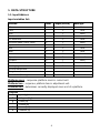
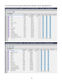
1. DATA STRUCTURE
1.1. Input Address
Input variables list:
Variable Offset Length [WORD] Data type
Mass 0 2 float
Tare 4 2 float
Unit 8 1 word
Platform status 10 1 word
LO threshold 12 2 float
Process status (Stop, Start) 16 1 word
Inputs status 66 1 word
Min 68 2 float
Max 72 2 float
Lot number 84 2 dword
Operator 88 1 word
Product 90 1 word
Customer 92 1 word
Packaging 94 1 word
Source warehouse - - -
Target warehouse - - -
Formulation/Dosing 100 1 word
Platform mass – response: platform mass in current unit.
Platform tare – response: platform tare in adjustment unit.
Platform unit – determines currently displayed mass unit of a platform.
Unit bits
0
- gram [g]
1
- kilogram [kg]
2
- carat [ct]
3
- pound [lb]
4
- ounce [oz]
5
- Newton [N]

5
Example:
bit No.
B5 B4 B3 B2 B1 B0
value 0 0 0 0 1 0
The unit of the weighing instrument is kilogram [kg].
Platform status – determines status of a weighing platform.
Status bits
0
- measurement correct (weighing instrument does not report an error)
1
- stable measurement
2
- weighing instrument indicates zero
3
- weighing instrument is tared
4
- weighing instrument is in II weighing range
5
- weighing instrument is in III weighing range
6
- weighing instrument reports NULL error
7
- weighing instrument reports LH error
8
- weighing instrument reports FULL error
Example:
bit No.
B8 B7 B6 B5 B4 B3 B2 B1 B0
value 0 0 0 0 1 0 0 1 1
The weighing instrument does not report error, stable measurement in II
weighing range.
LO threshold
– response: LO threshold value of a platform in adjustment unit.
Process status – determines process status:
bit No.
Decimal value Process status
B1 B0
0
process disabled 0 0
1
process start 0 1
2
process stop 1 0
3
process complete 1 1
Inputs status – response: status of set inputs:
Input No. 12 11 10 9 8 7 6 5 4 3 2 1
OFF 0 0 0 0 0 0 0 0 0 0 0 0
ON 1 1 1 1 1 1 1 1 1 1 1 1

6
Example:
Mask of set 2 and 4 inputs: 0000 0000 0000 1010
MIN
– response: MIN threshold value (in the current unit selected for active
working mode).
MAX – response: MAX threshold value (in the current unit selected for active
working mode).
Lot number – response: lot number.
Operator – response: code of logged in operator.
Product – response: code of selected product.
Customer – response: code of selected customer.
Packaging – response: code of selected packaging.
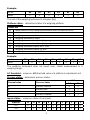
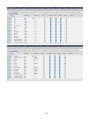
1.2. Output Address
Input variables list:
Variable Offset Length [WORD] Data type
Command 0 1 word
Command with parameter 2 1 word
Platform 4 1 word
Tare 6 2 float
LO threshold 10 2 float
Outputs status 14 1 word
Min 16 2 float
Max 20 2 float
Lot number 32 2 dword
Operator 36 1 word
Product 38 1 word
Customer 40 1 word
Packaging 42 1 word
Source warehouse - - -
Target warehouse - - -
Formulation/Dosing 48 1 word

7
Basic command – setting respective value performs the task in accordance
with the table:
Bit No. Command
0 Zero the platform
1 Tare the platform
2 Delete statistics
3 Save/Print
4 Start
5 Stop (error)
Example:
0000 0000 0010 0000 – process start.
Complex command – setting respective value performs the task in
accordance with the table:
Decimal value Command
0 Setting the tare value for given platform
1 Setting LO threshold value for given platform
2 Setting lot number
3 Setting outputs status
4 Operator selection
5 Product selection
6 Packaging selection
7 Setting MIN threshold value
8 Customer selection
9 Source warehouse selection
10 Target warehouse selection
11 Dosing selection
12 Setting MAX threshold value
Complex command requires setting address of respective
parameter (from 2 to 24 – refer to: 'Complex command
parameters' table).
Example:
0000 0000 0000 0010 – command sets LO threshold to the value set in LO
parameter (address 5 – refer to: 'Complex command parameters' table).

8
Platform – complex command parameter: weighing platform number.
Tare – complex command parameter: tare value (in adjustment unit).
LO threshold – complex command parameter: LO threshold value
(in adjustment unit).
Outputs status – complex command parameter: determines status
of weighing indicator outputs.
Output No. 12 11 10 9 8 7 6 5 4 3 2 1
OFF 0 0 0 0 0 0 0 0 0 0 0 0
ON 1 1 1 1 1 1 1 1 1 1 1 1
Example:
Mask of active 2 and 4 outputs: 0000 0000 0000 1010
MIN – complex command parameter: MIN threshold value (in the current unit
selected for active working mode).
MAX – complex command parameter: MAX threshold value (in the current unit
selected for active working mode).
Lot number – complex command parameter: lot number.
Operator – complex command parameter: code of logged in operator.
Product – complex command parameter: code of selected product.
Customer – complex command parameter: code of selected customer.
Packaging – complex command parameter: code of selected packaging.
A command or a command with parameter is executed once
when its bit setting is detected. If the command with the same
bit is to be executed again, zero the bit.
Example:
Command
Taring 0000 0000 0000 0010
Command bits zeroing 0000 0000 0000 0000
Taring 0000 0000 0000 0010

9
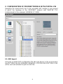
2. CONFIGURATION OF PROFINET MODULE IN TIA PORTAL V14
Operating the environment has to be preceded with creating a new project
in which the topology of the PROFINET network with MASTER PLC
is determined (in this example: SIEMENS S7-1200).
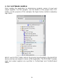
2.1. GSD Import
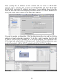
Using the included GSD configuration file add new device to the environment.
Use OPTIONS tab first, MANAGE GENERAL STATION DESCRIPTION FILES
(GSD) next and indicate the path to GSD file.

10
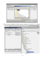
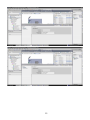
Upon successful adding of the file using list of devices, find ABIC-PRT module:

11
You can now create a network consisting of one MASTER PLC and added
SLAVE module:
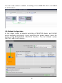
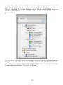
2.2. Module Configuration
At this stage, create a network consisting of MASTER device and SLAVE
device (weighing instrument). Upon connecting the power supply, search for
device using ACCESSIBLE DEVICES function. The list should contain
MASTER and SLAVE devices:

12
Next, specify the IP address of the module and its name in PROFINET
network. Upon selecting the module in PROPERTIES tab, find PROFINET
INTERFACE and enter IP address and name. Those settings have to be the
same as the ones set in the weighing instrument menu. IP SLAVE address has
to be part of the same subnet as the MASTER address.
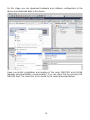
Proceed to module configuration. Start by determining the size and the starting
address of input and output registers. To do this, select modules from the list
of INPUT and OUTPUT modules as in the picture below. The maximum size
of the input and output data is 116 bytes each. Default starting addresses were
used in the project - 68 for INPUT module and 64 for OUTPUT module:

13

14
On this stage you can download hardware and software configuration to the
device and download data to the device.
Upon successful compilation and loading of the code, MASTER and SLAVE
modules should establish communication. You can check this by pressing GO
ONLINE field. The result has to be similar to the result presented below.

15
The next step will be to create program code.

16
3. PLC SOFTWARE SAMPLE
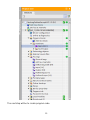
Start creating the application by determining symbolic names of input and
output registers. For this purpose, use the branch of the project tree: PLC
TAGS. For the purpose of this example, the figure below contains exemplary
tags tables:
INPUT and OUTPUT tables refer to the physical inputs/outputs of the MASTER
device and are not relevant in terms of this application. The PROFINET module
input and output registers are specified in ProfinetInput and ProfinetOutput
tables.

17
The pictures below present determined symbolic names and addresses:

18
In order to avoid working directly on module physical inputs/outputs, create
data blocks containing the representations of those registers and create
function 'rewriting' the values between them. Create HARDWARE group in
PROGRAM BLOCKS branch and determine data blocks in the same way as
presented below:
HD_OUTPUT and HD_INPUT blocks refer to physical MASTER inputs/outputs
and are not relevant in terms of this project. HD_ProfinetOutput and
HD_ProfinetInput blocks refer to the PROFINET module input/output registers
on a weighing instrument. They look as follows:

19

20
The functions that rewrite values between physical inputs/outputs of the
module may look like this:
Page is loading ...
Page is loading ...
-
 1
1
-
 2
2
-
 3
3
-
 4
4
-
 5
5
-
 6
6
-
 7
7
-
 8
8
-
 9
9
-
 10
10
-
 11
11
-
 12
12
-
 13
13
-
 14
14
-
 15
15
-
 16
16
-
 17
17
-
 18
18
-
 19
19
-
 20
20
-
 21
21
-
 22
22


RADWAG HX5.EX-1.4P2.2000.C1 User manual
- Type
- User manual
- This manual is also suitable for
Ask a question and I''ll find the answer in the document
Finding information in a document is now easier with AI
Related papers
-
RADWAG HY10.120.HRP User manual
-
RADWAG HY10.120.HRP User manual
-
RADWAG HX5.EX-1.4N.300.H1 User manual
-
RADWAG HX7.30.H3 User manual
-
RADWAG HY10.120.HRP User manual
-
-
RADWAG HY10.120.HRP User manual
-
RADWAG HY10.120.HRP User manual
-
-
RADWAG C32.6.F1.K User manual
Other documents
-
Flintec FT-10Fill Series Technical Manual
-
 BAYKON MX08 Technical Manual
-
Eurotherm EPower Controller Owner's manual
-
Mettler Toledo IND570 PLC Operating instructions
-
Hardy HI 4050 User manual
-
-
-
-
-
 RayTek RAYMI310LTF Owner's manual

