Page is loading ...

Original Instructions
Installation, Operation
&Maintenance Manual
Saf-T-Vise STV-HP1
Insertable Tool Holders
S-CM-IOM-00506-1 03-19

2 Sentry Equipment Corp
Do not install, maintain, or operate this equipment without reading, understanding, and following the
appropriate Sentry Equipment Corp instructions. Otherwise, injury, damage, or both may result.
Copyright
© 2019 by Sentry Equipment Corp. All rights reserved. All product and company names are property of their respective
owners. This document contains proprietary information. No part of this document may be photocopied or reproduced
without the prior written consent of Sentry Equipment Corp.
Limit of Liability
Sentry Equipment Corp, its employees, agents, and the authors and contributors to this document speci cally disclaim
all liabilities and warranties, express or implied (including warranties of merchantability and tness for a particular
purpose), for the accuracy, currency, completeness, and/or reliability of the information contained herein and/or for the
tness for any particular use and/or for the performance of any material and/or equipment selected in whole or part
with the user of/or in reliance upon information contained herein. Selection of materials and/or equipment is at the
sole risk of the user of this publication.
Note
The information contained in this document is subject to change without notice.

Saf-T-Vise STV-HP1 3
Table of Contents
Safety Information .........................................4
General Safety Precautions .................................5
General Description ........................................6
Specications ..............................................6
Saf-T-Vise SVT-HP1 Insertable Tool Holder Specications ..............6
Installation and Operation ..................................6
Maintenance ...............................................7
Inspecting the Safety Cap ............................................7
Prepping the Tool Holder for Reinstallation ...........................7
Cleaning the Rod/Probe Shaft ........................................7
Changing a Rod/Shaft and Replacing a Seal ..........................8
Changing a Coupon/Checking Probe End ............................10
Troubleshooting ...........................................11
Leaks ................................................................11
Locking Collet .......................................................12
Standard Warranty .........................................12
Customer Support ..........................................13

4 Sentry Equipment Corp
Safety Information
Please read the entire manual before attempting to unpack, set up, or operate this product. Pay careful attention to all
Warnings, Cautions, and Notes. Failure to do so could result in serious personal injury and/or equipment damage.
Use of Hazard Information
If multiple hazards exist, the signal word corresponding to the greatest hazard shall be used.
De nitions
DANGER indicates a hazardous situation which, if not
avoided, will result in death or serious injury.
WARNING indicates a hazardous situation which, if not
avoided, could result in death or serious injury.
CAUTION, used with the safety alert symbol, indicates a
hazardous situation which, if not avoided, could result in
minor or moderate injury.
NOTICE is used to address practices not related to personal
injury.
 NOTE
Information that requires special emphasis.
 TIP
Alternate techniques or clarifying information.
SHALL:
This word is understood to be mandatory.
SHOULD:
This word is understood to be advisory.

Saf-T-Vise STV-HP1 5
General Safety Precautions
Product Selection, Installation, and Use
Improper selection, installation, or use can cause personal injury or property damage. It is solely the responsibility of users,
through their own analysis and testing, to select products suitable for their speci c application requirements, ensure they are
properly maintained, and limit their use to their intended purpose.
Follow proper local, state, and federal regulations for proper installation and operational requirements.
Always use caution and common sense when working with any chemical. Read the product label and Material Safety Data
Sheets (MSDS) carefully and follow the instructions exactly.
Potential Equipment Hazards
Hot surfaces! This equipment may have very hot surfaces. If an operator contacts a hot surface, injury may occur. Use
protective clothing to prevent injury. If other equipment comes in contact with a hot surface, damage to the equipment may
occur. Ensure the area around this equipment is kept clear to prevent damage from occurring.
High pressures! This equipment may contain uids at very high pressures. Prior to installing, removing or maintaining this
equipment, ensure that the equipment is isolated from all connecting piping, the equipment is depressurized, the contents
have been drained, and the equipment is cool.

6 Sentry Equipment Corp
General Description
The Sentry® Saf-T-Vise SVT-HP1 insertable tool holders are
multi-functional tools that can be equipped to monitor
pipeline corrosion, inject chemical into the process, or
sample the pipeline medium. The holders are engineered
to specic site applications with a variety of materials and
connection styles and sizes. Design pressure and temperature
requirements determine the model series and sealing
technology of the holder.
The holders are designed with a patented locking collet which
secures the rod/shaft within the process stream until released
by the operator. A process bleeder valve is standard on holders
to allow depressurization of the holder after closure of the
process isolation valve. The ability to fully retract the rod/shaft
out of the pipeline while under pressure allows for pigging
without bringing the line down.
The standard Saf-T-Vise SVT-HP1 models require the use of an
insertion tool.
Specications
Saf-T-Vise SVT-HP1 Insertable Tool
Holder Specications
Maximum allowable operating pressure (MAP) of 5,000psi
at 100°F (344.7 bar at 38°C). NOTE: Flanged units have a
MAP based on the class of ange used for process line connection and can be rated to a lower MAP.
The Teon® seal has a maximum process temperature of 450°F (232.2°C).
The graphoil seal has a maximum process temperature of 1000°F (537.8°C).
Holder Type: Corrosion Coupon, Atomizer, Sample or Injection Quill.
316/316L SS is the standard material for process wetted components.
Connection Style: Flanged or NPT Threaded connection.
Standard NPT Connection Sizes: 1/2", 3/4", 1", 1-1/2", or 2".
Flange Connection Sizes: Customer specied. (In anged units, holder is threaded and welded to ange.)
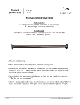
Installation and Operation
The Saf-T-Vise SVT-HP1 tool holders attach to a pipeline isolation valve by means of either a anged or NPT threaded
connection. A holder is installed or removed during the operation and maintenance of the equipment as detailed in
the Saf-T-Vise STV-T Series Insertion Tools manual.
Upper body
assembly
Lower body
assembly
Upper body
set screw
Bleeder
valve
NPT pipeline
connection
Collet
lock bolt
Safety cap
Indicator
button
Welded stop
Rod/shaft
Safety cap
NPT threads

Saf-T-Vise STV-HP1 7
Maintenance
 NOTE
All maintenance procedures assume the Saf-T-Vise SVT-HP1 insertable tool holder has been properly removed from the line.
See the Saf-T-Vise STV-T Series Insertion Tools manual for instructions.
Inspecting the Safety Cap
Remove safety cap from holder and ensure the red indicator is still in good condition.
If the indicator is faded, brittle, or missing, return the cap to the factory for indicator repair.
Prepping the Tool Holder for Reinstallation
After each use the tool holder threads should be checked and cleaned.
Tools needed
Clean rag
Pick or small screwdriver
Teon tape or paste
Anti-seize lubricant
1. Use a small pick or screwdriver to remove Teon tape from the threads of the holder and the isolation valve
connection threads.
2. After tape and debris are removed, wipe down the threads with a clean rag.
3. Reapply Teon tape and anti-seize lubricant to the holder threads.
Cleaning the Rod/Probe Shaft
The rod/probe shaft should be cleaned each time the tool holder is removed from the line. This helps prevent buildup
on the rod/shaft and damage to the seal.
Tools needed
Clean rag
Cleaner/solvent
320 grit sand paper or other ner grit paper
Medium crescent wrench
Molykote 55 lubricant or other ne viscosity lubricant
1. Remove the holder from the line.
2. Loosen the locking collet bolt and slide the rod/shaft to the fully inserted position (until the stop hits the top of the
body). Leave the locking collet loose so the rod/shaft can be spun inside the body.
3. Clean the exposed rod/shaft with 320 grit or ner sand paper using a rotational motion.
4. When the exposed rod/shaft is cleaned of external debris, wipe the rod/shaft with a clean rag and solvent to remove
any leftover debris.
5. Slide the rod/shaft to the fully retracted position and repeat the steps above to clean the remaining rod/shaft.
6. When the rod/shaft is thoroughly clean, wipe the rod/shaft with Molykote 55 lubricant or other ne viscosity
lubricant.

8 Sentry Equipment Corp
Changing a Rod/Shaft and Replacing a Seal
Tools needed
Medium crescent wrench
Permanent marker
¼" NPT nipple 2"–4" (5–10 cm) in length (for atomizers or quills only)
Hex key set
Small pick or screwdriver
Clean rag
Seal Installation Tool (for Teon seals only)
– P/N 2-07815E for 3/8" OD rod/shaft
– P/N 2-07815F for ¼" OD rod
New seal for holder (Teon or graphoil as needed)
Molykote 55 lubricant or other ne viscosity lubricant
Anti-seize lubricant
320 grit or ner sandpaper
Cleaner/solvent
1. Remove the rod/shaft.
a. With the holder removed from the line, loosen the locking collet and slide the rod/shaft to the fully inserted
position, leaving 1" (2.5 cm) between the top of the holder and the adapter lock nut.
b. Tighten the locking collet bolt to 35 ft-lb (47.45 Nm).
c. Remove adapter.
Coupon holder only:
– If using a at coupon, use a permanent marker to mark the rod to show where the orientation arrow points
on the shaft (reference the arrow at the top of the shaft).
– Use a medium crescent wrench to loosen the adapter lock nut.
– Remove both the adapter and the lock nut.
Atomizer shaft or quill shaft:
– With a permanent marker, mark the rod to show where the orientation arrow points on the shaft (reference
the arrow at the top of the shaft).
– If uid inlet does not have wrench ats, use a ¼" NPT nipple threaded into the uid inlet adapter to remove
the adapter from the shaft. If the adapter has a multi-port valve, you can use it to aid in removal.
d. Loosen the collet and slide the shaft out of the body of the holder.
2. Separate the upper and lower body of the holder
a. Use a hex key to loosen (but not completely remove) the small set screw on the upper body.
Make sure the set screw is loose. Failure to loosen the set screw can cause permanent damage to the holder.
b. With the set screw loose, remove the upper body.
 NOTE
If the upper body is dicult to remove, stop immediately and make sure that the set screw is loose.
3. Replace the seal.
a. With the upper body removed, use a pick or small screwdriver to gently pick out the old seal.
b. Clean the seal body of the holder with a clean rag.

Saf-T-Vise STV-HP1 9
c. Insert new seal:
For Teon seal:
– Place the new Teon seal onto the seal insertion tool with the seal opening facing away from the handle.
– Lubricate the open-faced edge of the seal with Molykote 55 or other ne viscosity lubricant by placing a
dot of lubricant on your nger, then slowly rolling your nger around the outside lip of the seal, completely
coating the outside edge.
– Insert the Teon seal into the holder body by pushing the tool and seal straight into the body of the holder.
Make sure the seal tool is straight with the holder to ensure you do not side load the seal.
– Remove the seal tool.
For graphoil seal:
– Insert the graphoil seal directly into the holder body. Make sure you push the seal straight into the body of
the holder to avoid side loading the seal.
4. Reassemble the holder.
a. Apply a small amount of anti-seize lubricant to the lower body threads where the upper body threads on.
Do not tighten the set screw until the upper and lower body of the holder are properly aligned. Tightening the set screw on
the threads will permanently damage the tool.
b. Loosen the set screw enough to allow for easy assembly.
c. Thread the upper body of the holder onto the lower body.
For Teon seal:
– Tighten the upper body until it is snug against the lower body.
– Tighten set screw.
For graphoil seal:
– Do not tighten the set screw until after installation of the rod/shaft.
– Thread, but do not tighten the upper body down to the lower body.
 NOTE
When using a graphoil seal, tightening the upper body without a rod/shaft in the holder will damage the seal and prevent
insertion of the rod/shaft.
5. (Re)Install the rod/shaft.
a. Clean the rod/shaft before installing.
If reinstalling a used rod/shaft, thoroughly clean the rod/shaft with 320 grit or ner sandpaper using a
rotational motion, then wipe the rod/shaft with a clean rag and solvent to remove any leftover debris.
If installing a new rod/shaft, wipe the new rod/shaft down with solvent and a clean rag to remove any debris.
b. Add a small amount of Molykote 55 or other ne lubricant to the rod/shaft
c. Wrap the threaded end of the rod/shaft with two (2) complete wraps of Teon tape to protect the seal during
rod/shaft insertion.
d. Place the rod/shaft into the holder carefully. If the rod/shaft cannot pass through the body, make sure the locking
collet is loose and oriented in the correct direction (dot on top). It is sometimes easier to completely remove the
locking collet from the body. Be careful not to lose collet.
 NOTE
Each insertion collet assembly is unique to each retrieval tool. Be sure to keep the removed assembly with the specic tool
retractor.

10 Sentry Equipment Corp
e. Once the rod/shaft is through the body of the holder, reinstall the locking collet (if removed) with the orientation
dot facing the top of the tool, and tighten the collet.
f. Remove the protective Teon tape from the rod/shaft.
g. For atomizer or quill shaft only, reapply new Teon tape (2–3 wraps is adequate). Coupon holder rods do not
need Teon tape.
6. Finish reassembly.
For coupon holder rods only
a. Move rod/shaft through tool so the last 1.5 inches are visible out the top of the holder.
b. Tighten the locking collet bolt to 35 ft-lb (47.45 Nm).
c. Reinstall the adapter and lock nut securely on the rod.
d. If using a graphoil seal, gently tighten the upper body onto the lower body, and then tighten the set screw.
 NOTE
If using graphoil seal, do not overtighten the upper body. This will make the rod/shaft dicult to move and cause
excessive wear on the seal.
e. The tool is now ready to go back into service.
For atomizer or quill shafts
a. Add a very small amount of anti-seize lubricant to the shaft end (take special care not to get any anti-seize
lubricant in the shaft as this could clog your nozzle tip).
b. Thread the uid adapter onto the shaft and tighten the adapter using the small ¼" nipple (or multi-port valve) if
no wrench ats are present.
c. If re-installing a used shaft, tighten down to the mark made earlier.
If installing a new shaft, align the mark on the uid adapter with the outlet of the atomizer tip or quill.
d. If using graphoil a seal, gently tighten the upper body onto the lower body, and then tighten the set screw.
e. The tool is now ready to go back into service.
Changing a Coupon/Checking Probe End
Tools needed
Clean rag
Cleaner/solvent
320 grit sand paper or other ner grit paper
Medium crescent wrench
Molykote 55 lubricant or other ne viscosity lubricant
Flat tip screwdriver
1. Remove tool holder from the process pipeline by following instructions for specic insertion tool.
2. Remove old coupon or inspect the rod/shaft as needed.
3. Clean the rod/probe shaft.
4. If using a coupon holder, attach the new coupon.
5. Reinstall the tool holder into the pipeline by following instructions for specic insertion tool.

Saf-T-Vise STV-HP1 11
Troubleshooting
Leaks
Multi-Port Valve Leaks
1. Isolate and bleed down the pressure, and attempt to tighten the leak point. If leak persists, continue with next step.
2. Re-tape the ttings on the multi-port valve.
a. Remove the entire holder from the process line.
b. Remove the multi-port valve from the holder.
c. Disassemble and remove all the old Teon tape from the multi-port valve and then re-tape the ttings.
d. Reassemble the multi-port valve using a small amount of anti-seize lubricant on each tting. Do not over-tighten
the ttings as this can cause a leak point.
3. If the leak persists at a particular point, close the isolation valve, relieve pressure with bleeder valve, and contact
your representative or factory customer service.
Seal Leaks
Teon Seal:
If the holder is leaking from the top of the holder body where the rod/shaft and body meet, the Teon seal is damaged
and requires replacement. See section on “Seal Replacement” on page 8.
Graphoil Seal:
If the holder is leaking from the top of the holder body where the rod/shaft and body meet, the graphoil seal is most
likely loose.
1. Adjust the top body to tighten the seal.
a. Loosen the small set screw on the upper body.
b. Using a crescent wrench on the top body wrench ats, turn the upper body clockwise in 1/4-turn increments until
the leak stops.
c. Turn the upper body an additional 1/4 turn clockwise.
d. Re-tighten the small set screw on the upper body to prevent the body from loosening.
e. If leak persists, the graphoil seal is damaged and requires replacement. See section on “Seal Replacement” on
page 8.
Connection Leaks
1. If the holder leaks from any threaded portion, immediately isolate the holder from the line and remove process
pressure.
2. Remove the holder from the isolation valve.
3. Follow the procedure for Prepping a Holder for Reinstallation.
– This procedure can be used for all connection points on a holder including the multi-port valve, probe shaft
adapters, bleeder valves, and any other connections that may be on the holder.
Bleeder Valve Leaks
If the holder leaks from the bleeder valve outlet or bleeder valve stem, the bleeder valve is damaged and should be
replaced. Contact the factory to order a replacement valve.

12 Sentry Equipment Corp
Locking Collet
Not locking shaft in place
If the locking collet fails to lock the rod/shaft in place with 35 ft-lb (47.45Nm) of torque applied to the collet locking
bolt, the locking collet is damaged and must be replaced. Please contact the factory to order a replacement.
Do not interchange collets between tool holders. Collets are specially machined for each tool holder individually and cannot
be interchanged. Collet repair must be performed by the factory.
Rod/shaft marred by collet
1. Check collet orientation. If the collet has an orientation indicator dot (see photo), the
indicator dot must always face toward the top of the holder. Collets without the indicator
dot are not dependent on orientation.
a. If the collet is upside down, remove the locking collet bolt from the holder and gently
tap the holder on a hard surface to remove the collet.
b. Reinstall the collet with the orientation indicator dot facing toward the top of the
holder, and then reinstall the locking collet bolt.
2. Check the collet for wear.
– A worn collet will not distribute pressure evenly on the rod/shaft and may cause
damage.
– If the collet is worn, the entire holder must be replaced immediately. Collets are matched to a body assembly
during manufacturing and cannot be replaced separately.
Standard Warranty
Sentry Equipment Corp (“Seller”) warrants products manufactured by it and supplied hereunder (“Products”) to be free
from defects in workmanship and, to the extent materials are selected by Seller, to be free from defects in materials, in
each case for a period as de ned in the table below:
Product Line Product Category Warranty Period
Sentry® 1. Automatic Sampling
2. Corrosion Monitoring
3. Manual Sampling
4. Sample Conditioning
5. Sampling & Analysis Systems
6. Replacement Parts (without expiration dates)
Eighteen months from date of shipment
or twelve months from startup, whichever
occurs rst
Waters Equipment 1. Sampling & Analysis Systems
2. Replacement Parts (without expiration dates)
Twelve months from date of shipment
To view the full warranty, go to
www.sentry-equip.com/warranty.

Saf-T-Vise STV-HP1 13
Customer Support
With proven sampling expertise since 1924, Sentry products and services provide business operations the critical
insights to optimize process control and product quality. We deliver true representative sampling and analysis
techniques to customers around the globe, empowering them to accurately monitor and measure processes for
improved production effi ciency, output, and safety. Standing behind our commitments, we are determined to tackle
any application, anywhere.
We know that running an effi cient operation isn’t easy. It requires thorough, careful analysis of controlled, real-
time data achieved through reliable, accurate, and repeatable process monitoring, and measuring. By eff ectively
conditioning, sampling, and measuring gas, liquid, slurry, powder, solids, steam, or water within their production
environments, our customers obtain the critical insights they need to control and optimize their processes.
Yet, controlling your processes also means reliable customer support throughout the life cycle of your equipment.
Customer Service—General information, warranty claims, order management.
Installation Service—For systems that require specialized expertise upon installation.
Technical Support—Troubleshooting, training, and technical manuals.
Field Service & Retro ts—When a problem needs immediate attention.
Replacements Parts & Consumables—Order your replacement parts and consumables.
Sentry ProShield Services—Select from four ProShield Guardian service plans providing diff erent levels of support to
protect your large system investments with regularly scheduled maintenance.
To learn more, go to
www.sentry-equip.com/support.

14 Sentry Equipment Corp
This page is intentionally left blank.

Saf-T-Vise STV-HP1 15
This page is intentionally left blank.

sentry-equip.com
966 Blue Ribbon Circle North, Oconomowoc, WI 53066 U.S.A. | +1-262-567-7256 | support@sentry-equip.com
Serving customers
in more than 50 countries
across six continents worldwide.
/