Gigabyte GA-8S649MF-FS User manual

Category
Motherboards
Type
User manual

Gigabyte GA-8S649MF-FS motherboard supports the latest Intel Pentium 4 LGA775 CPU with Hyper-Threading Technology and FSB up to 800MHz. It has 2 DDR DIMM memory slots that support DDR400/333/266 and up to 2GB of memory. For storage, it features 2 IDE connections (UDMA 33/ATA 66/ATA 100) and 4 Serial ATA connections. It also includes a PCI Express x16 slot, 3 PCI slots, and 8 USB 2.0/1.1 ports. Onboard, it has Realtek 8201CL chip for 10/100 Mbit Ethernet and ALC655 CODEC for audio. The motherboard also supports IEEE1394 ports and PS/2 keyboard and mouse.

Gigabyte GA-8S649MF-FS motherboard supports the latest Intel Pentium 4 LGA775 CPU with Hyper-Threading Technology and FSB up to 800MHz. It has 2 DDR DIMM memory slots that support DDR400/333/266 and up to 2GB of memory. For storage, it features 2 IDE connections (UDMA 33/ATA 66/ATA 100) and 4 Serial ATA connections. It also includes a PCI Express x16 slot, 3 PCI slots, and 8 USB 2.0/1.1 ports. Onboard, it has Realtek 8201CL chip for 10/100 Mbit Ethernet and ALC655 CODEC for audio. The motherboard also supports IEEE1394 ports and PS/2 keyboard and mouse.

GA-8S649MF-FS
Intel
®
Pentium
®
4 LGA775 Processor Motherboard
User's Manual
Rev. 1001
- 2 -
GA-8S649MF-FS Motherboard Layout
KB_MS
ATX_12V
CPU_FAN
LGA775
BATTERY
RTL8201CL
S_ATA2
SiS 965
BIOS
PCI2
PCI3
DDR1
DDR2
S_ATA0
FDD
F_PANEL
CLR_CMOS
PCIE_16
PCI1
F_USB2
F_USB1
CODEC
COMA
LPT
AUX_IN
F_AUDIO
SiS 649
AUDIO
ATX
IDE1
USB_1394
GA-8S649MF
IT8705
SPDIF_O
SYS_FAN
USB
LAN
-FS
IDE2
Buzzer
F_1394
VT6307
SAFE MODE
S_ATA3
S_ATA1
- 3 -
Block Diagram
LGA775
Processor
CPUCLK+/-(200MHz)
33MHz
14.318MHz
DDR400/333/266MHz DIMM
System Bus
800MHz
SiS 649
MCHCLK (200MHz)
66MHz
48MHz
PCI Bsu
4 Serial ATA
IT 8705
ATA33/66/100
IDE Channels
PS/2
KB/Mouse
8 USB
Ports
SiS 965
PCI-
ECLK(100MHz)
PCI Express x16
DDR RAM
CODEC
Surround Speaker
Line-Out
Center / Subwoofer Speaker Out
\ MIC
Surround Speaker \ Line-In
LPT Port
Floppy
COM Port
BIOS
SPDIF Out
PCICLK(33MHz)
3 PCI
RTL
8210CL
RJ45
MII
VT6307
2 IEEE1394
GA-8S649MF-FS Motherboard - 4 -
English
CPU Supports the latest Intel
®
Pentium
®
4 LGA775 CPU
Supports Intel Pentium 4 series CPU with Hyper-Threading Technology
Supports FSB up to 800MHz
L2 cache varies with CPU
Chipset Northbridge: SiS
®
649 Host / Memory Controller chipset
Southbridge: SiS
®
965 MuTIOL
Memory 2 DDR DIMM memory slots (supports up to 2GB memory)
Supports DDR400/333/266 DIMM
Supports 2.5V DDR DIMM
Slots 1 PCI Express x 16 slot
3 PCI slots
IDE Connections 2 IDE connection (UDMA 33/ATA 66/ATA 100), allows connection of 4 IDE
devices
FDD Connections 1 FDD connection
Onboard SATA 4 Serial ATA connections
Peripherals 1 parallel port supporting Normal/EPP/ECP mode
1 COMA port
8 USB 2.0/1.1 ports (rear x 4, front x 4 via cable)
1 front audio connector
2 IEEE1394 ports (rear x 1, front x 1 via cable)
1 PS/2 keyboard port
1 PS/2 mouse port
Onboard LAN Onboard Realtek 8201CL chip (10/100 Mbit)
1 RJ 45 port
Onboard Audio ALC655 CODEC
Supports Jack Sensing function
Center/Subwoofer Speaker Out ; MIC ;
Front Speaker \ Line Out ;Surround Speaker \ Line In
AUX In \ SPDIF_O
I/O Control IT8705
Hardware Monitor System voltage detection
CPU temperature detection
CPU / System fan speed detection
CPU warning temperature
CPU / System fan failure warning
BIOS Use of licensed AWARD BIOS
Additional Features Supports @BIOS
Form Factor Micro ATX form factor; 24.4 cm x 24.4cm
1-1 Feature Summary
Chapter 1 Hardware Installation
Hardware Installation- 5 -
English
1-2 I/O Back Panel Introduction
PS/2 Keyboard and PS/2 Mouse Connector
This connector supports standard PS/2
keyboard and PS/2 mouse.
PS/2 Mouse Connector
(6 pin Female)
PS/2 Keyboard Connector
(6 pin Female)
USB / 1394 Connector
USB 0
USB 1
1394
Before you connect your device(s) into USB
connector(s), please make sure your
device(s) such as USB keyboard,mouse,
scanner, zip, speaker..etc. Have a standard
USB interface. Also make sure your OS
supports USB controller.
If your OS does not support USB controller,
please contact OS vendor for possible patch
or driver upgrade. For more information
please contact your OS or device(s) vendors.
Serial interface standard set by Institute of Electrical and Electronics Engineers, which has
features like high speed, highbandwidth and hot plug. Be careful with the polarity of the IEEE1394
connector. Check the pin assignment carefully while you connect the IEEE1394 cable, incorrect
connection between the cable and connector will make the device unable to work or even damage
it. For optional IEEE1394 cable, please contact your local dealer.
Hardware Installation- 6 -
English
Parallel Port, Serial Port and SPDIF (LPT/COMA/SPDIF)
This connector supports 1 standard COM port
,1 Parallel port and 1 SPIDF. Device like printer
can be connected to Parallel port; mouse and
modem etc can be connected to Serial ports.
The SPDIF output is capable of providing digital
audio to external speakers or compressed AC3
data to an external Dolby Digital Decoder.
Parallel Port
(25 pin Female)
COMA
SPDIF
Serial Port
(9 pin Male)
Before you connect your device(s) into USB
connector(s), please make sure your
device(s) such as USB keyboard,mouse,
scanner, zip, speaker..etc. Have a standard
USB interface. Also make sure your OS
supports USB controller.
If your OS does not support USB controller,
please contact OS vendor for possible patch
or driver upgrade. For more information
please contact your OS or device(s) vendors.
USB / LAN Connector
LAN is fast Ethernet with 10/100 Mbps speed.
USB 2
USB 3
LAN
After install onboard audio driver, you may
connect speaker to Line Out jack, micro
phone to MIC In jack.
Device like CD-ROM , walkman etc can be
connected to Line-In jack.
Please note:
You are able to use 2-/4-/6- channel audio
feature by S/W selection.
Audio Connectors
MIC In(Center and Subwoofer)
Line In(Rear Speaker)
Line Out
(Front Speaker)
GA-8S649MF-FS Motherboard - 7 -
English
1-3 Installation of the CPU and Heatsink
Before installing the CPU, please comply with the following conditions:
1. Please make sure that the motherboard supports the CPU.
2. Please take note of the one indented corner of the CPU. If you install the CPU in the
wrong direction, the CPU will not insert properly. If this occurs, please change the
insert direction of the CPU.
3. Please add an even layer of heat sink paste between the CPU and heatsink.
4. Please make sure the heatsink is installed on the CPU prior to system use, otherwise
overheating and permanent damage of the CPU may occur.
5. Please set the CPU host frequency in accordance with the processor specifications. It
is not recommended that the system bus frequency be set beyond hardware specifica
tions since it does not meet the required standards for the peripherals. If you wish to set
the frequency beyond the proper specifications, please do so according to your hard
ware specifications including the CPU, graphics card, memory, hard drive, etc.
HT functionality requirement content :
Enabling the functionality of Hyper-Threading Technology for your computer system re-
quires all of the following platform components:
- CPU: An Intel
®
Pentium 4 Processor with HT Technology
- Chipset: An Intel
®
Chipset that supports HT Technology
- BIOS: A BIOS that supports HT Technology and has it enabled
- OS: An operation system that has optimizations for HT Technology
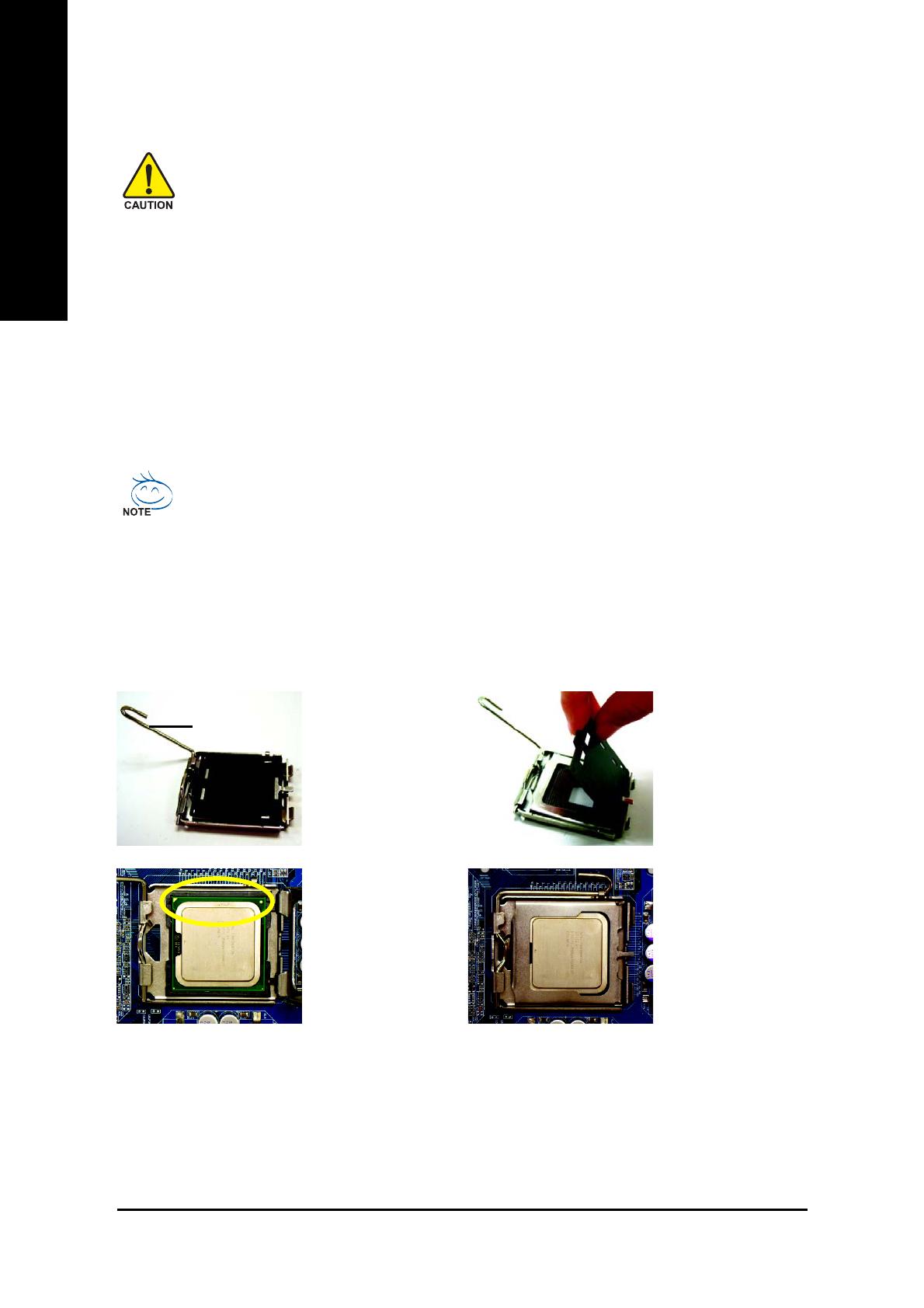
1-3-1 Installation of the CPU
Fig. 1
Gently lift the metal
lever located on the
CPU socket to the
upright position.
Metal Lever
Fig. 2
Remove the plastic
covering on the CPU
socket.
Fig. 3
Notice the small gold
colored triangle lo-
cated on the edge of
the CPU socket.
Align the
Fig. 4
Once the CPU is
properly inserted,
please replace the
plastic covering and
push the metal lever
back into its original
position.
indented corner of the CPU with the triangle and
gently insert the CPU into position. (Grasping the
CPU firmly between your thumb and forefinger,
carefully place it into the socket in a straight and
downwards motion. Avoid twisting or bending
motions that might cause damage to the CPU dur-
ing installation.)
Hardware Installation- 8 -
English
1-3-2 Installation of the Heatsink
The heatsink may adhere to the CPU as a result of hardening of the heatsink paste.To prevent
such an occurrence, it is suggested that either thermal tape rather than heat sink paste be used
for heat dissipation or using extreme care when removing the heatsink.
Fig. 6
Finally, please attach the power connector of the
heatsink to the CPU fan header located on the
motherboard.
Fig. 3
Place the heatsink atop the CPU and make sure
the push pins aim to the pin hole on the
motherboard.Pressing down the push pins di-
agonally.
Fig. 4
Please make sure the Male and Female push pin
are joined closely. (for detailed installation instruc-
tions, please refer to the heatsink installation sec-
tion of the user manual)
Fig. 5
Please check the back of motherboard after in-
stalling. If the push pin is inserted as the picture,
the installation is complete.
Fig.1
Please apply an even layer of heatsink paste on
the surface of the installed CPU.
Fig. 2
(Turning the push pin along the direction of arrow
is to remove the heatsink, on the contrary, is to
install.)
Please note the direction of arrow sign on the male
push pin doesn't face inwards before installation.
(This instruction is only for Intel boxed fan)
Male Push Pin
Female Push Pin
The top of Female Push Pin
GA-8S649MF-FS Motherboard - 9 -
English
1. The DIMM slot has a notch, so the DIMM
memory module can only fit in one direction.
2. Insert the DIMM memory module vertically
into the DIMM slot. Then push it down.
3. Close the plastic clip at both edges of the DIMM
slots to lock the DIMM module.
Reverse the installation steps when you wish
to remove the DIMM module.
The motherboard supports DDR memory modules, whereby BIOS will automatically detect memory
capacity and specifications. Memory modules are designed so that they can be inserted only in one
direction. The memory capacity used can differ with each slot.
Before installing the memory modules, please comply with the following conditions:
1. Please make sure that the memory used is supported by the motherboard. It is
recommended that memory of similar capacity, specifications and brand be used.
2. Before installing or removing memory modules, please make sure that the computer
power is switched off to prevent hardware damage.
3. Memory modules have a foolproof insertion design. A memory module can be installed
in only one direction. If you are unable to insert the module, please switch the direction.
1-4 Installation of Memory
Notch
DDR
Hardware Installation- 10 -
English
1-5 Connectors Introduction
1) ATX_12V
2) ATX (Power Connector)
3) CPU_FAN
4) SYS_FAN
5) FDD
6) IDE1 / IDE2
7) S_ATA0 / S_ATA1 / S_ATA2 / S_ATA3
8) F_PANEL
9) F_AUDIO
10) AUX_IN
11) F_USB1 / F_USB2
12) F_1394
13) CLR_CMOS
14) SAFE MODE
15) Battery
13
5
2
1112
13
10
4
6
7
9
8
14
15
GA-8S649MF-FS Motherboard - 11 -
English
1/2) ATX_12V/ATX (Power Connector)
With the use of the power connector, the power supply can supply enough stable power to all the
components on the motherboard. Before connecting the power connector, please make sure that
all components and devices are properly installed. Align the power connector with its proper
location on the motherboard and connect tightly.
The ATX_12V power connector mainly supplies power to the CPU. If the ATX_12V power
connector is not connected, the system will not start.
Caution!
Please use a power supply that is able to handle the system voltage requirements. It is
recommended that a power supply that can withstand high power consumption be used (300W or
greater). If a power supply is used that does not provide the required power, the result can lead to
an unstable system or a system that is unable to start.
If you use a 24-pin ATX power supply, please remove the small cover on the power connector on
the motherboard before plugging in the power cord ; Otherwise, please do not remove it.
1
3
2
4
Pin No. Definition
1 GND
2 GND
3 +12V
4 +12V
Pin No. Definition
1 3.3V
2 3.3V
3 GND
4 VCC
5 GND
6 VCC
7 GND
8 Power Good
9 5V SB(stand by +5V)
10 +12V
11 +12V
12 3.3V(Only for 24pins ATX)
13 3.3V
14 -12V
15 GND
16 PS_ON(soft On/Off)
17 GND
18 GND
19 GND
20 -5V
21 VCC
22 VCC
23 VCC
24 GND
1
12
13
24
Hardware Installation- 12 -
English
5) FDD (Floppy Connector)
The FDD connector is used to connect the FDD cable while the other end of the cable connects to
the FDD drive. The types of FDD drives supported are: 360KB, 720KB, 1.2MB, 1.44MB and
2.88MB.
Please connect the red power connector wire to the pin1 position.
CPU_FAN
SYS_FAN
1
2
33
34
3/4) CPU_FAN / SYS_FAN (Cooler Fan Power Connector)
The cooler fan power connector supplies a +12V power voltage via a 3-pin/4-pin (only for
CPU_FAN) power connector and possesses a foolproof connection design.
Most coolers are designed with color-coded power connector wires. A red power connector wire
indicates a positive connection and requires a +12V power voltage. The black connector wire is
the ground wire (GND).
Please remember to connect the power to the cooler to prevent system overheating and failure.
Caution!
Please remember to connect the power to the CPU fan to prevent CPU overheating and failure.
Pin No. Definition
1 GND
2 +12V
3 Sense
4 Speed Control
(Only for CPU_FAN)
1
1
GA-8S649MF-FS Motherboard - 13 -
English
Pin No. Definition
1 GND
2 TXP
3 TXN
4 GND
5 RXN
6 RXP
7 GND
7) S_ATA0 / S_ATA1 / S_ATA2 / S_ATA3
Serial ATA can provide 150MB/s transfer rate. Please refer to the BIOS setting for the Serial ATA
and install the proper driver in order to work properly.
6) IDE1/IDE2 (IDE1 / IDE2 Connectors)
Each IDE connector can connect with one IDE cable to connect the IDE hard drive to the computer.
It is recommended that the first hard drive be connected to the IDE1 connector while the disk drive
be connected to the IDE2 connector.
IDE1
IDE2
1
39
2
40
1
7
Hardware Installation- 14 -
English
8) F_PANEL (Front Panel Jumper)
Please connect the LED, reset switch and power switch etc. of your chassis front panel to
the F_PANEL connector according to the pin assignment below.
HD (IDE Hard Disk Active LED) Pin 1: LED anode(+)
Pin 2: LED cathode(-)
RES (Reset Switch) Open: Normal Operation
Close: Reset Hardware System
PW (Power Switch) Open: Normal Operation
Close: Power On/Off
MSG (Message LED/Power/Sleep LED) Pin 1: LED anode(+)
Pin 2: LED cathode(-)
NC NC
1
2
5
10
HD-
HD+
RES+
RES-
NC
MSG-
MSG+
PW-
PW+
IDE Hard Disk
Active LED
Message LED/
Sleep LED
Power
Switch
Reset Switch
GA-8S649MF-FS Motherboard - 15 -
English
10) AUX_IN
Connect other device (such as PCI TV Tuner audio out) to the connector.
1
9) F_AUDIO (Front Audio Panel Connector)
Please make sure the pin assignments on the cable are the same as the pin assignments of the
F_AUDIO connector on the motherboard. To find out if the chassis you are buying support front
audio panel connector, please contact your dealer. If you want to use "Front Audio" connector, you
must remove the jumpers on pin 5-6, 9-10.
Pin No. Definition
1 MIC
2 GND
3 REF
4 POWER
5 FrontAudio(R)
6 Rear Audio (R)/ Return R
7NC
8 No Pin
9 FrontAudio (L)
10 Rear Audio (L)/ Return L
1
10 9
2
Pin No. Definition
1 AUX-L
2 GND
3 GND
4 AUX-R
Hardware Installation- 16 -
English
11) F_ USB1 / F_USB2 (Front USB Connector)
Be careful with the polarity of the front USB connector. Check the pin assignment carefully while
you connect the front USB cable, incorrect connection between the cable and connector will make
the device unable to work or even damage it. For optional front USB cable, please contact your
local dealer.
Pin No. Definition
1 Power
2 Power
3 USB DX-
4 USB Dy-
5 USB DX+
6 USB Dy+
7 GND
8 GND
9 No Pin
10 NC
1
2
9
10
16) F1_1394 (IEEE 1394 Connector)
Serial interface standard set by Institute of Electrical and Electronics Engineers, which has features
like high speed, high bandwidth and hot plug. Be careful with the polarity of the IEEE1394 connec
tor.
Check the pin assignment carefully while you connect the IEEE1394 cable, incorrect connec
tion between the cable and connector will make the device unable to work or even damage it. For
optional IEEE1394 cable, please contact your local dealer.
Pin No. Definition
1 TPA2+
2 TPA2-
3 GND
4 GND
5 TPB2+
6 TPB2-
7 Power
8 Power
9 No Pin
10 GND
1
2
9
10
GA-8S649MF-FS Motherboard - 17 -
English
14) SAFE MODE
13) CLR_CMOS (Clear CMOS)
You may clear the CMOS data to its default values by this jumper. To clear CMOS, temporarily
short 1-2 pin. Default doesn't include the "Shunter" to prevent from improper use this jumper.
1
1
Open: Normal
Short :Clear CMOS
1
2-3 Short :SAFE MODE
System runs into BIOS setup
screen directly without POST
1
1-2 Short : Normal (Default)
1
Open :Recovery
System runs into floppy and
proceed the recovery routine
Hardware Installation- 18 -
English
15) Battery
Danger of explosion if battery is incorrectly replaced.
Replace only with the same or equivalent type
recommended by the manufacturer.
Dispose of used batteries according to the manufacturer's
instructions.
If you want to erase CMOS...
1.Turn OFF the computer and unplug the power cord.
2.Remove the battery, wait for 30 seconds.
3.Re-install the battery.
4.Plug the power cord and turn ON the computer.
BIOS Setup- 27 -
English
BIOS (Basic Input and Output System) includes a CMOS SETUP utility which allows user to configure
required settings or to activate certain system features.
The CMOS SETUP saves the configuration in the CMOS SRAM of the motherboard.
When the power is turned off, the battery on the motherboard supplies the necessary power to the
CMOS SRAM.
When the power is turned on, pushing the <Del> button during the BIOS POST (Power-On Self Test) will
take you to the CMOS SETUP screen. You can enter the BIOS setup screen by pressing "Ctrl + F1".
When setting up BIOS for the first time, it is recommended that you save the current BIOS to a disk in
the event that BIOS needs to be reset to its original settings. If you wish to upgrade to a new BIOS, either
Gigabyte's Q-Flash or @BIOS utility can be used.
Q-Flash allows the user to quickly and easily update or backup BIOS without entering the operating
system.
@BIOS is a Windows-based utility that does not require users to boot to DOS before upgrading BIOS but
directly download and update BIOS from the Internet.
CONTROL KEYS
< >< >< >< > Move to select item
<Enter> Select Item
<Esc> Main Menu - Quit and not save changes into CMOS Status Page Setup Menu
and Option Page Setup Menu - Exit current page and return to Main Menu
<Page Up> Increase the numeric value or make changes
<Page Down> Decrease the numeric value or make changes
<F1> General help, only for Status Page Setup Menu and Option Page Setup Menu
<F2> Item Help
<F5> Restore the previous CMOS value from CMOS, only for Option Page Setup
Menu
<F6> Load the file-safe default CMOS value from BIOS default table
<F7> Load the Optimized Defaults
<F8> Q-Flash utility
<F9> System Information
<F10> Save all the CMOS changes, only for Main Menu
Main Menu
The on-line description of the highlighted setup function is displayed at the bottom of the screen.
Status Page Setup Menu / Option Page Setup Menu
Press F1 to pop up a small help window that describes the appropriate keys to use and the possible
selections for the highlighted item. To exit the Help Window press <Esc>.
Chapter 2 BIOS Setup
GA-8S649MF-FS Motherboard - 28 -
English
The Main Menu (For example: BIOS Ver. : E17)
Once you enter Award BIOS CMOS Setup Utility, the Main Menu (as figure below) will appear on the
screen. Use arrow keys to select among the items and press <Enter> to accept or enter the sub-menu.
If you can't find the setting you want, please press "Ctrl+F1" to access hidden advanced
options.
Standard CMOS Features
This setup page includes all the items in standard compatible BIOS.
Advanced BIOS Features
This setup page includes all the items of Award special enhanced features.
Integrated Peripherals
This setup page includes all onboard peripherals.
Power Management Setup
This setup page includes all the items of Green function features.
PnP/PCI Configuration
This setup page includes all the configurations of PCI & PnP ISA resources.
PC Health Status
This setup page includes information about the CPU autodetected temperature, voltage, and fan,
speed.
MB Intelligent Tweaker (M.I.T.)
This setup page is to control CPU clock and frequency.
Load Fail-Safe Defaults
Fail-Safe Defaults refers to the value of the system parameters with which the system would be
in safe configuration.
Load Optimized Defaults
Optimized Defaults refers to the value of the system parameters with which the system would be
in best performance configuration.
CMOS Setup Utility-Copyright (C) 1984-2005 Award Software
` Standard CMOS Features
` Advanced BIOS Features
` Integrated Peripherals
` Power Management Setup
` PnP/PCI Configurations
` PC Health Status
` MB Intelligent Tweaker (M.I.T.)
Load Fail-Safe Defaults
Load Optimized Defaults
Set Supervisor Password
Set User Password
Save & Exit Setup
Exit Without Saving
Esc: Quit KLJI: Select Item
F10: Save & Exit Setup
Time, Date, Hard Disk Type...
  • Page 1 1
  • Page 2 2
  • Page 3 3
  • Page 4 4
  • Page 5 5
  • Page 6 6
  • Page 7 7
  • Page 8 8
  • Page 9 9
  • Page 10 10
  • Page 11 11
  • Page 12 12
  • Page 13 13
  • Page 14 14
  • Page 15 15
  • Page 16 16
  • Page 17 17
  • Page 18 18
  • Page 19 19
  • Page 20 20
  • Page 21 21
  • Page 22 22
  • Page 23 23
  • Page 24 24
  • Page 25 25
  • Page 26 26
  • Page 27 27
  • Page 28 28
  • Page 29 29
  • Page 30 30
  • Page 31 31
  • Page 32 32
  • Page 33 33
  • Page 34 34
  • Page 35 35

Gigabyte GA-8S649MF-FS User manual

Category
Motherboards
Type
User manual

Gigabyte GA-8S649MF-FS motherboard supports the latest Intel Pentium 4 LGA775 CPU with Hyper-Threading Technology and FSB up to 800MHz. It has 2 DDR DIMM memory slots that support DDR400/333/266 and up to 2GB of memory. For storage, it features 2 IDE connections (UDMA 33/ATA 66/ATA 100) and 4 Serial ATA connections. It also includes a PCI Express x16 slot, 3 PCI slots, and 8 USB 2.0/1.1 ports. Onboard, it has Realtek 8201CL chip for 10/100 Mbit Ethernet and ALC655 CODEC for audio. The motherboard also supports IEEE1394 ports and PS/2 keyboard and mouse.

Ask a question and I''ll find the answer in the document

Finding information in a document is now easier with AI