Page is loading ...

USER’S MANUAL
GA-8IAX
Pentium Prescott 800 Motherboard
Pentium
®
Prescott Processor Motherboard
Rev. 1001
12ME-8IAX-1001

2
English
GA-8IAX Motherboard
Table of Content
Item Checklist .........................................................................................4
WARNING!...............................................................................................4
Chapter 1 Introduction............................................................................5
Features Summary...................................................................................... 5
GA-8IAX Motherboard Layout...................................................................... 7
Chapter 2 Hardware Installation Process...............................................9
Step 1: Installing Processor and CPU Haet Sink ......................................10
Step1-1: Installing CPU................................................................................................... 10
Step1-2: Installing Heat Sink ............................................................................................11
Step 2: Install memory modules................................................................12
Step 3: Install expansion cards .................................................................14
Step 4: Connect ribbon cables, cabinet wires, and power supply ..........15
Step 4-1 : I/O Back Panel Introduction .......................................................................... 15
Step 4-2 :Connectors & Jumper Setting Introduction ................................................... 18
Chapter 3 BIOS Setup ..........................................................................32
The Main Menu (For example: BIOS Ver. : D4)........................................33
Standard CMOS Features.........................................................................35
Advanced BIOS Features ..........................................................................38
Integrated Peripherals ..............................................................................41
Power Management Setup .......................................................................46
PC Health Status........................................................................................48
Load Fail-Safe Defaults.............................................................................50
Load Optimized Defaults...........................................................................50
Set Supervisor/User Password..................................................................51
Save & Exit Setup.......................................................................................52
Exit Without Saving ...................................................................................52

English
3
Table of Content
Chapter 4 Technical Reference ............................................................53
Block Diagram...........................................................................................53
Chapter 5 Driver Installation ..................................................................54
A.Intel Chipset Software Installation Utility .................................................................... 54
B.Broadcom Network Driver Installation ....................................................................... 56
C.Realtek Audio Driver................................................................................................... 57
D.DirectX 9.0 Driver Installation...................................................................................... 58
E.Intel SATA Driver Installation ....................................................................................... 59
Chapter 6 Appendix..............................................................................61
Acronyms ....................................................................................................................... 61

4
English
GA-8IAX Motherboard
Computer motherboards and expansion cards contain very delicate Integrated Circuit (IC) chips. To
protect them against damage from static electricity, you should follow some precautions whenever you
work on your computer.
1. Unplug your computer when working on the inside.
2. Use a grounded wrist strap before handling computer components. If you do not have
one, touch both of your hands to a safely grounded object or to a metal object, such as
the power supply case.
3. Hold components by the edges and try not touch the IC chips, leads or connectors, or
other components.
4. Place components on a grounded antistatic pad or on the bag that came with the
components whenever the components are separated from the system.
5. Ensure that the ATX power supply is switched off before you plug in or remove the ATX
power connector on the motherboard.
If the motherboard has mounting holes, but they don’t line up with the holes on the base and
there are no slots to attach the spacers, do not become alarmed you can still attach the spacers to
the mounting holes. Just cut the bottom portion of the spacers (the spacer may be a little hard to
cut off, so be careful of your hands). In this way you can still attach the motherboard to the base
without worrying about short circuits. Sometimes you may need to use the plastic springs to isolate
the screw from the motherboard PCB surface, because the circuit wire may be near by the hole. Be
careful, don’t let the screw contact any printed circuit write or parts on the PCB that are near the
fixing hole, otherwise it may damage the board or cause board malfunctioning.
Installing the motherboard to the chassis…
WARNING!
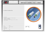
The GA-8IAX motherboard Serial ATA cable x 4
IDE (ATA133 ) cable x 1 / Floppy cable x 1 I/O Shield
CD for motherboard driver & utility GA-8IAX user’s manual
Item Checklist

5
Introduction
Chapter 1 Introduction
Features Summary
Form Factor y 30.6cm x 24.4cm ATX size form factor, 6 layers PCB.
CPU y Supports Intel
®
Pentium Prescot LGA 775 processor
y Intel
®
Prescot LGA 775 supports 800MHz FSB
y L2 cache on-die per processor from 1M
Chipset y Intel
®
Alderwood 925X Chipset
y Intel
®
ICH6R
Memory y 4 x 240-pin DDRII DIMM sockets
y Supports 4 ECC Un-buffered DIMM DDRII 400
y Support 128MB, 256MB, 512MB, and 1GB memory
y Single-bit Errors Correction, Multiple-bit Errors Detection
I/O Control y ITE IT8712F Super I/O
Expansion Slots y Supports 4 PCI slots 32-Bit/33MHz (5V)
y Supports 1 PCI-E x16 slot
y Supports 1 PCI-E x 1 slot
On-Board RAID y ICH6R
y Supports SATA RAID 0,1
On-Board Peripherals y 1 Floppy port supports 2 FDD with 360K, 720K,1.2M, 1.44M
and 2.88M bytes.
y 1 Parallel port supports Normal/EPP/ECP mode
y 1 Serial port (COM)
y 4 x USB 2.0 (2 by cable)
y 2 x IEEE 1394 ( 1 by cable)
y 1 x LAN RJ45
y 4 x SATA Connectors
Hardware Monitor y CPU/Power/System Fan Revolution Detect
y CPU shutdown when overheat
y System Voltage Detect
On-Board LAN y Broadcom 5751 Gigabit Ethernet (PCI-E)
On-Board USB 2.0 y Built in ICH6R Chipset
PS/2 Connector y PS/2 Keyboard interface and PS/2 Mouse interace
BIOS y Award BIOS on 4Mb flash RAM

6
English
GA-8IAX Motherboard
Additional Features y PS/2 Mouse power on under Windows Operating System
y External Modem wake up
y Supports S1, S3, S4, S5 under Windows Operating System
y Wake on LAN (WOL)
y AC Recovery
y Supports Console Redirection

7
Introduction
GA-8IAX Motherboard Layout
A
E
B
C
D
F
N
O
P
Q
R
G
H
I
J
K
L
M
T
U
S
V
X
Y
W
2
1
5
346
8
7
9
10
11
12
13
14
15
16
17
18

8
English
GA-8IAX Motherboard
A. CPU 1. PCIE_16 (x16)
B. Intel Alderwood 925X 2. PCIE_1 (x 4)
C. Intel ICH6R 3. PCI_1
D. BIOS 4. PCI_2
E. BAT (Li-Battery) 5. PCI_3
F. Broadcom 5751 6 PCI_4
G. IDE 7. DDRII1
H. FDD 8. DDRII2
I. F_Panel (Front Panel) 9. DDRII3
J. F_USB2 (Front USB) 10. DDRII4
K. F_USB1 (Front USB) 11. ATX
L. F_1394 (IEEE 1394) 12. ATX_12V
M. F_Audio_ACZ 13. Audio
N. CI 14. USB_LAN2
O. SCSI LED 15. USB_1394
P. CD_IN 16. LPT
Q. ITE IT8712F 17. COMA
R. SATA_0 18. KB_MS (Keyboard and Mouse)
S. SATA_1
T. SATA_2
U. SATA_3
V. CPU_FAN (CPU Fan Connector)
W. SYS_FAN (System Fan Connector)
X Front_FAN
Y. PSU_FAN (Power Supply Fan)

9
Hardware Installation Process
To set up your computer, you must complete the following steps:
Step 1- Install the Central Processing Unit (CPU)
Step 2- Install memory modules
Step 3- Install expansion cards
Step 4- Connect ribbon cables, cabinet wires, and power supply
Step 5- Setup BIOS software
Chapter 2 Hardware Installation Process
Step 2
Step1
Step3
Step 4
Step4
Step 4
Step 4
Step4

10
English
GA-8IAX Motherboard
Step 1: Installing Processor and CPU Haet Sink
Before installing the processor and cooling fan, adhere to the following cautions:
Step1-1: Installing CPU
Step 1 Gently lift the metal lever located on the CPU socket to the upper-right position.
Step 2 Remove the plastic covering on the CPU socket.
Step 3 Align the indented corner of the CPU with the triangle and gently insert the CPU into position.
(Grasping the CPU firmly between your thumb and forefinger, carefully place it into the socket
in a straight and downwards motion. Avoid twisting or bending motions that might cause
damage to the CPU during installation.)
Step 4 Once the CPU is properly inserted, please replace the plastic covering and push the metal
lever back into its original position.
Step 5 Close the lever, reverse step 1 & 2.
1.The processor will overheat without the heatsink and/or fan, resulting in permanent
irreparable damage.
2. Never force the processor into the socket.
3.Apply thermal grease on the processor before placing cooling fan.
4. Please make sure the CPU type is supported by the motherboard.
5. If you do not match the CPU socket Pin 1 and CPU cut edge well, it will cause improper
installation. Please change the insert orientation.

11
Hardware Installation Process
Step1-2: Installing Heat Sink
Fig.1
Please apply heatsink paste on the surface of
the installed CPU.
Fig. 2
( to remove the heatsink, turning the push pin along
the direction of arrow; and reverse the previous
step to install the heat sink.)
Please note the direction of arrow sign on the male
push pin doesn't face inwards before installation.
(This instruction is only for Intel boxed fan)
Fig. 3
Place the heatsink on top the CPU and make
sure the push pins align to the pin hole on the
motherboard.Push down the push pins
diagonally.
Fig. 4
Please make sure the Male and Female push pin
are brought together. (for detailed installation
instructions, please refer to the heatsink installation
section of the user manual)
Male Push Pin
Female Push Pin
The top of Female Push Pin
Fig. 6
Attach the power connector of the heatsink to the
CPU fan header located on the motherboard.
Fig. 5
Please check the back side of teh motherboard.
Make sure the push pin is seated firmly as the
picture shown. Installation completed.

12
English
GA-8IAX Motherboard
Step 2: Install memory modules
Before installing the processor and heatsink, adhere to the following warning:
When DIMM LED is ON, do not install/remove DIMM from socket.
Please note that the DIMM module can only fit in one direction due to the one notches. Wrong
orientation will cause improper installation. Please change the insert orientation.
GA-8IAX has 4 dual inline memory module (DIMM) socets. It supports the Dual Channel Technology.
The BIOS will automatically detects memory type and size. To install the memory module, just push it
vertically into the DIMM socket .The DIMM module can only fit in one direction due to the notch. Memory
size can vary between sockets.
Channel B
Channel A
DDRII
Notch

13
Hardware Installation Process
Installation Step:
1. The DIMM slot has a notch, so the DIMM memory module can only fit in one direction.
2. Insert the DIMM memory module vertically into the DIMM slot. Then push it down.
3. Close the plastic clip at both edges of theDIMM slots to lock the DIMM module.
4. When installing the DIMM into the DIMM module, we recommend to populate one DIMM in
Channel A module and one in Channel B module for best performance.
Please note that each logical DIMM must be madeof two identical DIMMs having the same
device size on each and the same DIMM size.
5. Reverse the installation steps when you wish to remove the DIMM module.
DDR DIMM Supported Configuration
ygolonhceTnoitarugifnoC
woRfo#
stiBsserdA
nmuloCfo#
stiBsserdA
knaBfo#
stiBsserdA
egaP
eziS
knaR
eziS
tibM65261xM6
13192K4BM821
tibM6528xM2331012K8BM652
tibM2158xM2331012K8BM652
tibM2158xM4631112K61BM215
tibM2158xM4641012K8BM215
tibG161xM4641012K8BM215
tibG
18xM82141112K61BG1
tibG161xM4631013K8BM215
tibG18xM82141013K8BG1
Notch

14
English
GA-8IAX Motherboard
Step 3: Install expansion cards
1. Read the related expansion card’s instruction document before install the expansion card into
the computer.
2. Remove your server’s chassis cover, necessary screws and slot bracket from the computer.
3. Press the expansion card firmly into expansion slot in motherboard.
4. Be sure the metal contacts on the card are indeed seated in the slot.
5. Replace the screw to secure the slot bracket of the expansion card.
6. Replace your computer’s chassis cover.
7. Power on the computer, if necessary, setup BIOS utility of expansion card from BIOS.
8. Install related driver from the operating system.
Please carefully pull out the small white-
drawable bar at the end of the
PCI Express x 4 slot when you try to
install/Uninstall the VGA card. Please align
the VGA card to the onboard
PCI Express x 4 slot and fully seated.
Make sure your VGA card is locked by
the small white-drawable bar.

15
Hardware Installation Process
Step 4: Connect ribbon cables, cabinet wires, and power
supply
Step 4-1 : I/O Back Panel Introduction
X
Y
Z
[
\
]
^
_

16
English
GA-8IAX Motherboard
LAN LED Description
Color Condition Description
Green ON LAN Link / no Access
Green BLINK LAN Access
- OFF Idle
Green ON 100Mbps connection
- OFF 10Mbps connection
Yellow ON 1Gbps connection
Yellow BLINK Port identification with 1Gbps connection
Green ON 100Mbps connection
Green BLINK Port identification with 10 or 100Mbps connection
- OFF 10Mbps connection
Name
LAN
Link/Activity
10/100 LAN
Speed
GbE LAN
Speed
X PS/2 Keyboard and PS/2 Mouse Connector
To install a PS/2 port keyboard and mouse, plug the mouse to the upper port (green) and the keyboard
to the lower port (purple).
Y/Z Parallel Port / Serial Port
This connector supports 1 standard COM port and 1 Parallel port. Device like printer can be
connected to Parallel port ; mouse and modem etc can be connected to Serial port.
[ IEEE 1394 Port
Connects the IEEE1394 devices to this connector.
\/] USB port
Before you connect your device(s) into USB connector(s), please make sure your device(s) such
as USB keyboard, mouse, scanner, zip, speaker...etc. have a standard USB interface.
Also make sure your OS supports USB controller. If your OS does not support USB controller,
please contact OS vendor for possible patch or driver upgrade. For more information please
contact your OS or device(s) vendors.
^^
^^
^ LAN Port
The provided Internet connection is Gigabit Ethernet, providing data transfer speeds of 10/100/
1000Mbps.

17
Hardware Installation Process
_ Audio Connector
After install onboard audio driver, you may connect
speaker to Line Out jack, micro phone to MIC In jack.
Device like CD-ROM , walkman etc can be connected
to Line-In jack.
Please note:
You are able to use 2-/4-/6- channel audio feature by
S/W selection.
If you want to enable 6-channel function, you have 2
choose for hardware connection.
Method1:
Connect “Front Speaker” to “Line Out”
Connect “Rear Speaker” to “Line In”
Connect “Center and Subwooferr” to “MIC In “.
Line Out
(Front Speaker)
Line In
(Rear Speaker)
MIC In
(Center and Subwoofer)

18
English
GA-8IAX Motherboard
Step 4-2 :Connectors & Jumper Setting Introduction
A) ATX1 O) F_AUDIO_ACZ
B) ATX 12V P) CD_IN
C) IDE Q) SCSI_LED
D) FDD R) CPU_FAN
E) SATA_0 S) SYS_FAN
F) SATA_1 T) FRONT_FAN
G) SATA_2 U) PSU_FAN
H) SATA_3
I) F_1394 1) JP1
J) F_USB2 2) JP3
K) F_USB1 3) PWR_JP1
L) F_Panel 4) PWR_JP2
M) BAT 5) PWR_JP3
N) CI 6) PWR_JP4
A
B
C
D
E
G
F
H
I
J
K
L
O
P
M
N
R
T
S
U
1
5
3
4
Q
2
6

19
Connector Introduction
A) ATX (ATX Power Connector)
24
13
B ) ATX_12V( +12V Power Connector)
This connector (ATX +12V) is used only for
CPU1 Core Voltage.
12
1
PIN No. Definition
1 +3.3V
2 +3.3V
3 GND
4 +5V
5 GND
6 +5V
7 GND
8 POK
9 5VSB
10 +12V
11 +12V
12 +3.3V
13 +3.3V
14 -12V
15 GND
16 PSON
17 GND
18 GND
19 GND
20 -5V
21 +5V
22 +5V
23 +5V
24 GND
AC power cord should only be connected to
your power supply unit after ATX power cable
and other related devices are firmly connected
to the mainboard.
1
Pin No. Definition
1 GND
2 GND
3 P12V-CPU0
4 P12V-CPU0

20
English
GA-8IAX Motherboard
C ) IDE Connector
Please connect first harddisk to IDE1. The red stripe of the ribbon cable must be the same side with
the Pin1.
D) FDD (Floppy Connector)
Please connect the floppy drive ribbon cables to FDD. It supports 360K,720K,1.2M,1.44M and
2.88Mbytes floppy disk types. The red stripe of the ribbon cable must be the same side with the
Pin1.
33
34
1
2
2
1
39
40
IDE
/