
SPT0001 / SPT0002 / SPT0012
ALWAYS CONSULT A DOCTOR BEFORE STARTING AN EXERCISE
PROGRAM
PLEASE CAREFULLY READ THIS ENTIRE MANUAL BEFORE
OPERATING YOUR NEW ELLIPTICAL!
Z100 / Z300
Z500
Z700
OWNER’S MANUAL
XE 100
Elliptical
XE 200
Elliptical
XE 300
Elliptical

XE100 / XE200 / XE300 Elliptical
1
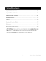
Important Safety Instructions…………………………………………………………………3
Important Electrical Information………………………………………………………………4
Important Operation Instructions……………………………………………………………..4
Assembly Instructions………………………………………………………………………….5
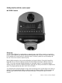
Features……………………………………………………………………………………….. 21
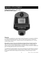
Operation of Your New Elliptical……………………………………………………………..22
Maintenance……………………………………………………………………………………43
Manufacturer’s Limited Warranty…………………………………………………………….44
ATTENTION-THIS ELLIPTICAL IS INTENDED FOR RESIDENTIAL USE
ONLY AND IS WARRANTED FOR THAT APPLICATION. ANY OTHER
APPLICATION VOIDS THIS WARRANTY IN ITS ENTIRETY.
Table of Contents

XE100 / XE200 / XE300 Elliptical
2
Thank you for your purchase of this quality elliptical trainer. Your new elliptical was
manufactured by one of the leading fitness manufacturers in the world and is backed by
one of the most comprehensive warranties available.
Please take a moment at this time to record the name of the dealer and the date of
purchase below to make any future, needed contact easy. We appreciate your support
and we will always remember that you are the reason that we are in business.
Yours in Health,
Action Fitness Equipment Pty Ltd.
Name of Dealer______________________________________
Purchase Date_______________________________________
CONGRATULATIONS ON YOUR
NEW ELLIPTICAL AND WELCOME
TO THE SPIRIT FAMILY!

XE100 / XE200 / XE300 Elliptical
3
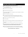
WARNING - Read all instructions before using this appliance.
■ Do not operate elliptical on deeply padded, plush or shag carpet. Damage to both
carpet and elliptical may result.
■ Keep children away from the elliptical.
■ Keep hands away from all moving parts.
■ Never operate the elliptical if it has a damaged cord or plug. If the elliptical is not working
properly, call your dealer.
■ Keep the cord away from heated surfaces.
■ Do not operate where aerosol spray products are being used or where oxygen is
being administered. Sparks from the motor may ignite a highly gaseous environment.
■ Never drop or insert any object into any openings.
■ Do not use outdoors.
■ To disconnect, turn all controls to the off position, then remove the plug from the outlet.
■ Do not attempt to use your elliptical for any purpose other than for the purpose it is
intended.
■ The hand pulse sensors are not medical devices. Various factors, including the user’s
movement, may affect the accuracy of heart rate readings. The pulse sensors are
intended only as exercise aids in determining heart rate trends in general.
■ Wear proper shoes. High heels, dress shoes, sandals or bare feet are not suitable
for use on your elliptical. Quality athletic shoes are recommended to avoid leg fatigue.
SAVE THESE INSTRUCTIONS - THINK SAFETY!
Important Safety Instructions

XE100 / XE200 / XE300 Elliptical
4
WARNING!
● NEVER remove any cover without first disconnecting AC power supply.
● If A.C. voltage varies by ten percent (10%) or more, the performance of your elliptical may
be affected. Such conditions are not covered under your warranty. If you suspect the
voltage is low, contact your local power company or a licensed electrician for proper testing.
● NEVER expose this elliptical to rain or moisture. This product is NOT designed for
Use outdoors, near a pool or spa, or in any other high humidity environment. Maximum
environmental ratings are 4-48 degrees Celsius, 95% humidity non-condensing (no water
droplets forming on surfaces).
● NEVER operate this elliptical without reading and completely understanding the results of
any operational change you request from the computer.
● Understand that changes in resistance do not occur immediately. Set your desired level on
the computer console and release the adjustment key. The computer will obey the
command gradually.
● NEVER use your elliptical during an electrical storm. Surges may occur in your household
power supply that could damage elliptical components.
● Use caution while participating in other activities while using your elliptical such as watching
television, reading, etc. These distractions may cause you to lose balance and may result in
serious injury.
● Always hold on to a handrail or hand bar while making control changes.
Do not use excessive pressure on console control keys. They are precision set to properly
function with little finger pressure. Pushing harder is not going to make the unit go faster or
slower. If you feel the buttons are not functioning properly with normal pressure, contact your
Spirit dealer.
Important Electrical Information
Important Operation Instructions

XE100 / XE200 / XE300 Elliptical
5
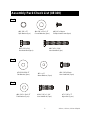
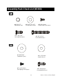
Assembly Pack Check List (XE100)
#66. M5 x 10m/m
Phillips Head Screw (4pcs)
#103. 3/8" x 3/4"
Hex Head Bolt (2pcs)
#60. 3/8" x 2-1/4"
Hex Head Bolt (1pc)
#96. 3/8" x 2T
Split Washer (1pc)
#84. 3/8" x 23 x 1.5T
Curved Washer (2pcs)
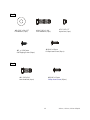
#79.5/16"x23x1.5T
Flat Washer (2pcs)
#59. 5/16"x15m/m
Hex Head Bolt (2 pcs)
#83. ψ 17
Wave Washer (2 pcs)
#104. 5/16” x 1-1/4”
Hex Head Bolt (2 pcs)
#80. 5/16" x 20x 1.5T
Flat Washer (2 pcs)
#71. 5/16" x 7T
Nylon Nut (2 pcs)
Step 3
Step 2
Step 1

XE100 / XE200 / XE300 Elliptical
6
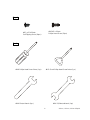
#87. ψ 3.5x12m/m
Self Tapping Screw (10pcs)
#105.M5 x 15m/m
Phillips Head Screw (17pcs)
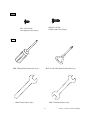
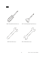
#108. Phillips Head Screw Driver (1 pc) #107. Short Phillips Head Screw Driver (1 pc)
#109. 12m/m Wrench (1pc)
#106. 13/14m/m Wrench (1pc)
Tools
Step 4

XE100 / XE200 / XE300 Elliptical
7
Assembly Pack Check List (XE200)
Step 1
Step 2
Step 3
#66. M5 x 10m/m
Phillips Head Screw (4pcs)
#103. 3/8" x 3/4"
Hex Head Bolt (2pcs)
#60. 3/8" x 2-1/4"
Hex Head Bolt (1pc)
#96. 3/8" x 2T
Split Washer (1pc)
#84. 3/8" x 23 x 1.5T
Curved Washer (2pcs)
#97.3/8"x30x2T
Flat Washer (2pcs)
#103. 3/8"x3/4"
Hex Head Bolt (2 pcs)
#81. ψ 25
Wave Washer (2 pcs)
#104. 5/16” x 1-1/4”
Hex Head Bolt (2 pcs)
#80. 5/16" x 20 x 1.5T
Flat Washer (2 pcs)
#71. 5/16" x 7T
Nylon Nut (2 pcs)

XE100 / XE200 / XE300 Elliptical
8
Tools
Step 4
#87. ψ 3.5x12m/m
Self Tapping Screw
(18pcs)
#105.M5 x 15m/m
Phillips Head Screw (21pcs)
#108. Phillips Head Screw Driver (1 pc) #107. Short Phillips Head Screw Driver (1 pc)
#109. 12m/m Wrench (1pc)
#106. 13/14m/m Wrench (1pc)

XE100 / XE200 / XE300 Elliptical
9
■ UNPACKING THE UNIT
1. Using a razor knife (Box Cutter) cut the outside, bottom, edge of box along the dotted Line. Lift
Box over the unit and unpack.
2. Carefully remove all parts from carton and inspect for any damage or missing parts. If damaged
parts are found, or parts are missing, contact your dealer immediately.
3. Locate the hardware package. The hardware is separated into steps. Remove the tools first.
Remove the hardware for each step as needed to avoid confusion.
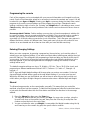
STEP 1: CONSOLE MAST ASSEMBLY
1.
Locate the Console Mast (12)
and
Console Mast Cover (41)
and
slide the Cover
onto
the
Mast as
far as
it
will
go. Make sure the Console Mast Cover is
facing the correct way.
2.
At the
top opening
of
the Main
Frame
of
the elliptical
is
a
Computer
Cable. Unravel
and
straighten out the Computer Cable (31) and feed it
into the
bottom of the console mast tube
and out of the top
opening.
3.
Install
the Console
Mast into
the receiving
bracket
in
the top
of
the Main
Frame. NOTE: there
is one bolt
already
installed in
the receiving bracket
that will
engage with the slot at the bottom
of the Console Mast. This
needs
to be
tightened at the end along with the three other
console
mast bolts.
4.
Put
one
3/8"
x
2T
Split
Washer (96)
onto the
3/8"
x
2-1/4" Long
Hex
Head Bolt (60), and the
two 3/8
"
x 23
Curved
Washers (84)
onto the
two 3/8" x 3/4" Short Hex Head Bolts (103).
Install, and
hand
tighten, the Long Hex Head
Bolt through the left side of
the receiving
bracket
into
the
Console
Mast.
NOTE:
There is an electrical wire running through the Console Mast
Tube. Be careful not
to
damage
or pinch
this
Computer Cable
during
this
procedure. Damage
to
the
Console
could
result.
Install, and hand
tighten, the two Short Hex Head bolts
through
the
front of
the
receiving bracket into the Console Mast.
5.
Using
the
13/14m/m
Wrench
tighten
the
three
bolts
and
the
fourth bolt,
which
is pre-installed,
firmly. These
bolts should be tightened as
much as
you
possibly can.
6. There will
be three electrical wire connectors at
the top opening of
the console mast, two 2
pin
connectors (hand pulse
sensors)(36) and one 10 pin connector (main wire harness)(31).
Connect these to the
mating connectors on the back of
the electronic Console (30).
The
connectors are keyed,
you cannot
plug them
in the wrong way
so do not force them.
The two,
2 pin connectors can be plugged into
either
connector on
the back
of
the console.
7.
Storing
the
excess
wire
back
into
the
Console
Mast,
carefully
install
the
Console onto the
mounting plate of Console Mast and secure
using the four M5 x 10m/m
Phillips Head Screws.
Make sure the wires do not get pinched between the console and mounting plate.
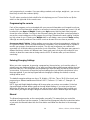
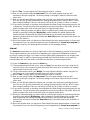
Assembly Instructions( XE100 / XE200)

XE100 / XE200 / XE300 Elliptical
10
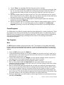
*STEP 2: XE100 ONLY: HANDLE BAR ASSEMBLY
1. Install the two 17m/m Wave Washers (83) onto the Left and Right side of the Handle Bar axle.
2. Slide the Left (10) and Right (11) Handle Bars onto the appropriate side of the axle. The
handlebars have a small sticker on them indicating L (left) and R (right).
3. Put the two 5/16" x 23mm Flat Washers onto the two 5/16" x 15m/m Hex Head Bolts and install,
and tighten, in the threaded holes in the ends of the axle.
*STEP 2: XE200 ONLY: HANDLE BAR ASSEMBLY
1. Install the two 28m/m Wave Washers (81) onto the Left and Right side of the Handle Bar axle.
2. Slide the Left (10) and Right (11) Handle Bars onto the appropriate side of the axle. The
handlebars have a small sticker on them indicating L (left) and R (right).
3. Put the two 3/8 X 30mm Flat Washers (97) onto the two 3/8” X 3/4” Hex Head Bolts (103) and
install, and tighten, in the threaded holes in the ends of the axle.
4. Connect the two wires together (124, 125) and store the excess, including plastic connectors,
back into the console mast. Place the rubber grommet (123) over the wire and snap it into the
hole in the console mast.
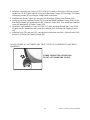
STEP 3: CONNECTING ARM ASSEMBLY
1. Align the hole in the rod end of the left Connecting arm (8) with the hole in the bracket of the
left Handle Bar (10). The rod end should be on the inner side of the Handle Bar bracket. Make
sure the ty-wrap is removed from the rod end and the sleeve spacer (22) does not fall out
during assembly. Take one 5/16" x 1-1/4" Hex Head Bolt (104) and install it through the Handle
Bar bracket and the rod end. Install one 5/16" x 20 x 1.5T Flat Washer (80) and one 5/16" x
7mm Nylon Nut (71) on the 5/16" x 1-1/4" Hex Head Bolt (104) and tighten as tight as possible
using the two12m/m Wrenches provided. Repeat the procedure for the right side Pedal
/Connecting Arm.
*STEP 4: XE100 ONLY: PLASTICS ASSEMBLY
1. Install the Connecting Arm Covers (2 each 57, 58) over the connection of the rod end and
Handle Bars with four M5 x 15m/m Screws and two 3.5x10m/m Self Tapping Screws by using
the Short Phillips Screw Driver.
2. Install the two Wheel Covers (52) using the four M5x15m/m Phillips Head Screws (105).
3. Locate the two Rear Stabilizer Covers (19,20) and two Middle Stabilizer Covers (19,20) for the
Rear Rail Assembly and install with four M5 x 15m/m Screws (105). Then install front stabilizer
cover (49) with two M5 x 15m/m Screws (105).
4. Install the Front Handle Bar Covers (54-1 left, 55-1 right) and Rear Handle Bar Cover (54 left,
55 right) over the Handle Bar axle connections with the six 3.5x10m/m Self Tapping Screws.
5. Install the front (122) and rear (121) console mast covers with three M5 x 15m/m Screws (105)
and two 3.5x12m/m Self Tapping Screws (87).
*STEP 4: XE200 ONLY: PLASTICS ASSEMBLY

XE100 / XE200 / XE300 Elliptical
1
1
2. Install the connecting arm covers (57,57-1 & 58,58-1) over the connection of the rod end and
handle bars (10 & 11) with eight M5 x 15m/m Phillips Head Screws (105) and eight 3.5x12m/m
self tapping screws (87) by using the Phillips head screw driver.
3. Install the two Wheel Covers (52) using the four M5x15m/m Phillips Head Screws (105).
4. Locate the two Rear Stabilizer Covers (19,20) and two Middle Stabilizer Covers (19,20) for the
Rear Rail Assembly and install with four M5 x 15m/m Screws (105). Then install front stabilizer
cover (49) with two M5 x 15m/m Screws (105).
5. Install the Front Handle Bar Covers (54-1 left, 55-1 right) and Rear Handle Bar Cover (54 left,
55 right) over the Handle Bar axle connections with the six 3.5x10m/m Self Tapping Screws
(87).
6. Install the front (122) and rear (121) console mast covers with three M5 x 15m/m Screws (105)
and two 3.5x12m/m Self Tapping Screws (87).
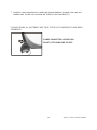
PLEASE ENSURE ALL FASTENERS ARE TIGHT AFTER THE COMPONENTS HAVE BEEN
ASSEMBLED.
POWER CONNECTOR LOCATED ON
FRONT, LEFT HAND SIDE OF UNIT.

XE100 / XE200 / XE300 Elliptical
12
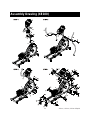
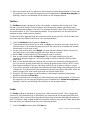
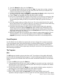
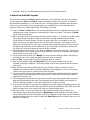
Assembly Drawing (XE100)

XE100 / XE200 / XE300 Elliptical
13
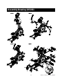
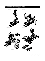
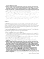
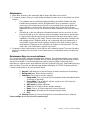
Assembly Drawing (XE200)

XE100 / XE200 / XE300 Elliptical
14
Step 1
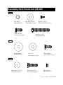
Assembly Pack Check List (XE300)
#66. M5 x 10m/m
Phillips Head Screw (4pcs)
#103. 3/8" x 3/4"
Hex Head Bolt (2pcs)
#60. 3/8" x 2-1/4"
Hex Head Bolt (1pc)
#96. 3/8" x 2T
Split Washer (1pc)
#84. 3/8" x 23 x 1.5T
Curved Washer (2pcs)
#97.3/8"x30x2T
Flat Washer (2pcs)
#103. 3/8"x3/4"mm
Hex Head Bolt (2 pcs)
#81. ψ 25 Wave
Washer (2 pcs)
#87. ψ 3.5x12m/m
Self Tapping Screw (8pcs)
Step 2

XE100 / XE200 / XE300 Elliptical
15
Step3
#87. ψ 3.5x12m/m
Self Tapping Screw (10pcs)
#105.M5 x 15m/m
Phillips Head Screw (11pcs)
#104. 5/16” x 1-1/4”
Hex Head Bolt (2 pcs)
#80. 5/16" x 20x 1.5T
Flat Washer (2 pcs)
#71. 5/16" x 7T
Nylon Nut (2 pcs)
Step 4
#105.M5 x 15m/m
Phillips Head Screw (26pcs)
#91. 5/16"x 3/4”
Hex Head Bolt (4 pcs)

XE100 / XE200 / XE300 Elliptical
16
Tools
#108. Phillips Head Screw Driver (1 pc) #107. Short Phillips Head Screw Driver (1 pc)
#109. 12m/m Wrench (1pc)
#106. 13/14m/m Wrench (1pc)

XE100 / XE200 / XE300 Elliptical
17
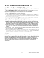
■ UNPACKING THE UNIT
1. Using a razor knife (Box Cutter) cut the outside, bottom, edge of box along the dotted Line. Lift
Box over the unit and unpack.
2. Carefully remove all parts from carton and inspect for any damage or missing parts. If damaged
parts are found, or parts are missing, contact your dealer immediately.
3. Locate the hardware package. The hardware is separated into steps. Remove the tools first.
Remove the hardware for each step as needed to avoid confusion.
STEP 1: CONSOLE MAST ASSEMBLY
1. Locate the Console Mast (12)
and
Console Mast Cover (41)
and
slide the Cover
onto
the
Mast as
far as
it
will
go. Make sure the Console Mast Cover is
facing the correct way.
2.
At the
top opening
of
the Main
Frame
of
the elliptical
is
a
Computer
Cable. Unravel
and
straighten out the Computer Cable (31) and feed it
into the
bottom of the console mast tube
and out of the top
opening.
3.
Install
the Console
Mast into
the receiving
bracket
in
the top
of
the Main
Frame. NOTE: there
is one bolt
already
installed in
the receiving bracket
that will
engage with the slot at the bottom
of the Console Mast. This
needs
to be
tightened at the end along with the three other
console
mast bolts.
4.
Put
one
3/8"
x
2T
Split
Washer (96)
onto the
3/8"
x
2-1/4" Long
Hex
Head Bolt (60), and the
two 3/8
"
x 23
Curved
Washers (84)
onto the
two 3/8" x 3/4" Short Hex Head Bolts (103).
Install, and
hand
tighten, the Long Hex Head
Bolt through the left side of
the receiving
bracket
into
the
Console
Mast.
NOTE:
There is an electrical wire running through the Console Mast
Tube. Be careful not
to
damage
or pinch
this
Computer Cable
during
this
procedure. Damage
to
the
Console
could
result.
Install, and hand
tighten, the two Short Hex Head bolts
through
the
front of
the
receiving bracket into the Console Mast.
5.
Using
the
13/14m/m
Wrench
tighten
the
three
bolts
and
the
fourth bolt,
which
is pre-installed,
firmly. These
bolts should be tightened as
much as
you
possibly can.
6. There will
be three electrical wire connectors at
the top opening of
the console mast, two 2
pin
connectors (hand pulse
sensors)(36) and one 10 pin connector (main wire harness)(31).
Connect these to the
mating connectors on the back of
the electronic Console (30).
The
connectors are keyed,
you cannot
plug them
in the wrong way
so do not force them.
The two,
2 pin connectors can be plugged into
either
connector on
the back
of
the console.
7.
Storing
the
excess
wire
back
into
the
Console
Mast,
carefully
install
the
Console onto the
mounting plate of Console Mast and secure
using the four M5 x 10m/m
Phillips Head Screws.
Make sure the wires do not get pinched between the console and mounting plate.
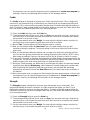
Assembly Instructions (XE300)

XE100 / XE200 / XE300 Elliptical
18
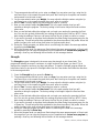
STEP 2: HANDLE BAR ASSEMBLY
1. Install the two 28m/m Wave Washers (81) onto the Left and Right side of the Handle Bar axle.
2. Slide the Left (10) and Right (11) Handle Bars onto the appropriate side of the axle. The
handlebars have a small sticker on them indicating L (left) and R (right).
3. Put the two 3/8 X 30mm Flat Washers (97) onto the two 3/8” X 3/4” Hex Head Bolts (103) and
install, and tighten, in the threaded holes in the ends of the axle.
4. Connect the two wires together (124, 125) and store the excess, including plastic connectors,
back into the console mast. Place the rubber grommet (123) over the wire and snap it into the
hole in the console mast.
5. Install the Front Handle Bar Covers (54-1 left, 55-1 right) and Rear Handle Bar Cover (54 left,
55 right) over the Handle Bar axle connections with the six 3.5x10m/m Self Tapping Screws
(87).
STEP 3: CONNECTING ARM ASSEMBLY
1. Align the hole in the rod end of the left Connecting arm (8) with the hole in the bracket of the
left Handle Bar (10). The rod end should be on the inner side of the Handle Bar bracket. Make
sure the ty-wrap is removed from the rod end and the sleeve spacer (22) does not fall out
during assembly. Take one 5/16" x 1-1/4" Hex Head Bolt (104) and install it through the Handle
Bar bracket and the rod end. Install one 5/16" x 20 x 1.5T Flat Washer (80) and one 5/16" x
7mm Nylon Nut (71) on the 5/16" x 1-1/4" Hex Head Bolt (104) and tighten as tight as possible
using the two12m/m Wrenches provided. Repeat the procedure for the right side Pedal
/Connecting Arm.
2. Install the connecting arm covers (57,57-1 & 58,58-1) over the connection of the rod end and
handle bars (10 & 11) with eight M5 x 15m/m Phillips Head Screws (105) and eight 3.5x12m/m
self tapping screws (87) by using the phillips head screw driver.
3. Install the front (122) and rear (121) console mast covers with three M5 x 15m/m Screws (105)
and two 3.5x12m/m Self Tapping Screws (87).
STEP 4: COVER ASSEMBLY
1. Install the two Wheel Covers (52) using the four M5x15m/m Phillips Head Screws (105).
2. Install the front stabilizer cover (49) with the two M5 x 15m/m Phillips Head Screws (105).
3. Install the six L-brackets (149), for the steel shroud, using twelve M5x15mm Philips Head
Screws (84).
4. Install the two W-shaped brackets (148) from under the aluminum tracks and insert the
5/16”x3/4” Hex Head mounting screws (91) from above the aluminum tracks, into the brackets,
and tighten them with a 12mm wrench.
5. Remove the ten screws (105) that hold the front covers (Left,150-3 & Right,151-3) to the two
steel shrouds (150 & 151) and remove covers (they will be re-installed later).
6. Lift the pedal arms and slide the steel shrouds over the wheels and onto the real rails, lining
them up with the mounting brackets installed earlier. Secure the steel shrouds to the brackets
with eight M5 x 15m/m Phillips Head Screws (105). Re-install the front covers removed in step
5 with the ten screws (105).

XE100 / XE200 / XE300 Elliptical
19
7. Install the center support brace by sliding the front tab between the plastic side case and
stabilizer tube. Secure in the rear with two 5/16”x3/4” Hex Head Bolt (91).
PLEASE ENSURE ALL FASTENERS ARE TIGHT AFTER THE COMPONENTS HAVE BEEN
ASSEMBLED.
POWER CONNECTOR LOCATED ON
FRONT, LEFT HAND SIDE OF UNIT.
Page is loading ...
Page is loading ...
Page is loading ...
Page is loading ...
Page is loading ...
Page is loading ...
Page is loading ...
Page is loading ...
Page is loading ...
Page is loading ...
Page is loading ...
Page is loading ...
Page is loading ...
Page is loading ...
Page is loading ...
Page is loading ...
Page is loading ...
Page is loading ...
Page is loading ...
Page is loading ...
Page is loading ...
Page is loading ...
Page is loading ...
Page is loading ...
Page is loading ...
-
 1
1
-
 2
2
-
 3
3
-
 4
4
-
 5
5
-
 6
6
-
 7
7
-
 8
8
-
 9
9
-
 10
10
-
 11
11
-
 12
12
-
 13
13
-
 14
14
-
 15
15
-
 16
16
-
 17
17
-
 18
18
-
 19
19
-
 20
20
-
 21
21
-
 22
22
-
 23
23
-
 24
24
-
 25
25
-
 26
26
-
 27
27
-
 28
28
-
 29
29
-
 30
30
-
 31
31
-
 32
32
-
 33
33
-
 34
34
-
 35
35
-
 36
36
-
 37
37
-
 38
38
-
 39
39
-
 40
40
-
 41
41
-
 42
42
-
 43
43
-
 44
44
-
 45
45


Spirit XE 300 Owner's manual
- Type
- Owner's manual
- This manual is also suitable for
Ask a question and I''ll find the answer in the document
Finding information in a document is now easier with AI
Related papers
-
Spirit XE 300 User manual
-
-
-
-
-
-
-
-
-
Other documents
-
Sears FREE SPIRIT C249 30737 0 Owner's manual
-
 Sole E20 Owner's manual
-
 Solo Fitness E95 Owner's manual
-
 Fuel Fitness SU135-30 UPRIGHT Owner's manual
-
Xterra FS4.0e Owner's manual
-
Adidas ELLIPTICAL X-16 Console Manual
-
Sole E55 Assembly Instructions Manual
-
Crosley AC1004A User manual
-
Sole Fitness E55 Owner's manual
-


