English (GB)
2
English (GB) Installation and operating instructions
Original installation and operating instructions
These installation and operating instructions describe Grundfos
BMS.
Sections 1-5 give the information necessary to be able to unpack,
install and start up the product in a safe way.
Sections 6-12 give important information about the product, as
well as information on service, fault finding and disposal of the
product.
CONTENTS
Page
1. General information
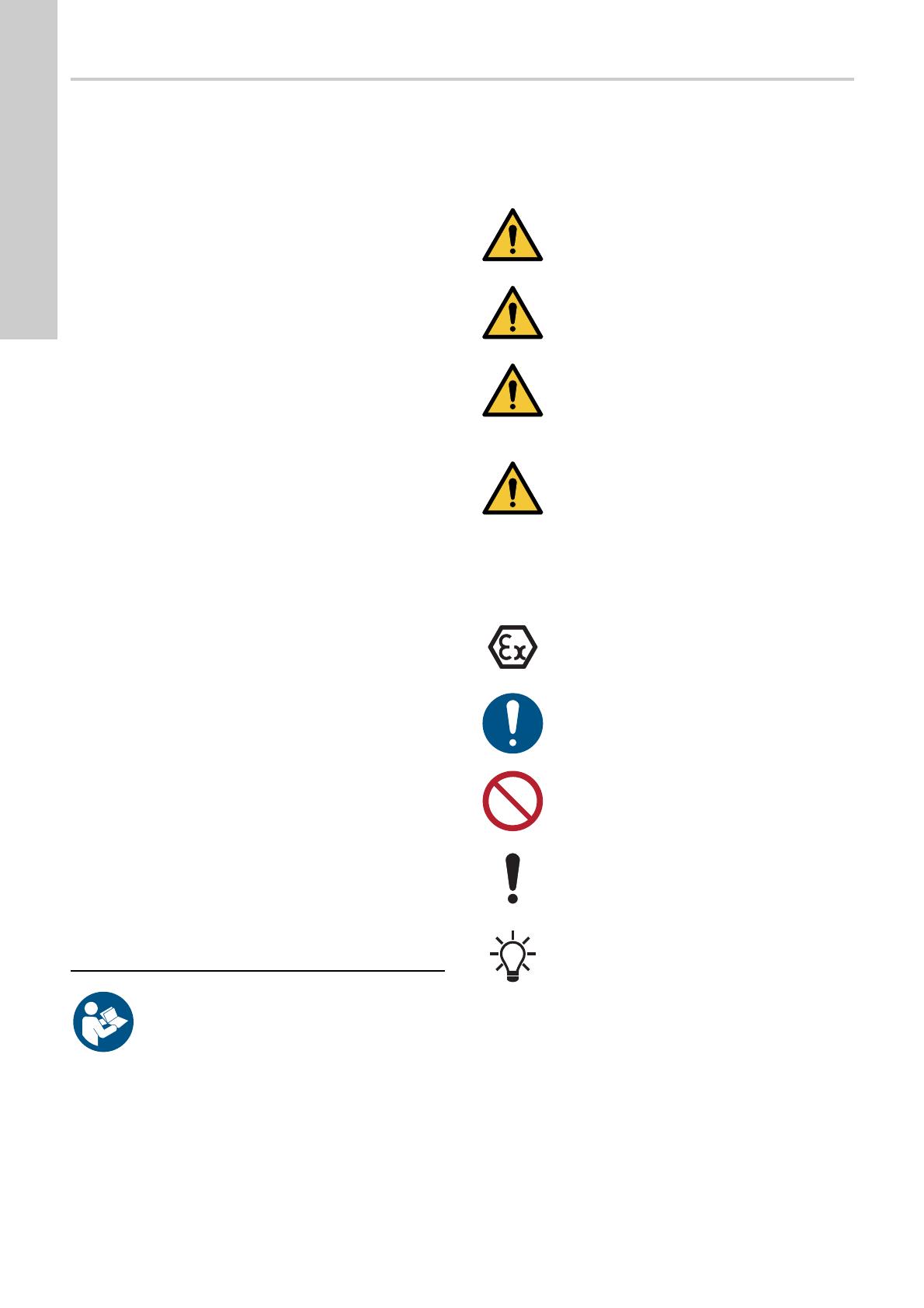
1.1 Hazard statements
The symbols and hazard statements below may appear in
Grundfos installation and operating instructions, safety
instructions and service instructions.
The hazard statements are structured in the following way:
1.2 Notes
The symbols and notes below may appear in Grundfos
installation and operating instructions, safety instructions and
service instructions.
1. General information
2
1.1 Hazard statements
2
1.2 Notes
2
2. Receiving the product
3
2.1 Transporting the product
3
2.2 Inspecting the product
3
3. Installing the product
3
3.1 Reading guide
3
3.2 Foundation
3
3.3 Mechanical installation
3
3.4 Electrical installation
9
4. Commissioning the product
11
4.1 Checking the power supply
11
4.2 BMS hs pump
12
4.3 BMS hp pump
13
4.4 BMST system
14
4.5 BMSX system
14
4.6 Low-pressure flow control
16
5. Handling and storing the product
17
6. Product introduction
17
6.1 Nameplate
17
6.2 Pumped liquids
17
6.3 Filtration
17
6.4 Flushing and salinity
17
7. Servicing the product
18
7.1 Motor bearings
18
7.2 Preventive maintenance
18
8. Starting up the product after standstill
19
8.1 Frequency of starts and stops
19
9. Taking the product out of operation
19
9.1 BMS hs pump
19
9.2 BMS hp pump
20
9.3 BMST system
20
9.4 BMSX system
21
9.5 Flushing
21
10. Fault finding the product
22
10.1 BMS hs and BMST
22
10.2 BMS hp
23
10.3 Pressure exchanger of BMSX
24
11. Technical data
25
12. Disposing of the product
25
Read this document before installing the product.
Installation and operation must comply with local
regulations and accepted codes of good practice.
DANGER
Indicates a hazardous situation which, if not avoided,
will result in death or serious personal injury.
WARNING
Indicates a hazardous situation which, if not avoided,
could result in death or serious personal injury.
CAUTION
Indicates a hazardous situation which, if not avoided,
could result in minor or moderate personal injury.
SIGNAL WORD
Description of hazard
Consequence of ignoring the warning.
- Action to avoid the hazard.
Observe these instructions for explosion-proof
products.
A blue or grey circle with a white graphical symbol
indicates that an action must be taken.
A red or grey circle with a diagonal bar, possibly with
a black graphical symbol, indicates that an action
must not be taken or must be stopped.
If these instructions are not observed, it may result in
malfunction or damage to the equipment.
Tips and advice that make the work easier.


