Page is loading ...


Table of Contents
Safety 4
Safety Precautions 4
Introduction 5
Using this Document 5
Viewing the Document Electronically 5
Printing the Document 5
Product Overview 6
Product Overview 6
Selector Panel 6
Electric valve 7
Installation 10
Installation Overview 10
Preparing for the Installation 10
Modifying the Equipment 10
Determining the Electric Valve Location 10
Determining the Selector Panel Location 10
Determining Hose Routing 10
Determining Cable Routing 10
Dimensions—Control Panel 11
Dimensions—Electric Valve 12
Dimensions—1-1/2 Inch NPT 2 Inch Victaulic Flowmeter Tee 13
Electronic and Plumbing Connections 14
Following Best Practices 16
Installing and Connecting the Electric Valve 17
Installing the High Pressure Flowmeter Tee 18
Installing the Hoses 20
Programming the Selector Panel 21
Operation 22
Operating the Selector Panel 22
Selecting the Output 22
After Operation 22
Flushing the System 22
Draining the System 22
Service Parts 23

Safety Introduction Product Overview Installation Oper ation Service Parts
4 | 24
Safety Precautions
• Read and understand all associated documentation before you begin the
installation.
• Read and understand all the notices and safety precautions.
• Be aware that these instructions are only guidelines and are not meant to be
denitive. Contact Waterous when you have questions about installing, or
operating the equipment.
• Do not install the equipment if you are not familiar with the tools and skills
needed to safely perform required procedures—proper installation is the
responsibility of the purchaser.
• Do not operate any equipment when safety guards are removed.
• Do not modify the equipment
• Regularly check for leaks, worn, or deteriorated parts.
NOTICE
Modifying the equipment
can damage components
and void your warranty.
•
Do not modify the system
or any of its components.
•
Modification
NOTICE
Before Operation
• Read and understand all
the instructions provided.
• Check all fluid levels
and replenish if necessary.
• Remove the all shipping
plugs and install the
operation plugs or caps.
Drain the pump after use
and before servicing.
Liquid ejected at high
pressure can cause
serious injury.
High Pressure
•
•

5 | 24
Safety Introduction Product Overview Installation Oper ation Service Parts
Use this document to install, operate, and maintain your Waterous equipment.
Understand the following conditions before continuing with the document:
• The instructions may refer to options or equipment that you may not have
purchased with your system.
• The illustrations in this document are intended to convey concepts. Do
not use the illustrations to determine physical attributes, placement, or
proportion.
• Any equipment described in this document is intended to be installed by a
person or persons with the necessary skills and knowledge to perform the
installation.
• Any equipment described in this document is intended to be operated by a
person or persons with the basic knowledge of operating similar equipment.
This document is divided into the following sections:
Safety
This section describes general precautions and alert symbols that are in this
document.
Introduction
This section is an overview of the document.
Product Overview
This section describes the components that make-up the system.
Installation
This section describes the installation and initial setup procedures.
Oper ation
This section describes the equipment operation.
Service Parts
This section describes the service parts.
Using this Document
Use the guidelines below when viewing this document.
Viewing the Document Electronically
• View this document in landscape orientation.
• Use the table of contents to navigate directly to that section.
• Text with this appearance is linked to a reference.
Printing the Document
• The document is viewed the best when printed in color.
• The print on both sides and ip on long edge features can provide the
best results.
• Use a 3-ring binder to store the document.

6 | 24
Safety Introduction Product Overview Installation Oper ation Service Parts
Product Overview
The dual foam injection kit adds foam injection capability to a second waterway in your apparatus. In typical applications, it creates a high pressure/low volume
output that supplements an existing low pressure/high volume output. During operation, high or low pressure port injection is selected though the foam injection
selector.
Selector Panel
35
2
1
4
Figure 1
Feature Description
1Mounting hole This secures the panel to the apparatus.
2 Low pressure LED This indicates the low pressure is enabled.
3Low pressure button This activates the low pressure injector.
4 High pressure LED This indicates the high pressure is enabled.
5 High pressure button This activates the high pressure injector.
7
9
6
8
Figure 2
Feature Description
6 High pressure connector This connects to the high pressure owmeter.
7 Flow sensor connector This connects to the foam pump control box.
8 Low pressure connector This connects to the low pressure owmeter.
9 Electric valve connector This connects to the electric valve.

7 | 24
Safety Introduction Product Overview Installation Oper ation Service Parts
Electric valve
3
6
5
2
1
4
Figure 3
Feature Description
1Valve wire harness This connects the valve to the selector panel.
2 Low pressure port This port is connected to the low pressure injector.
3 Concentrate supply port This port is connected to the foam proportioner.
4Electric valve actuator This operates the valve.
5Mounting bracket This mounts the valve to the apparatus.
6High pressure port This port is connected to the high pressure injector.

8 | 24
Safety Introduction Product Overview Installation Oper ation Service Parts
Flowmeter
Figure 4
Feature Description
1Flowmeter This measures the ow in the waterway.
2Tee inlet/outlet This connects as an inlet or outlet in the waterway.
3Flowmeter cable This connects the owmeter to the control panel.
4Tee inlet/outlet This connects as an inlet or outlet in the waterway.
5Flowmeter tee This is the tting that houses the owmeter.
2
5
4
1
3

9 | 24
Safety Introduction Product Overview Installation Oper ation Service Parts
Check Valve and Wiring Harnesses
Figure 5
Feature Description
1Check valve This is installed to the injector tting to prevent concentrate back ow.
2Wire harness—valve connector This plugs into the electric valve wire harness.
3 Extension cable—5-pin male connector This plugs into the foam pump control box.
4 Wire harness—power connector This plugs into the apparatus power source.
5 Wire harness—control connector This plugs into the control panel.
6 Extension cable—5-pin female connector This plugs into the control panel.
36
5
2
1
4
3 ft (10 m)
3 ft (10 m)

10 | 24
Safety Introduction Product Overview Installation Oper ation Service Parts
Installation Overview
This equipment is intended to be installed by a person or persons with the basic
knowledge of installing similar equipment. Contact Waterous with questions
about installing the equipment. The installation may require the following tasks
and abilities:
• Locating, drilling, and cutting
features into the apparatus
• Connecting hoses and ttings
• Routing and securing hoses
• Routing and securing wiring
• Programming and nal testing
Preparing for the Installation
Read and understand the installation instructions before installing the
equipment. Prepare a suitable, well-lit area, and gather all the necessary tools
before you install the equipment.
Modifying the Equipment
This equipment is intended to operate as designed. Do not remove, modify, or
change the components in the system. Doing so will void the warranty. Contact
Waterous for more information.
NOTICE
Modifying the equipment
can damage components
and void your warranty.
•
Do not modify the system
or any of its components.
•
Modification
Do not modify the system or any components. Doing so will void your
warranty.
Determining the Electric Valve Location
Use the following guidelines to determine a location to mount the electric valve:
• Consider the hose and cable routing.
• Consider accessibility for maintenance.
• Install the electric valve where it has minimal exposure to excessive dirt, road
debris, and heat buildup.
Determining the Selector Panel Location
Use the following guidelines to determine a location to mount the control panel:
• Consider the cable and wire harness routing.
• Consider accessibility for maintenance.
• A minimum space of 5 inches (127 mm) behind the panel is recommended to
allow an adequate cable bend radius.
Determining Hose Routing
Use the following guidelines when routing the hoses:
• Route the hose in a straight line whenever possible.
• Do not pinch or kink the hose.
• Do not secure the hose to moving parts.
• Do not secure the hose near excessive heat.
Determining Cable Routing
Use the following guidelines when routing the cables and wire harnesses:
• Route the cable in a straight line whenever possible.
• Allow room for an adequate bend radius.
• Do not secure the cables or wire harness to moving parts.
• Do not secure the cables or wire harness near excessive heat.


14 | 24
Safety Introduction Product Overview Installation Oper ation Service Parts
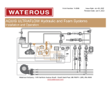
Electronic and Plumbing Connections
Note: The illustrations are intended to convey concept to guide you through the installation. Your application may differ visually from the illustration. Contact
Waterous for more information.
Figure 9
3 5 6 10
9
11
4
21
18
21
20
19
22
12
13
14
16
15
17
8
7

15 | 24
Safety Introduction Product Overview Installation Oper ation Service Parts
Electronic and Plumbing Connections
Feature Description
1 High pressure check valve This check valve is installed on the high pressure foam injector. It prevents concentrate back ow.
2Flowmeter tee This measures the ow in the waterway.
3Waterway This is the plumbing in the apparatus that ows water or solution to the hoses.
4 Electric valve connector This connector plugs into the selector panel wire harness connector.
5 Control panel wire harness connector This connector plugs into the electric valve connector.
6 Electric valve wire harness—10 ft (3 m) This wire harness connects the valve to the selector panel and power supply.
7 Flowmeter extension cables—10 ft (3 m) This cable or cables connect the high pressure owmeter to the selector panel.
8High pressure owmeter connector This is the high pressure owmeter connector on the selector panel.
9 Electric valve connector This is the electric valve wire harness connector on the selector panel.
10 Electric valve wire harness connector This connector plugs the electric valve wire harness connector on the selector panel.
11 Power supply to electric valve connector This connector plugs into the apparatus power connector that is provided by the manufacturer.
12 Foam pump cable—10 ft (3 m) This cable connects the foam pump to the selector panel and provides power to the selector panel.
13 Foam pump connector This is the foam pump connector on the selector panel
14 Low pressure owmeter connector This is the low pressure ow meter connector on the selector panel.
15 Foam injection selector panel This controls the electric valve.
16 Low pressure owmeter connector This connector plugs into the low pressure connector on to the selector panel.
17 Existing components These components are part of the existing concentrate injection system—Not included with the kit.
18 High pressure concentrate supply This port supplies concentrate to the high pressure injector.
19 Electric valve This routes the concentrate between 2 ports.
20 Concentrate from foam pump This port is connected to the foam pump output.
21 Low pressure concentrate supply This port supplies concentrate to the low pressure injector.
22 Low pressure check valve This check valve is installed on the low pressure foam injector. It prevents concentrate back ow.

16 | 24
Safety Introduction Product Overview Installation Oper ation Service Parts
Following Best Practices
Top
Drain the lines before
servicing.
Liquid ejected at high
pressure can cause
serious injury.
High Pressure
•
•
1 4
5
6
2
3
Use the illustrations to guide you to a successful
install. Use industry best practices and common
sense when you install the components. Contact
Waterous for more information.
1 Do not create a small bend radius. Use the
following formula as a guide:
cable diameter X 10 = bend radius
Example: A cable diameter of 0.25 inch (6.35
mm) has a minimum bend radius of 2-1/2
inches (63.5 mm).
2 Use cable ties, or similar, to secure the cables
and wire harnesses.
• Do not secure the cables or wire harness to
moving parts.
• Do not secure the cables or wire harness
near excessive heat.
• Do not secure data and signal wires with
power wires.
3Locate the pin identier to determine pin
locations.
4Installing or operating the owmeter at an
angle greater than 15˚ causes inaccurate
readings.
5 Flowmeter coupling—Installer supplied 2 inch
victaulic, or 1-1/2 inch NPT connector.
6 Drain the lines to relieve pressure before
servicing.

17 | 24
Safety Introduction Product Overview Installation Oper ation Service Parts
Installing and Connecting the Electric Valve
Page 12
2
3
14
910
5 6 Page 16
11 12
Page 11
7 8
Use the illustrations to install the valve assembly
and connect the wire harness to the selector panel
and power supply. Refer to: "Electronic and
Plumbing Connections" on page 14 for more
information.
1 Valve assembly
2Mounting hardware—Installer supplied
3Mounting location
4 Mounting holes—Installer located and drilled.
Refer to: "Determining the Electric Valve
Location" on page 10 and Figure 7
5 Control panel wire harness connector
6 Electric valve connector
7 Mounting holes—Installer located and drilled.
Refer to: "Determining the Selector Panel
Location" on page 10 and "Figure 6" on
page 11
8 Panel cutout—Installer located and cut.
Refer to: "Determining the Selector Panel
Location" on page 10 and "Figure 6" on
page 11
9 Electric valve wire harness connector
10 Electric valve connector
11 Power supply to electric valve connector
12 Power supply connector—Installer supplied
Deutsch DT06-2S. Refer to: "Following Best
Practices" on page 16.
Pin outs:
• Pin 1=+12 V or +24 V
• Pin 2=ground

18 | 24
Safety Introduction Product Overview Installation Oper ation Service Parts
Installing the High Pressure Flowmeter Tee
21 3
Page 16
9
8
54
11
10
7
6
Use the illustrations to install the owmeter tee
into the waterway and to connect the new and
existing owmeter to the selector panel. Refer to:
"Electronic and Plumbing Connections" on
page 14 for more information.
1 Output connector—Installer supplied. Refer to:
"Following Best Practices" on page 16.
2Flowmeter Tee
3 Input connector—Installer supplied. Refer to:
"Following Best Practices" on page 16.
4Cable from owmeter
5 Extension cable
6Extension cable—Connected to owmeter
7High pressure owmeter connector
8 Foam pump connector
9 Existing cable from foam pump control box.
10 Low pressure owmeter connector
11 Existing cable from existing owmeter.

19 | 24
Safety Introduction Product Overview Installation Oper ation Service Parts
Installing the High Pressure Flowmeter Tee—Continued
1
2
Page 16
3
4
Use the illustrations to complete the high pressure
owmeter tee installation.
1 Route the wiring. Refer to: "Following Best
Practices" on page 16.
2 Use a cable tie or similar to secure the wires to
the apparatus.
3Selector panel bezel.
4 Use the appropriate hardware to secure the
panel to the apparatus—Installer supplied.

20 | 24
Safety Introduction Product Overview Installation Oper ation Service Parts
Installing the Hoses
3
1 2
Page 14
7
8
5 6
4
12
11
9
10
13
Use the illustrations to install the concentrate
check valve and hose lines. Refer to: "Electronic
and Plumbing Connections" on page 14 for
more information. Locally source hoses and ttings
that are appropriate for your application to connect
the electric valve to the foam concentrate injectors.
1 3/8 inch inner hose diameter—AQUIS 1.5 and
3.0 foam pump.
2 1/2 inch inner hose diameter—AQUIS 6.0 foam
pump.
3 Minimum pressure rating—450 psi (31 bar)
4Electric Valve
5 Foam concentrate hose—Installer provided
hose connecting the high pressure supply port
to the foam concentrate check valve.
6 High pressure waterway check valve
7 High pressure foam concentrate check valve
8 High pressure foam concentrate injector—
Installer provided.
9 Foam concentrate hose—Installer provided
hose connecting the low supply port to the low
pressure foam concentrate check valve.
10 Low pressure foam concentrate check valve—
Existing or installer provided.
11 Low pressure foam concentrate injector—
Existing or installer provided.
12 Low pressure waterway check valve—Existing
or installer provided waterway check valve or
manifold.
13 Foam concentrate supply hose—Installer
provided hose connecting the foam pump
output and the electric valve input.
/