Page is loading ...

A7VA Series Motherboard
User’s Manual

Statement:
This manual is the intellectual property of Foxconn, Inc. Although the information
itself to inform the user of these changes.
Trademark:
All trademarks are the property of their respective owners.
Version:
User’s Manual V1.0 for A7VA Series motherboard.
Symbol description:
Caution : refers to important information that can help you to use motherboard
better, and tells you how to avoid problems.
Warning : indicating a potential risk of hardware damage or physical injury
may exist.
WEEE:
The use of this symbol indicates that this product may not be treated as household
waste. By ensuring this product is disposed of correctly, you will help prevent potential
negative consequences for the environment and human health, which could other-
wise be caused by inappropriate waste handling of this product. For more detailed
household waste disposal service or the shop where you purchased this product.
More information:
If you want more information about our products, please visit Foxconn’s
website: http://www.foxconnchannel.com
C
A
U
T
I
O
N
!
© All rights reserved.
All trade names are registered trademarks of respective manufacturers listed.
W
A
R
N
I
N
G
!

Declaration of conformity
HON HAI PRECISION INDUSTRY COMPANY LTD
66 , CHUNG SHAN RD., TU-CHENG INDUSTRIAL DISTRICT,
TAIPEI HSIEN, TAIWAN, R.O.C.
declares that the product
Motherboard A7VA-S/A7VA
is in conformity with
accordance with 89/336 EEC-EMC Directive)
disturbance characteristics of information technology
equipment
Part 3: Limits
Section 2: Limits for harmonic current emissions
(equipment input current <= 16A per phase)
Part 3: Limits
voltage supply systems for equipment with rated current
<= 16A
characteristics limits and methods of measurement
Signature : Place / Date : TAIPEI/2008
Printed Name : James Liang

Declaration of conformity
Trade Name: FOXCONN
Model Name: A7VA-S/A7VA
Responsible Party: PCE Industry Inc.
Type of Product: Motherboard
Manufacturer: HON HAI PRECISION INDUSTRY
COMPANY LTD
Address: 66 , CHUNG SHAN RD., TU-CHENG
INDUSTRIAL DISTRICT, TAIPEI HSIEN,
TAIWAN, R.O.C.
Supplementary Information:
two conditions : (1) this device may not cause harmful interference, and (2) this device
must accept any interference received, including interference that may cause undesired
operation.
Tested to comply with FCC standards.
Signature : Date : 2008

Installation Precautions
Please carefully read the following procedures to install your computer :
to the motherboard and CPU due to high temperature. Never turn on the
computer if the CPU fan is not properly installed.
CPU is overclocked. Normal operation depends on the overclocking capac-
ity of your device.
cables to the internal connectors on the motherboard, make sure their
pinouts are matching with the connectors on the motherboard. Incorrect con-
nections might damage the motherboard.
-
tors.
with the motherboard circuit or its components. Also, make sure there are no
leftover screws or metal components placed on the motherboard or within the
computer casing.
C
A
U
T
I
O
N
!
comes out as a spark which will quickly damage your electronic equipment.
Please wear an electrostatic discharge (ESD) wrist strap when handling
components such as a motherboard, CPU or memory.
CPU, memory, expansion cards or other peripherals. It is recommended to
unplug the AC power cord from the power supply outlet. Failure to unplug
the power supply cord may result in serious damage to your system.
W
A
R
N
I
N
G
!

TABLE OF CONTENTS
Chapter 1 Product Introduction
..............................................................................2
Layout.......................................................................................................
Back Panel Connectors ............................................................................
Chapter 2 Hardware Install
Install the CPU and CPU Cooler ..............................................................8
Install the Memory ..................................................................................10
Install an Expansion Card ......................................................................12
Install other Internal Connectors ............................................................13
Jumpers ..................................................................................................17
Chapter 3 BIOS Setup
Enter BIOS Setup ...................................................................................19
Main Menu..............................................................................................19
System Information ................................................................................21
Advanced BIOS Features.......................................................................23
Fox Central Control Unit .........................................................................
Advanced Chipset FeaturesAdvanced Chipset Features ...................................................................30
Integrated Peripherals ............................................................................
Power Management Setup .....................................................................38
PC Health Status ....................................................................................
BIOS Security Features..........................................................................
Load Optimal DefaultsOptimal DefaultsDefaults ............................................................................
Save & Exit Setup ..................................................................................
Exit Without Saving ................................................................................
Chapter 4 CD Instruction
Utility CD contentUtility CD content....................................................................................
Install driver and utility ............................................................................
FOX ONE
Main Page ........................................................................................
CPU Control .....................................................................................
Frequency Control ............................................................................
Limit Setting......................................................................................
Voltage Control .................................................................................
Fan Control.......................................................................................
FOX LiveUpdate
Local Update ....................................................................................
Online Update ..................................................................................60

.........................................................................................63
About & Help ....................................................................................
FOX LOGO .............................................................................................66
FOX DMI ................................................................................................67
Chapter 5 RAID Conguration
.............................................................70
FastBuild Driver ......................................................................................72
Create a RAID Driver Diskette ...............................................................
RAID Enable in BIOS .............................................................................76
Select a RAID Array for Use ...................................................................76
Install a New Windows XP .....................................................................89
Setting Up a Non-Bootable RAID Array..................................................93
Technical Support :
Website :
http://www.foxconnchannel.com
Support Website :
http://www.foxconnsupport.com
Worldwide online contact Support :
http://www.foxconnchannel.com/support/online.aspx
CPU, Memory, VGA Compatibility Supporting Website :
http://www.foxconnchannel.com/product/Motherboards/compatibility.aspx
Support

Thank you for buying Foxconn A7VA Series motherboard. Foxconn
products are engineered to maximize computing power, providing
only what you need for break-through performance.
With advanced overclocking capability and a range of connectivity
features for today multi-media computing requirements, A7VA-S/
A7VA enables you to unleash more power from your computer.
This chapter includes the following information:

1
2
1-1 Product Specications
CPU Support AMD socket AM2+ PhenomPhenom
TM
FX
/ PhenomPhenom
TM
series processorsseries processors
Support AMD socket AM2 series processors :Support AMD socket AM2 series processors :
AthlonAthlon
TM
TM
X2 Dual-Core /
Athlon
TM
TM
HyperTransport 2000/1600MT/s for AM2 CPU
Chipset North Bridge: AMD 780V
South Bridge: AMDSouth Bridge: AMD SB700
Support up to 8GB of system memory
*DDR2 1066 is only supported by some AM2+ CPU
Audio Realtek 8-channel audio chip
Support for S/PDIF Out
Support Jack-Sensing function
LAN Realtek 10/100/1000Mb/s LAN chip10/100/1000Mb/s LAN chip chip
Expansion Slots 1 x PCI Express x16 slot
2 x PCI Express x1 slots
3 x PCI slots
Onboard Serial ATA 6 x SATA connectors
300MB/s data transfer rate
Support hot plug and NCQ (Native Command Queuing )
USB Support hot plug
Support up to 12 x USB 2.0 ports (6 rear panel ports, 3 onboard USB
headers supporting 6 extra ports)
1 x 8-pin ATX 12V power connector
1 x Floppy disk drive connector
1 x IDE connector
6 x SATA connectors
3 x USB 2.0 connectors (supporting 6connectors (supporting 6 (supporting 6 x USB devices)
1 x NB fan header (3-pin)
1 x Front panel connectorconnector
1 x CD_IN connector
1 x Front Audio connectorconnector
1 x IR connectorIR connector connectorconnector
1 x Chassis intrusion alarm header (INTR)header (INTR) (INTR)
1 x S/PDIF_OUT connectorconnector

1
3
1 x Speaker connector
Back Panel 1 x PS/2 keyboard port
Connectors 1 x PS/2 mouse port
1 x VGA port
1 x Serial port1 x Serial portSerial port port
1 x DVI-D port
6 x USB 2.0 ports
8-channel Audio ports
Hardware Monitor System voltage detection
CPU/System temperature detection
CPU/System fan speed detection
CPU overheating warning
CPU/System fan speed control/System fan speed control fan speed control
Low power consumption and power management features
PCI Express x16 Support 8GB/s (16GB/s concurrent) bandwidth
Low power consumption and power management features
Bundled Software FOX ONE
FOX LiveUpdate
FOX LOGO
FOX DMI
Operating System Support for Microsoft
®
Windows
®
Vista/XP only
The chipset driver of this motherboard does not support Windows
®
2000.
C
A
U
TI
O
N
!

1
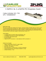
1-2 Layout
1. 8-pin ATX 12V Power Connector
2. NB_FAN Header
3. PCI Express x1 Slots
6. CD_IN Connector
7. Front Audio Connector
8. S/PDIF_OUT Connector
9. Front USB Connectors
10. Clear CMOS Jumper
11. South Bridge: AMD SB700
12. Front Panel Connector
13. Speaker Connector
16. IrDA Connector
17. Chassis Intrusion Alarm Header
18. System Fan Header
20. IDE Connector
21. DDR2 DIMM Slots
22. North Bridge: AMD 780V
23. CPU_FAN Header
Note : The above motherboard layout is for reference only, please refer to the physical mother-
board for detail.
171615 19181312
1
2
3
5
4
6
8
9
11
10
7
20
23
21
22
14
24

1
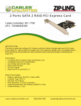
1-3 Back Panel Connectors
1. PS/2 Mouse Port
Use the upper port (green) to connect a PS/2 mouse.
2. PS/2 Keyboard Port
Use the lower port (purple) to connect a PS/2 keyboard.
3. Serial Port
This is output of RS232 COM1 port.
4. VGA Port
To connect with external display devices, such as monitor or LCD display.
5. DVI-D Port
to this port.
6. USB Port
7. Audio Ports
USB Ports
LAN PortVGA Port Port
PS/2 Keyboard
Port
PS/2 Mouse Port
6
1
DVI-D Port Audio Ports
Line Out
Microphone
Subwoofer
Rear Speaker
Side Speaker
Line In
8
Serial Port
5
2
4
7
3
Port 2-channel 7.1-channel
Blue Line In Line In Line In Line In
Green Line Out Front Speaker Out Front Speaker Out Front Speaker Out
Pink Microphone In Microphone In Microphone In Microphone In
Orange - - Center/Subwoofer Out Center/Subwoofer Out
Black - Rear Speaker Out Rear Speaker Out Rear Speaker Out
Grey - - - Side Speaker Out

1
6
8. RJ-45 LAN Port
The Ethernet LAN port provides Internet connection at up to 10/100/1000Mb/s data rate.
LAN Type
Left: Active Right: Link
Status Description Status Description
1000M
Off No Link Off No Link
Green
Blinking
Data Activity
Off 10Mb/s Connection
Green 100Mb/s Connection
Orange 1000Mb/s Connection
Link
LED
Active
LED

Please visit this website for more supporting information about CPU, Memory and
VGA for your motherboard :
http://www.foxconnchannel.com/product/Motherboards/compatibility.aspx
This chapter introduces the hardware installation process, including
the installation of the CPU, memory, power supply, slots, pin headers
and the mounting of jumpers. Caution should be exercised during
the installation of these modules. Please refer to the motherboard
layout prior to any installation and read the contents in this chapter
carefully.
This chapter includes the following information :

2
8
2-1 Install the CPU and CPU Cooler
Install the CPU
Locate the Pin-1 CPU triangle mark and the Pin-1 of the CPU socket.
Pin-1 triangle
marking of CPU
Pin-1 corner of the
CPU socket
1. Release the CPU socket lever.Release the CPU socket lever.
2. Align Pin-1 of the CPU with the CPU
socket, and gently put the CPU
onto the socket.
Read the following guidelines before you begin to install the CPU :
installing the CPU to prevent hardware damage.
and damage of the CPU may occur.
since it does not meet the standard requirements for the peripherals. If you want to
C
A
UTI
O
N
!

2
9
3. When CPU is properly seated,
push the CPU socket lever back
to its locked position.
Install the CPU Cooler
Follow the steps below to correctly install the CPU cooler. (The following procedures use Foxconn
cooler as the example.)
1. Apply and spread an even thermal
grease on the surface of CPU.
2.
side of the stand.
3. Buckle the heatsink at another
side, and press the fasten lever
down to tightly seat the cooler.
connector to the CPU fan header
on the motherboard .
Use extreme care when removing the CPU cooler because the thermal grease may
adhere to the CPU. Inadequately removing the CPU cooler may damage the CPU.
C
A
U
T
I
O
N
!

2
10
2-2 Install the Memory
Dual Channel Memory Conguration
This motherboard provides four DDR2 memory sockets and supports Dual Channel Technology.
When memory is installed, the BIOS will automatically check the memory in your system.
Four DDR2 memory sockets are divided into two channels :
Channel 0 : DIMM1, DIMM3
The combinations of DIMM modules are :
It is recommended that memory of the same capacity, brand, speed, and chips be
C
A
U
T
I
O
N
!
Read the following guidelines before you begin to install the memory :
of the same capacity, brand, speed, and chips be used.
installing the memory to prevent hardware damage.
one direction. If you are unable to insert the memory, switch the direction.
C
A
U
T
IO
N
!
DIMM1 DIMM2 DIMM3
Single Channel DS/SS - - -
Single Channel DS/SS - DS/SS -
Single Channel - DS/SS - -
Single Channel - DS/SS - DS/SS
Dual Channel DS/SS DS/SS - -
Dual Channel - - DS/SS DS/SS
Dual Channel DS/SS DS/SS DS/SS DS/SS
(DS : Dual Side, SS : Single Side, - : No Memory)

2
11
Installing a Memory
If you take a look at front side of memory module, it has asymmetric pin counts on both sides separated
your memory modules into the sockets.
Step 1:
Spread the clips at both ends of the memory socket.
Place the memory module onto the socket, then put
socket.
Step 2:
The clips at both ends of the socket will snap into place
when the memory module is securely inserted.
Before installing a memory module, make sure to turn off the computer and unplug the
power cord from the power outlet to prevent damage to the memory module. Be sure
to install DDR2 DIMMs on this motherboard.
C
A
U
T
I
O
N
!
112-Pin128-Pin
Notch

2
12
2-3 Install an Expansion Card
Follow the steps below to correctly install your expansion card in the expansion slot.
1. Locate an expansion slot that supports your card. Remove the metal slot cover from the chassis
back panel.
2. Align the card with the slot, and press down on the card until it is fully seated in the slot.
3. Make sure the metal contacts on the card are completely inserted into the slot.
6. Turn on your computer. If necessary, go to BIOS Setup to make any required BIOS changes for
your expansion card(s).
7. Install the driver provided with the expansion card in your operating system.
Installing and Removing a PCI Express x16 Graphics Card :
• Installing a Graphics Card:
Gently insert the graphics card into the PCI Express x16 slot.
Make sure the graphics card is locked by the latch at the end of
the PCI Express x16 slot.
• Removing the Card:
Push the latch at the end of the PCI Express x16 slot to release
the card and then pull the card straight up from the slot.
PCI
PCI Express x1
PCI Express x16
that came with your expansion card.
installing an expansion card to prevent hardware damage.
C
A
U
T
I
O
N
!

2
13
2-4 Install other Internal Connectors
Power Connectors
This motherboard uses an ATX power supply. In order not to damage any device, make sure all the
devices have been installed properly before applying the power supply.
24-pin ATX power connector : PWR1
PWR1 is the ATX power supply connector. Make sure that the power supply cable and pins are
properly aligned with the connector on the motherboard. Firmly plug the power supply cable into the
connector and make sure it is secure.
8-pin ATX 12 V Power Connector : PWR2
The 8-pin ATX 12V power supply connects to PWR2 and provides power to the CPU.
If you are using a 20-pin power supply, you need
to align the ATX power connector according to
the picture.
C
A
U
T
I
O
N
!
20-Pin Power
Pin # Pin #
1 3.3V 13 3.3V
2 3.3V -12V
3 GND GND
16 PS_ON(Soft On/Off)
GND 17 GND
6 18 GND
7 GND 19 GND
8 Power Good 20 NC
9 21
10 +12V 22
11 +12V 23
12 3.3V GND
PWR1
13
12
1
Pin # Pin #
1 GND +12V
2 GND 6 +12V
3 GND 7 +12V
GND 8 +12V
1
8
PWR2
GND
+12V
/