Page is loading ...

INSTALLATION INSTRUCTIONS
CU-3KE19NBU
CU-4KE24NBU
CU-4KE31NBU
(852-6-4190-584-00-2)
APPENDIX A
A-1

For Outdoor Unit
This air conditioner uses the refrigerant R410A.
External diameter of service port R410A: 5/16"
Split System Air Conditioner
85264190584002 2011 CV6233187853
INSTALLATION INSTRUCTIONS
NOTE
Contents
Page
IMPORTANT!
Please Read Before Starting .................................. 2
1. GENERAL .......................................................... 4
1-1. Tools Required for Installation (not supplied)
1-2. Accessories Supplied with Unit
1-3. Optional Copper Tubing Kit
1-4. Type of Copper Tube and Insulation Material
1-5. Additional Materials Required for Installation
2. INSTALLATION SITE SELECTION ................... 5
2-1. Indoor Unit
2-2. Connecting Indoor Units
2-3. Outdoor Unit
2-4. Baffle Plate for the Outdoor Unit
2-5. Outer Dimensions of Outdoor Unit
2-6. Diagram of Outdoor Unit Installation
3. INSTALLATION PROCESS .............................. 16
3-1. Embedding the Tubing and Wiring
3-2. Use of the Flaring Method
3-3. Flaring Procedure with a Flare Tool
3-4. Caution before Connecting Tubes Tightly
3-5. Tubing Connections
3-6. Insulation of Refrigerant Tubing
3-7. Taping the Tubes
3-8. Finishing the Installation
4. AIR PURGING................................................... 19
Air Purging with a Vacuum Pump (for Test Run)
Pump Down
5. WIRING INSTRUCTIONS ................................ 22
5-1. General Precautions on Wiring
5-2. Recommended Wire Length and Diameter
5-3. Wiring System Diagram
5-4. How to Connect Wiring to the Terminal
5-5. Wiring Instructions for the Outdoor Unit
6. TEST RUN......................................................... 26
7. CONNECTING A HOME AUTOMATION
DEVICE ............................................................. 27
8. INSTALLATION CHECK SHEET ...................... 27
Indoor unit A
Indoor unit B
Indoor unit C
Indoor unit D
Outdoor unit
Combination example
Model Combinations
Combine indoor and outdoor units only as listed
below.
Model No.
Indoor Unit Outdoor Unit
CS-MKE7NKU CU-3KE19NBU
CS-MKE9NKU CU-4KE24NBU
CS-MKE12NKU CU-4KE31NBU
CS-MKE18NKU
CS-MKE24NKU
CS-MKE9NB4U
CS-MKE12NB4U
CS-KE18NB4UW
Power Source:
60 Hz, single-phase, 230 / 208 VAC

IMPORTANT!
Please Read Before Starting
This air conditioning system meets strict safety and operating
standards. As the installer or service person, it is an important
part of your job to install or service the system so it operates
safely and efficiently.
For safe installation and trouble-free operation, you
must:
Carefully read this instruction booklet before beginning.
Follow each installation or repair step exactly as shown.
Observe all local, state, and national electrical codes.
Pay close attention to all warning and caution notices
given in this manual.
This symbol refers to a hazard
or unsafe practice which can
result in severe personal injury
or death.
This symbol refers to a hazard
or unsafe practice which can
result in personal injury or prod-
uct or property damage.
If Necessary, Get Help
These instructions are all you need for most installation
sites and maintenance conditions. If you require help for a
special problem, contact our sales/service outlet or your
certified dealer for additional instructions.
In Case of Improper Installation
The manufacturer shall in no way be responsible for improp-
er installation or maintenance service, including failure to
follow the instructions in this document.
SPECIAL PRECAUTIONS
When Wiring
ELECTRICAL SHOCK CAN CAUSE SEVERE
PERSONAL INJURY OR DEATH. ONLY A
QUALIFIED, EXPERIENCED ELECTRICIAN
SHOULD ATTEMPT TO WIRE THIS SYSTEM.
'RQRWVXSSO\SRZHUWRWKHXQLWXQWLODOOZLULQJDQGWXELQJ
are completed or reconnected and checked.
+LJKO\GDQJHURXVHOHFWULFDOYROWDJHVDUHXVHGLQWKLV
system. Carefully refer to the wiring diagram and these
instructions when wiring. Improper connections and
inadequate grounding can cause accidental injury or
death.
*URXQGWKHXQLW following local electrical codes.
&RQQHFWDOOZLULQJWLJKWO\/RRVHZLULQJPD\FDXVHRYHU
heating at connection points and a possible fire hazard.
7RSUHYHQWSRVVLEOHKD]DUGVIURPLQVXODWLRQIDLOXUH
the unit must be grounded.
When Transporting
Be careful when picking up and moving the indoor and out-
door units. Get a partner to help, and bend your knees when
lifting to reduce strain on your back. Sharp edges or thin alu-
minum fins on the air conditioner can cut your fingers.
When Installing…
Select an installation location which is rigid and strong
enough to support or hold the unit, and select a location for
easy maintenance.
…In a Ceiling or Wall
Make sure the ceiling/wall is strong enough to hold the
unit’s weight. It may be necessary to construct a strong
wood or metal frame to provide added support.
…In a Room
Properly insulate any tubing run inside a room to prevent
“sweating” that can cause dripping and water damage to
walls and floors.
Keep the fire alarm and the air
outlet at least 1.5 m away from
the unit.
…In Moist or Uneven Locations
Use a raised concrete pad or concrete blocks to provide a
solid, level foundation for the outdoor unit. This prevents
water damage and abnormal vibration.
…In an Area with High Winds
Securely anchor the outdoor unit down with bolts and a
metal frame. Provide a suitable air baffle.
…In a Snowy Area
Install the outdoor unit on a raised platform that is higher
than drifting snow. Provide snow vents.
When Connecting Refrigerant Tubing
9HQWLODWHWKHURRPZHOOLQWKHHYHQWWKDWUHIULJHUDQW
gas leaks during the installation. Be careful not to allow
contact of the refrigerant gas with a flame as this will
cause the generation of poisonous gas.
WARNING
2
WARNING
CAUTION
CAUTION
WARNING
:KHQSHUIRUPLQJpiping work
do not mix air except for speci-
fied refrigerant (R410A) in
refrigeration cycle. It causes
capacity down, and risk of
explosion and injury due to
high tension inside the refrige-
rant cycle.
5HIULJHUDQWJDVOHDNDJHPD\
cause fire.
'RQRWDGGRUUHSODFHUHIULJHUDQW
other than specified type.
It may cause product damage,
burst and injury etc.

8VHWKHIODUHPHWKRGIRUFRQQHFWLQJWXELQJ
$SSO\UHIULJHUDQWOXEULFDQWWRWKHPDWFKLQJVXUIDFHVRI
the flare and union tubes before connecting them, then
tighten the nut with a torque wrench for a leak-free
connection.
&KHFNFDUHIXOO\IRUOHDNVEHIRUHVWDUWLQJWKHWHVWUXQ
'RQRWOHDNUHIULJHUDQWZKLOHSLSLQJZRUNIRUDQLQVWDOODWLRQ
or re-installation, and while repairing refrigeration parts.
Handle liquid refrigerant carefully as it may cause frost-
bite.
When Servicing
7XUQWKHSRZHU2)) DWWKHPDLQSRZHUER[PDLQV
before opening the unit to check or repair electrical
parts and wiring.
.HHS\RXUILQJHUVDQGFORWKLQJDZD\IURPDQ\PRYLQJ
parts.
&OHDQXSWKHVLWHDIWHU\RXILQLVKUHPHPEHULQJWRFKHFN
that no metal scraps or bits of wiring have been left inside
the unit being serviced.
Others
9HQWLODWHDQ\HQFORVHGDUHDVZKHQLQVWDOOLQJRUWHVWLQJ
the refrigeration system. Escaped refrigerant gas, on
contact with fire or heat, can produce dangerously
toxic gas.
&RQILUPXSRQFRPSOHWLQJLQVWDOODWLRQWKDWQRUHIULJHUDQW
gas is leaking. If escaped gas comes in contact with a
stove, gas water heater, electric room heater or other heat
source, it can produce dangerously toxic gas.
'RQRWLQVWDOORQO\DVLQJOHLQGRRUXQLW
'RQRWWRXFKWKHDLULQOHWRUWKHVKDUSDOXPLQXP
fins of the outdoor unit. You may get injured.
'RQRWVLWRUVWHSRQWKHXQLW\RXPD\IDOOGRZQ
accidentally.
'RQRWVWLFNDQ\REMHFWLQWRWKH)$1&$6(
You may be injured and the unit may be damaged.
3
CAUTION
The illustrations are based on the typical appearance of
a standard model. Consequently, the shape may differ
from that of the air conditioner that you are installing.
NOTE

4
1-2. Accessories Supplied with Unit
Table 1
1-3. Optional Copper Tubing Kit
Copper tubing for connecting the outdoor unit to the
indoor unit is available in kits which contain the narrow
and wide tubing, fittings and insulation. Consult your
nearest sales outlet or air conditioning workshop.
1-4. Type of Copper Tube and Insulation Material
If you wish to purchase these materials separately from
a local source, you will need:
1. Deoxidized annealed copper tube for refrigerant tub-
ing as detailed in Table 2.
Cut each tube to the appropriate lengths 1' to 1'4"
(30 cm to 40 cm) to dampen vibration between units.
2. Foamed polyethylene insulation for the specified
copper tubes as required to precise length of tubing.
Wall thickness of the insulation should be not less
than 5/16" (8 mm).
3. Use insulated copper wire for field wiring. Wire size
varies with the total length of wiring.
Refer to 5. Wiring Instructions for details.
1. Refrigeration (armored) tape
2. Insulated staples or clamps for connecting wire
(See local codes.)
3. Putty
4. Refrigeration lubricant
5. Clamps or saddles to secure refrigerant tubing
1
Packed in the outdoor unit.
4 each
Labels for inter-unit
cable and tube
Cushion rubber 4
Parts Figure Q’ty Parts Figure Q’ty Parts Figure Q’ty
Reducer
(3/8" 1/2")
CU-3KE19NBU
CU-4KE24NBU
CU-4KE31NBU
2
1
A B C D
Reducer
(1/2" 3/8")
CAUTION
Check local electrical codes
and regulations before
obtaining wire. Also, check
any specified instructions or
limitations.
Model
Narrow Tube Wide Tube
Outer Dia. Thickness Outer Dia. Thickness
CS-MKE7NKU, CS-MKE9NKU, CS-MKE12NKU
1/4" (6.35 mm) 0.0314" (0.8 mm) 3/8" (9.52 mm) 0.0314" (0.8 mm)
CS-MKE18NKU
1/4" (6.35 mm) 0.0314" (0.8 mm) 1/2" (12.70 mm) 0.0314" (0.8 mm)
CS-MKE24NKU
1/4" (6.35 mm) 0.0314" (0.8 mm) 5/8" (15.88 mm) 0.0393" (1.0 mm)
CS-MKE9NB4U, CS-MKE12NB4U
1/4" (6.35 mm) 0.0314" (0.8 mm) 3/8" (9.52 mm) 0.0314" (0.8 mm)
CS-KE18NB4UW
1/4" (6.35 mm) 0.0314" (0.8 mm) 1/2" (12.70 mm) 0.0314" (0.8 mm)
Table 2
1-5. Additional Materials Required for Installation
1. General
This booklet briefly outlines where and how to install the air conditioning system. Please read over the entire set of instruc-
tions for the indoor and outdoor units and make sure all accessory parts listed are with the system before beginning.
If the electric wiring diagram does not appear in this manual, please check for the diagram on the indoor unit.
1-1. Tools Required for Installation (not supplied)
1. Standard screwdriver
2. Phillips head screwdriver
3. Knife or wire stripper
4. Tape measure
5. Carpenter’s level
6. Sabre saw or key hole saw
7. Hacksaw
8. Core bits
9. Hammer
10. Drill
11. Tube cutter
12. Tube flaring tool
13. Torque wrench
14. Adjustable wrench
15. Reamer (for deburring)
16. Vacuum pump (For R410A)
17. Manifold valve

5
2. Installation Site Selection
2-1. Indoor Unit
AVOID:
direct sunlight.
nearby heat sources that may affect performance of the
unit.
areas where leakage of flammable gas may be expected.
placing or allowing any obstructions near the air conditioner
inlet or outlet.
installing in rooms that contain instant-on (rapid-start)
fluorescent lamps. (These may prevent the air conditioner
from receiving signals.)
places where large amounts of oil mist exist.
installing in locations where there are devices that
generate high-frequency emissions.
DO:
select an appropriate position from which every corner of
the room can be uniformly air-conditioned. (High on a wall
is best for wall-mounted types.)
select a location that will hold the weight of the unit.
select a location where tubing and drain hose have the
shortest run to the outside. (Fig. 1)
allow room for operation and maintenance as well as
unrestricted air flow around the unit. (Fig. 2a or 2b)
install the unit within the maximum elevation difference
(H1, H2, H3, H4) above or below the outdoor unit and
within a total tubing length (L1+L2+L3, L1+L2+L3+L4)
from the outdoor unit as detailed in Table 3 and Fig. 3a.
Drain hose
Indoor unit
Outside drainage
Fig. 1
2" (5 cm)
min.
6" (15 cm)
min.
Front View
2" (5 cm)
min.
Fig. 2a
For wall-mounted units
For ceiling-mounted cassette units
INDOOR
UNIT (1)
INDOOR
UNIT (4)
INDOOR
UNIT (3)
INDOOR
UNIT (2)
Tubing length (L1)
L2
L3
L4
H2
H3
H4
OUTDOOR
UNIT
Elevation
difference (H1)
Fig. 3a
WARNING
To prevent abnormal heat generation
and the possibility of fire, do not
place obstacles, enclosures and
grilles in front of or surrounding the
air conditioner in a way that may
block air flow.
Indoor unit
Floor level
Wall
Minimum height
from floor level
5' (1.5 m)
Fig. 3b
$LUGHOLYHU\IURPDFHLOLQJ
mounted cassette unit will
be degraded if the distance
from the floor to the ceiling
is greater than 10 ft. (3 m).
)RUVWDEOHRSHUDWLRQRIWKH
air conditioner, do not install
wall-mounted units less
than 5' (1.5 m) from floor
level. (Fig. 3b)
CAUTION
Fig. 2b
3.3 ft.
(1m)
(1m)
(1m)
3.3 ft.
(1m)
3.3 ft.
3.3 ft.
3.3 ft.
(1m)

6
install the indoor unit more than 3.3' (1 m) away from any
antenna or power lines or connecting wires used for tele-
vision, radio, telephone, security system, or intercom.
Electrical noise from any of these sources may affect
operation.
install in a sturdy manner to avoid increased operating
noise.
Table 3
* If total tubing length becomes 150 to 200 ft. (Max.) or 150 to 230 ft. (Max.), charge additional refrigerant (R410A) by 0.22 oz./ft.
No additional charge of compressor oil is necessary. For more detailed charging information, refer to the Technical & Service Manual.
Max. Max. Allowable Total Limit of Limit of Elevation Required Amount
Allowable Tubing Length Total Tubing Length Difference of Additional
Model Tubing Length at Shipment (L1+L2+L3) or (H1, H2, H3, H4) Refrigerant
Per Unit (L1+L2+L3) or (L1+L2+L3+L4) (ft.) (oz./ft.)*
(ft.) (L1+L2+L3+L4) (ft.)
(ft.)
CU-3KE19NBU 82 150 (L1+L2+L3) 150 (L1+L2+L3) 50 —
CU-4KE24NBU 82 150 (L1+L2+L3+L4) 200 (L1+L2+L3+L4) 50 0.22
CU-4KE31NBU 100 150 (L1+L2+L3+L4) 230 (L1+L2+L3+L4) 50 0.22

7
Fig. 4b
Union 1/2"(12.70
mm
)
1/2"(12.70
mm
)
Flare 3/8"(9.52
mm
)
A joint for connecting tubes of
different sizes
(3/8"(9.52
mm
) 1/2"(12.70
mm
)) Supplied Reducer
1/4"(6.35
mm
)
1/4"(6.35
mm
)
1/4"(6.35
mm
)
C
B
A
Outdoor unit Indoor unit
(CS-MKE7NKU,CS-MKE9NKU,CS-MKE12NKU)
(CS-MKE9NB4U,CS-MKE12NB4U)
(CS-MKE7NKU,CS-MKE9NKU,CS-MKE12NKU)
(CS-MKE9NB4U,CS-MKE12NB4U)
(CS-MKE18NKU)
(CS-KE18NB4UW)
3/8"(9.52
mm
)
3/8"(9.52
mm
)
3/8"(9.52
mm
)
3/8"(9.52
mm
)
3/8"(9.52
mm
)
(A)
Fig. 4c
C
B
A
(CS-MKE7NKU,CS-MKE9NKU,CS-MKE12NKU)
(CS-MKE9NB4U,CS-MKE12NB4U)
(CS-MKE7NKU,CS-MKE9NKU,CS-MKE12NKU)
(CS-MKE9NB4U,CS-MKE12NB4U)
D
Outdoor unit Indoor unit
3/8"(9.52
mm
)
3/8"(9.52
mm
)
3/8"(9.52
mm
)
3/8"(9.52
mm
)
(CS-MKE7NKU,CS-MKE9NKU,CS-MKE12NKU)
(CS-MKE9NB4U,CS-MKE12NB4U)
3/8"(9.52
mm
)
3/8"(9.52
mm
)
1/4"(6.35
mm
)
1/4"(6.35
mm
)
1/4"(6.35
mm
)
Union 3/8"(9.52
mm
)Flare 1/2"(12.70
mm
)
(CS-MKE7NKU,CS-MKE9NKU,CS-MKE12NKU)
(CS-MKE9NB4U,CS-MKE12NB4U)
1/2"(12.70
mm
)
3/8"(9.52
mm
)
1/4"(6.35
mm
)
(1/2"(12.70
mm
) 3/8"(9.52
mm
)) Supplied Reducer
(2) Connecting indoor unit for CU-4KE24NBU
(1) Connecting indoor unit for CU-3KE19NBU
Fig. 4a
3/8"(9.52
mm
)
3/8"(9.52
mm
)
1/4"(6.35
mm
)
1/4"(6.35
mm
)
1/4"(6.35
mm
)
3/8"(9.52
mm
)
3/8"(9.52
mm
)
3/8"(9.52
mm
)
3/8"(9.52
mm
)
C
B
A
Outdoor unit Indoor unit
(CS-MKE7NKU,CS-MKE9NKU,CS-MKE12NKU)
(CS-MKE9NB4U,CS-MKE12NB4U)
(CS-MKE7NKU,CS-MKE9NKU,CS-MKE12NKU)
(CS-MKE9NB4U,CS-MKE12NB4U)
(CS-MKE7NKU,CS-MKE9NKU,CS-MKE12NKU)
(CS-MKE9NB4U,CS-MKE12NB4U)
2-2. Connecting Indoor Units
Figures (4a) – (4k) show the different types of indoor unit connections, including the use of a reducer.
To select the required indoor unit to be connected, refer to the Combination Table that was included in the
outdoor unit package.
(A)
(B)

8
(B)
Fig. 4d
C
B
A
(CS-MKE7NKU,CS-MKE9NKU,CS-MKE12NKU)
(CS-MKE9NB4U,CS-MKE12NB4U)
(CS-MKE7NKU,CS-MKE9NKU,CS-MKE12NKU)
(CS-MKE9NB4U,CS-MKE12NB4U)
D
Outdoor unit Indoor unit
(CS-MKE18NKU)
(CS-KE18NB4UW)
1/2"(12.70
mm
)
1/2"(12.70
mm
)
3/8"(9.52
mm
)
3/8"(9.52
mm
)
3/8"(9.52
mm
)
3/8"(9.52
mm
)
(CS-MKE7NKU,CS-MKE9NKU,CS-MKE12NKU)
(CS-MKE9NB4U,CS-MKE12NB4U)
3/8"(9.52
mm
)
3/8"(9.52
mm
)
1/4"(6.35
mm
)
1/4"(6.35
mm
)
1/4"(6.35
mm
)
1/4"(6.35
mm
)
(D)
Fig. 4f
Locally purchased
C
B
(CS-MKE18NKU)
(CS-KE18NB4UW)
D
Outdoor unit Indoor unit
Union 1/2"(12.70
mm
)Flare 3/8"(9.52
mm
)
(3/8"(9.52
mm
) 1/2"(12.70
mm
))
1/2"(12.70
mm
)
3/8"(9.52
mm
)
(CS-MKE7NKU,CS-MKE9NKU,CS-MKE12NKU)
(CS-MKE9NB4U,CS-MKE12NB4U)
3/8"(9.52
mm
)
3/8"(9.52
mm
)
1/4"(6.35
mm
)
1/4"(6.35
mm
)
A
(CS-MKE7NKU,CS-MKE9NKU,CS-MKE12NKU)
(CS-MKE9NB4U,CS-MKE12NB4U)
3/8"(9.52
mm
)
3/8"(9.52
mm
)
1/4"(6.35
mm
)
(CS-MKE18NKU)
(CS-KE18NB4UW)
1/2"(12.70
mm
)
1/2"(12.70
mm
)
1/4"(6.35
mm
)
(C)
Fig. 4e
Union 5/8"(15.88
mm
)Flare 1/2"(12.70
mm
)
(1/2"(12.70
mm
) 5/8"(15.88
mm
)) Locally purchased
C
B
(CS-MKE7NKU,CS-MKE9NKU,CS-MKE12NKU)
(CS-MKE9NB4U,CS-MKE12NB4U)
(CS-MKE7NKU,CS-MKE9NKU,CS-MKE12NKU)
(CS-MKE9NB4U,CS-MKE12NB4U)
D
Outdoor unit Indoor unit
(CS-MKE24NKU)
1/2"(12.70
mm
)
3/8"(9.52
mm
)
3/8"(9.52
mm
)
5/8"(15.88
mm
)
3/8"(9.52
mm
)
3/8"(9.52
mm
)
A
(CS-MKE7NKU,CS-MKE9NKU,CS-MKE12NKU)
(CS-MKE9NB4U,CS-MKE12NB4U)
3/8"(9.52
mm
)
3/8"(9.52
mm
)
1/4"(6.35
mm
)
1/4"(6.35
mm
)
1/4"(6.35
mm
)
1/4"(6.35
mm
)

9
(A)
Fig. 4g
Union 3/8"(9.52
mm
)Flare 1/2"(12.70
mm
)
(1/2"(12.70
mm
) 3/8"(9.52
mm
)) Supplied Reducer
D
C
(CS-MKE7NKU,CS-MKE9NKU,CS-MKE12NKU)
(CS-MKE9NB4U,CS-MKE12NB4U)
Outdoor unit Indoor unit
(CS-MKE7NKU,CS-MKE9NKU,CS-MKE12NKU)
(CS-MKE9NB4U,CS-MKE12NB4U)
1/2"(12.70
mm
)
1/2"(12.70
mm
)
3/8"(9.52
mm
)
3/8"(9.52
mm
)
A
(CS-MKE7NKU,CS-MKE9NKU,CS-MKE12NKU)
(CS-MKE9NB4U,CS-MKE12NB4U)
B
(CS-MKE7NKU,CS-MKE9NKU,CS-MKE12NKU)
(CS-MKE9NB4U,CS-MKE12NB4U)
3/8"(9.52
mm
)
3/8"(9.52
mm
)
3/8"(9.52
mm
)
3/8"(9.52
mm
)
1/4"(6.35
mm
)
1/4"(6.35
mm
)
1/4"(6.35
mm
)
1/4"(6.35
mm
)
(3) Connecting indoor unit for CU-4KE31NBU
(B)
Fig. 4h
Union 3/8"(9.52
mm
)Flare 1/2"(12.70
mm
)
(1/2"(12.70
mm
3/8"(9.52
mm
)) Supplied Reducer
A
Outdoor unit Indoor unit
(CS-MKE7NKU,CS-MKE9NKU,CS-MKE12NKU)
(CS-MKE9NB4U,CS-MKE12NB4U)
3/8"(9.52
mm
)
3/8"(9.52
mm
)
1/4"(6.35
mm
)
B
(CS-MKE7NKU,CS-MKE9NKU,CS-MKE12NKU)
(CS-MKE9NB4U,CS-MKE12NB4U)
3/8"(9.52
mm
)
3/8"(9.52
mm
)
1/4"(6.35
mm
)
C
(CS-MKE7NKU,CS-MKE9NKU,CS-MKE12NKU)
(CS-MKE9NB4U,CS-MKE12NB4U)
1/2"(12.70
mm
)
3/8"(9.52
mm
)
1/4"(6.35
mm
)
D
(CS-MKE18NKU)
(CS-KE18NB4UW)
1/2"(12.70
mm
)
1/2"(12.70
mm
)
1/4"(6.35
mm
)
(C)
Fig. 4i
A
(CS-MKE7NKU,CS-MKE9NKU,CS-MKE12NKU)
(CS-MKE9NB4U,CS-MKE12NB4U)
B
Outdoor unit Indoor unit
(CS-MKE7NKU,CS-MKE9NKU,CS-MKE12NKU)
(CS-MKE9NB4U,CS-MKE12NB4U)
3/8"(9.52
mm
)
3/8"(9.52
mm
)
3/8"(9.52
mm
)
3/8"(9.52
mm
)
1/4"(6.35
mm
)
1/4"(6.35
mm
)
D
C
(CS-MKE18NKU)
(CS-KE18NB4UW)
(CS-MKE18NKU)
(CS-KE18NB4UW)
1/2"(12.70
mm
)
1/2"(12.70
mm
)
1/2"(12.70
mm
)
1/2"(12.70
mm
)
1/4"(6.35
mm
)
1/4"(6.35
mm
)

10
(D)
Fig. 4j
Union 5/8"(15.88
mm
)Flare 1/2"(12.70
mm
)
(1/2"(12.70
mm
) 5/8"(15.88
mm
))Locally purchased
C
D
(CS-MKE7NKU,CS-MKE9NKU,CS-MKE12NKU)
(CS-MKE9NB4U,CS-MKE12NB4U)
Outdoor unit Indoor unit
(CS-MKE24NKU)
Union 3/8"(9.52
mm
)Flare 1/2"(12.70
mm
)
(1/2"(12.70
mm
) 3/8"(9.52
mm
))Supplied Reducer
1/2"(12.70
mm
)
1/2"(12.70
mm
)
5/8"(15.88
mm
)
3/8"(9.52
mm
)
A
(CS-MKE7NKU,CS-MKE9NKU,CS-MKE12NKU)
(CS-MKE9NB4U,CS-MKE12NB4U)
3/8"(9.52
mm
)
3/8"(9.52
mm
)
1/4"(6.35
mm
)
B
(CS-MKE7NKU,CS-MKE9NKU,CS-MKE12NKU)
(CS-MKE9NB4U,CS-MKE12NB4U)
3/8"(9.52
mm
)
3/8"(9.52
mm
)
1/4"(6.35
mm
)
1/4"(6.35
mm
)
1/4"(6.35
mm
)
(E)
Fig. 4k
Union 5/8"(15.88
mm
)Flare 1/2"(12.70
mm
)
(1/2"(12.70
mm
) 5/8"(15.88
mm
)) Locally purchased
B
(CS-MKE7NKU,CS-MKE9NKU,CS-MKE12NKU)
(CS-MKE9NB4U,CS-MKE12NB4U)
A
Outdoor unit Indoor unit
(CS-MKE7NKU,CS-MKE9NKU,CS-MKE12NKU)
(CS-MKE9NB4U,CS-MKE12NB4U)
3/8"(9.52
mm
)
3/8"(9.52
mm
)
3/8"(9.52
mm
)
3/8"(9.52
mm
)
1/4"(6.35
mm
)
1/4"(6.35
mm
)
C
(CS-MKE18NKU)
(CS-KE18NB4UW)
1/2"(12.70
mm
)
1/2"(12.70
mm
)
1/4"(6.35
mm
)
D
(CS-MKE24NKU)
1/2"(12.70
mm
)
5/8"(15.88
mm
)
1/4"(6.35
mm
)

2-3. Outdoor Unit
AVOID:
heat sources, exhaust fans, etc. (Fig. 5a)
damp, humid or uneven locations.
DO:
choose a place as cool as possible.
choose a place that is well ventilated.
install in a location where at least two sides are unob-
structed, so that the flow of air at the intake port or
exhaust port is not blocked, and so that sufficient
space is ensured for maintenance to be carried out
without trouble. In general the top also must be unob-
structed. (Fig. 5b)
provide a solid base (level concrete pad, concrete block,
6" 1'4" (15 40 cm) beams or equal), a minimum of 6"
(15 cm) above ground level to reduce humidity and
protect the unit against possible water damage and
decreased service life. (Figs. 5c and 5d)
install cushion rubber under unit’s feet to reduce vibration
and noise. (Fig. 5e)
use lug bolts or equal to bolt down unit, reducing vibration
and noise.
install in a location where no antenna of a television or
radio exists within 10' (3 m).
2-4. Baffle Plate for the Outdoor Unit
It is recommended to use baffle plates.
When the outdoor unit is installed in a position exposed to
strong wind (such as seasonal winds with low air tempera-
ture in winter), baffle plates must be installed on the outdoor
unit. (Fig. 5f)
This unit is designed so that the fan of the outdoor unit runs
at low speed when the air conditioner is operated at low
outdoor air temperatures. When the outdoor unit is exposed
to strong wind, the system pressure drops because of the
freeze protector.
Install a pair of windbaffle plates at the front and back of the
outdoor unit if it will be subject to strong wind during the
winter. (Figs. 5f, 5g, 5h, 5i, and 5j)
NOTE
Outdoor unit
Hot air
Heat source
Exhaust fan
NO
Fig. 5a
Air intake Min. 8" (20 cm)
Air discharge
Min.
4" (10 cm)
Min.
1’8" (50 cm)
Valve
side
Min. 10"
(25 cm)
Min.
7' (2 m)
Min.
7' (2 m
)
Ground
Obstacle
Obstacle above
Air discharge
Min. 8" (20 cm)
Air intake
Air intake
Concrete
or equal
About 6" (15 cm)
Min. 6" (15 cm)
Anchor bolts
(4 pcs.)
About 16" (40 cm)
Cushion rubber
CAUTION
A solid base must not cover
the hole of the bottom plate.
Drain holes
Air discharge baffle
Wind
Front
Air intake baffle
No air intake baffle required on this side.
Wind
Back
Fig. 5b
Fig. 5d
Fig. 5e
Fig. 5c
Fig. 5f
11

12
(1) Recommended dimensions of the baffle plates
D
F
E
C
J
H
L
I
B
K
Q
R
A
G
O
(3- 6.5 mm)
3- 1/4"
(2- 6 mm)
2- 15/64"
A
B
H
C
E
F
K
I
J
G
G
D
(4- 6.5 mm)
4- 1/4"
Fig. 5h
For Air Intake
For Air Discharge
Material to be used: Metal plate with corrosion protection treatment
Plate thickness: 0.0394 to 0.0472" (1.0 to 1.2 mm)
(2) Parts required (field supply except for screws)
Dimensions
ABCDEFGH I JKLOQR
Model
CU-3KE19NBU,
(inch)
25-3/16 25/32 1-31/32 25 10-5/8 10-5/8 25/64 25/32 19/32 25-7/8 19/64 25/64 5-29/32 25/32 25/32
CU-4KE24NBU
(mm) 640 20 50 635 270 270 10 20 15 657 7.5 10 150 20 20
CU-4KE31NBU
(inch)
25-3/16 25/32 1-3/8
30-29/32 13-25/32 13-25/32
25/64 25/32 19/32
31-25/32
19/64 25/64 5-29/32 25/32 25/32
(mm) 640 20 35 785 350 350 10 20 15 807 7.5 10 150 20 20
Dimensions
ABCDEFGH I JK
Model
(inch)
22-1/16 23-1/32 13-25/32 5-29/32 19-9/32 1-3/8 2-5/32 18-5/16 2-3/8 3-11/32 31/32
(mm) 560 585 350 150 490 35 55 465 60 85 25
Air Intake Baffle
Air Discharge Baffle
Fig. 5g
Item Q’ty Remarks
Baffle plate 1
Screw 5/32 15/32" (4 12 mm) tapping 2 Attached to outdoor unit
Bolt 15/64 19/32 – 25/32" (M6 15 – 20 mm) 3
Nut 15/64" (M6) 3
Washer 3
Spring washer 3
Item Q’ty Remarks
Baffle plate 1
Bolt 15/64 13/32 – 19/32" (M6 10 – 15 mm) 4
Nut 15/64" (M6) 4
Washer 4
Spring washer 4
Air Intake Baffle
Air Discharge Baffle
CU-3KE19NBU
CU-4KE24NBU
CU-4KE31NBU

13
(3) Installation procedure
Panel top
Panel front
Panel side R
Panel side L
1. Air Intake Baffle
(1) Left side
1. Remove the top panel from the unit.
2. Remove the panel side L, and drill 3 holes of ø1/4 inch
(6.5 mm) at the prescribed position.
3. Install the windbaffle on the unit using field supply bolts
and nuts.
4. Recommended bolts to be used are 15/64" (M6 ISO
standard), and the recommended length of the bolts is
between 19/32 – 25/32 inch (15 – 20 mm).
5. Use washers and spring washers to tightly fasten the
windbaffle to the unit.
(2) Right side
1. Remove the top panel from the unit.
2. Use 2 preholes on the panel side R to install the baffle
plate.
3. Remove the panel side R from the unit by removing the
screws. These screws are used in step 4 below.
4. Put (sandwich) the windbaffle between the unit and the
panel side R, then install the windbaffle on the unit using
the above screws. Be careful not to damage the screw
holes.
2. Air Discharge Baffle
1. Remove the panels front, top, side L and R from the
unit and drill 4 holes of ø1/4 inch (6.5 mm) at the
prescribed positions.
2. Install the windbaffle on the unit using field supply
bolts and nuts.
3. Recommended bolts to be used are 15/64" (M6 ISO
standard), and the recommended length of the bolts
is between 13/32 – 19/32 inch (10 – 15 mm).
4. Use washers and spring washers to tightly fasten the
windbaffle to the unit.
(4) Precautions for installation
1. Be sure not to damage painted surfaces.
2. Finish the edges of the windbaffle to avoid cuts or injury.
3. Drilling of holes must be carefully done so that no damage is caused to external or internal parts of the unit.
Particular care must be taken that drill chips do not drop into the unit.
In order to prevent contact of the bolts and heat exchanger and other parts inside the unit, install the windbaffle using
bolts from inside the unit and fasten the bolts with nuts from outside the unit.
When the windbaffle is installed on the unit, the unit has higher wind resistance. In order to prevent the unit from
falling over, anchor the legs of the unit using anchor bolts (or similar method).
NOTE
Panel side R
Panel top
Panel front
Panel side L
Fig. 5i Fig. 5j

14
Fig. 6a
23-15/16
5-11/32
15/32
35-7/16 (900)
13-19/32
12-19/32
14-17/32
2-29/32
29-1/8 (740)
23/32
1-13/16
2-1/16
5-29/32
2-27/32
2-3/4
2-1/32
4-7/16
2-15/16
2-3/4
4-1/2
A
Service valve on narrow tube side
(Outer diameter 1/4"(
6.35
))
Service valve on wide tube side
(Outer diameter 3/8"(
9.52
))
A
(1) CU-3KE19NBU
Fig. 6b
23-15/16
5-11/32
15/32
12-19/32
13-19/32
14-17/32
35-7/16 (900)
29-1/8 (740)
2-1/16
1-13/16
2-29/32
2-13/32
A
4-1/2
2-1/32
5-29/32
2-27/32
2-3/4
4-7/16
2-15/16
2-3/4
Service valve on narrow tube side
(Outer diameter 1/4"(6.35))
Service valve on wide tube side
(Outer diameter 3/8"(9.52))
Service valve on wide tube side
(Outer diameter 1/2"(12.70))
A
23/32
Fig. 6c
23-15/16
15/32
12-19/32
13-19/32
14-17/32
5-11/32
35-7/16 (900)
23/32
35-1/32 (890)
2-29/32
2-1/16
1-13/16
2-13/32
4-1/2
2-1/32
4-7/16
5-29/32
2-15/16
2-27/32
2-3/4
2-3/4
A
Service valve on narrow tube side
(Outer diameter 1/4"(6.35))
Service valve on wide tube side
(Outer diameter 1/2"(12.70))
Service valve on wide tube side
(Outer diameter 3/8"(9.52))
A
(2) CU-4KE24NBU
(3) CU-4KE31NBU
2-5. Outer Dimensions of Outdoor Unit
unit: inch (mm)

15
2-6. Diagram of Outdoor Unit Installation
Never install only a single indoor unit.
Be sure to connect indoor and outdoor units only in
combinations that are listed in the catalog or in the
combination table that was provided with the outdoor unit.
(Use caution. Connecting any other model may result in
operation failure and malfunction.)
The dimensions indicated by in the figure below are
spaces that are required in order to maintain
performance. Install in a location where the dimensions
indicated by are ensured, and where 2 or more faces
of the unit are unobstructed. In principle, the top direction
should be unobstructed.
Indoor unit D
Wall-mounted types
Ceiling-mounted
cassette types
Indoor unit C
Indoor unit B
Indoor unit A
Indoor unit D
Indoor unit C
Indoor unit B
Indoor unit A
Service space
Power breaker
Ground
wire
(not
provided)
Ensure 6"(15cm)
of space if a
drain hose is to
be used.
Base (not provided)
(concrete or similar material)
Fasten with anchor bolts
(not provided)
(3/8" or M10, 4 locations)
A
B
C
D
Access panel C
Over 10"(25cm)
Over 8"(20cm)
Over 4"(10cm)
Over 1'8"(50cm)
Fig. 7

16
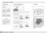
3. Installation Process
3-1. Embedding the Tubing and Wiring
Do not connect tubes to locations that are embedded.
Be sure to bind refrigerant tubing and inter-unit cables
together with vinyl tape.
The power cable must be obtained on-site.
(#12: Less than 85 ft.)
# ... AWG (American Wire Gauge)
Be sure to apply the provided labels to both ends of
the inter-unit cables to prevent miswiring.
Securely seal the end of embedded tubing with vinyl
tape in order to prevent dirt or moisture entry.
In order to prevent insulation breakdown and ground
faults, do not allow the wire ends to come in contact
with rainwater, or be subject to dew condensation.
Deburring
Before
After
Fig. 8
3-2. Use of the Flaring Method
Many of the conventional split system air conditioners
employ the flaring method to connect refrigerant tubes
which run between indoor and outdoor units. In this
method, the copper tubes are flared at each end and
connected with flare nuts.
3-3. Flaring Procedure with a Flare Tool
(1) Cut the copper tube to the required length with a
tube cutter. It is recommended to cut approx. 12" to
20" (30 to 50 cm) longer than the tubing length you
estimate.
(2) Remove burrs at the end of the copper tube with a
tube reamer or file. This process is important and
should be done carefully to make a good flare.
(Fig. 8)

17
When reaming, hold the tube end downward and be sure that
no copper scraps fall into the tube. (Fig. 9)
(3) Remove the flare nut from the unit and be sure to mount
it on the copper tube.
(4) Make a flare at the end of copper tube with a flare tool.*
(Figs. 10 and 11)
(*Use “RIDGID” or equivalent.)
A good flare should have the following characteristics:
inside surface is glossy and smooth.
edge is smooth.
tapered sides are of uniform length.
3-4. Caution before Connecting Tubes Tightly
a) Be sure to apply a sealing cap or water-proof tape to
prevent dust or water from getting into the tubes before
they are used.
b) Be sure to apply refrigerant lubricant to the matching
surfaces of the flare and union before connecting them
together. This is effective for reducing gas leaks.
(Fig. 12)
c) For proper connection, align the union tube and flare
tube straight with each other, then screw in the flare nut
lightly at first to obtain a smooth match. (Fig. 13)
3-5. Tubing Connections
a) Temporary connection:
Screw in 3 – 5 turns by hand. (Fig.14)
b) To fasten the flare nuts, apply specified torque as:
Table 4
NOTE
NOTE
Reamer
Copper
tubing
Fig. 9
Flare tool
Flare nut
Copper
tubing
Fig. 11
Fig. 10
Apply refrigerant
lubricant here and here
Fig. 12
Flare nut
Union
Fig. 13
0 to 0.0196"
(0 to 0.5 mm)
If the special R410A
flare tool is used:
0.0472" (1.2 mm)
If the previous flare tool
(clutch-type) is used:
Adjust so that the amount of tube
p
rotrusion is as shown in the fi
g
ure.
Apply the provided labels
to the indoor and outdoor
unit tubing connectors to
prevent errors in
connections.
Service valve on
narrow tube side
Service valve on
wide tube side
A
B
C
D
Fig. 14
Tube Dia. Nut Tightening Torque
1/4" (6.35 mm) 21/32" (17 mm) Approx. 120 – 160 lbs·in (140 – 180 kgf·cm)
3/8" (9.52 mm) 7/8" (22 mm) Approx. 300 – 360 lbs·in (340 – 420 kgf·cm)
1/2" (12.70 mm) 1-1/32" (26 mm) Approx. 430 – 480 lbs·in (490 – 550 kgf·cm)
5/8" (15.88 mm) 1-5/32" (29 mm) Approx. 590 – 710 lbs·in (680 – 820 kgf·cm)

18
3-6. Insulation of Refrigerant Tubing
To prevent heat loss and wet floors due to dripping of con-
densation, both tubes must be well insulated with a
proper insulation material.
The thickness of the insulation should be a minimum 5/16"
(8 mm). (Fig. 16)
For wall-mounted units
After connecting the refrigerant tubing to the outdoor unit
and performing a leak test on the connecting part, insulate it
with the tubing insulation. (Fig 17a)
For ceiling-mounted cassette units
Wind the insulation tape around the flare nuts at the tube
connections. Secondly cover up the tubing connections
with the flare insulation (1/8" (T3, supplied)). Then wind the
other flare insulation (3/16" (T5, supplied)). Finally, fasten
the insulation at both ends with the supplied vinyl ties.
(Fig. 17b)
Insulation material
The material used for insulation must have good insulation
characteristics, be easy to use, be age resistant, and must
not easily absorb moisture.
IMPORTANT
Indoor unit
Outdoor unit
Spanner
Torque wrench
Fig. 15
Insulation
Min.
5/16"
(8 mm)
Thickness:
min. 5/16"
(8 mm)
Fig. 16
Insulation
Fig. 17a
CAUTION
Be sure to match refrigerant
tubing and electric wiring
between indoor and outdoor
units.
Fig. 17b
Fig. 17c
Never grasp the drain or refrigerant connecting out-
lets when moving the unit.
Insulation tape (supplied) Flare insulation (3/16"(T5, supplied) )
Flare insulation (1/8"(T3, supplied) )
Tube insulation
(not supplied)
Vinyl tie (supplied)
Flare nut
The procedure used for installing
the insulation for both wide and
narrow tubes are the same.
Flare
insulation (supplied)
Vinyl tie (supplied)
Insulation tape (supplied)
Refrigerant tubing
and insulation
(not supplied)
Drain pipe and insulation
(not supplied)
Drain hose insulation
and vinyl tie
(supplied)
Drain hose
and hose band
(supplied)

19
4. Air Purging
Air and moisture remaining in the refrigerant system have
undesirable effects as indicated below. Therefore, they
must be purged completely.
pressure in the system rises
operating current rises
cooling efficiency drops
moisture in the air may freeze and block capillary tubing
water may lead to corrosion of parts in the refrigerant
system
Air Purging with a Vacuum Pump
(for Test Run)
In order to protect the earth’s environment, be sure to use
a vacuum pump to perform the air purge.
(Never perform an air purge by using the refrigerant gas
cylinder or other external gas, or by using the gas inside
the outdoor unit.)
Fig. 20
CAUTION
In order to prevent charging errors
with the air conditioner that uses
R410A, the screw diameter at the
service valve charging port has
been changed. When recharging or
performing other servicing, use the
special charging hose and manifold
gauge.
Service
valve on
wide tube
side
Service
valve on
narrow
tube side
A
B
C
D
Vacuum
pump
Vacuum pump
adapter
(for preventing
reverse flow)
(special for
R410A)
High-pressure valve
Manifold gauge
(special for R410A)
Low-pressure
valve
Leave the
valve open.
Open
Charging hose
(special for R410A)
Hex wrench
With push-pin
HiLo
3-7. Taping the Tubes
(1) At this time, the 2 refrigerant tubes (and electrical wire
if local codes permit) should be taped together with
armoring tape. The drain hose may also be included
and taped together as 1 bundle with the tubing.
(2) Wrap the armoring tape from the bottom of the outdoor
unit to the top of the tubing where it enters the wall. As
you wrap the tubing, overlap half of each previous tape
turn. (Fig. 18)
(3) Clamp the tubing bundle to wall, using 1 clamp approx.
every 47" (120 cm).
Do not wind the armoring tape too tightly, since this will
decrease the heat insulation effect. Also, be sure the con-
densation drain hose splits away from the bundle and drips
clear of the unit and the tubing.
3-8. Finishing the Installation
After finishing insulating and taping over the tubing, use
sealing putty to seal off the hole in the wall to prevent rain
and draft from entering. (Fig. 19)
NOTE
Fig. 18
Clamp
Insulated tubes
Apply putty here
Tubing
Fig. 19
CAUTION
After a tube has been insulated,
never try to bend it into a narrow
curve, as this may cause the tube
to break or crack.
/