Diamond Engineering 6000 User manual
- Category
- Water pumps
- Type
- User manual
This manual is also suitable for

1
Desktop Antenna Measurement System
Model 6000

2
This Publication, including all photographs, illustrations and software is protected under international
copyright laws, with all rights reserved . Neither this manual, nor any of the material contained herein,
may be reproduced without the express written consent of Diamond Engineering. The information in
this document is subject to change without notice. Diamond Engineering makes no representations or
warranties of merchantability or fitness for any particular purpose. Further Diamond Engineering
reserves the right to revise this publication and to make changes from time to time in the content
hereof without obligation of Diamond Engineering to notify any person of such version changes.
Trademarks
IBM, VGA and PS/2 are registered trademarks of International Business Machines.
AMD is a registered trademark of Advanced Micro Devices Inc.
Intel, Pentium III/4 Are registered trademarks of Intel Corporation
Microsoft, and Windows NT/95/98/ME/2000/XP are registered trademarks of Microsoft Corporation.
VEE, VEE Runtime, and Agilent are registered trademarks of Agilent Corporation.
HP, HPIB, are registered trademarks of the Hewlett Packard Company.
Anritsu, Scorption are registered trademarks of the Anritsu Corporation.
Labview is a registered trademark of the National Instruments Corporation
Matlab is a registered trademark of Mathworks.
NOTICE

3
Table Of Contents
NOTICE .........................................................................................................................2
Introduction ............................................................................................................................................................ 6
System Overview................................................................................................................................ 7
Key Features .......................................................................................................................................................... 7
Minimum System Requirements ....................................................................................................... 8
USB Port Platform Controller Unit .................................................................................................... 9
Parallel Port Platform Controller Unit.............................................................................................. 10
Chapter 1 - Installation and Configuration ..................................................................................... 12
Tripod and Elevation Unit Assembly .................................................................................................................. 13
Attaching the optional thrust plate-.................................................................................................................... 14
Attaching the cables............................................................................................................................................ 15
Installing the Software ........................................................................................................................................ 16
Connecting the Controller and Installing the drivers. (Blue USB models Only) ............................................. 16
Installing the Parallel Port drivers (Pre-2005 Parallel interface units ONLY).................................................. 17
Installing the Userport.Sys Driver (Required for Windows NT, 2000, And XP Professional users) ................ 17
VEE Runtime I/O Configuration .......................................................................................................................... 18
Calibrating/Setting the Vertical Movement to 0 Degrees -- See Also Vertical Calibration Settings ............ 20
Platform Positioning Test. ................................................................................................................................... 20
Special Installation Notes ................................................................................................................................... 21
Measurement Settings......................................................................................................................................... 24
Instrument Selection and Settings ..................................................................................................................... 24
Chapter 2 - Software Overview........................................................................................................ 24
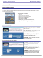
Measurement Settings......................................................................................................................................... 25
Receive Instrument -Spctrum Analyzer Settings .............................................................................................. 25
Measurement Settings......................................................................................................................................... 26
Calibration Settings............................................................................................................................................ 27
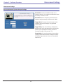
Measurement Controls ........................................................................................................................................ 28
Post Measurement Options ................................................................................................................................. 28
Meaurement Status and Displays...................................................................................................................... 29
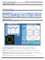
Data Processing Introduction.............................................................................................................................. 30
Data Registers ...................................................................................................................................................... 31
Visualization Options .......................................................................................................................................... 32
Measurement Calculator..................................................................................................................................... 34
Dipole Link Simulator ......................................................................................................................................... 34
Vertical Swing Correction ................................................................................................................................... 34
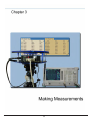
Chapter 3 - Making Measurements .................................................................................................35
Performing a Scalar Calibration ........................................................................................................................ 36
Making a basic Horizontal/Azimuth Measurement ........................................................................................... 37
Making a basic Vertical/Elevation Measurement .............................................................................................. 37
Performing an AZ/EL Scan Measurement ......................................................................................................... 38
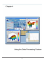
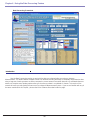
Chapter 4 - Using the Data Processing Feature ............................................................................ 40
Data Processing Screenshot ............................................................................................................................... 40
Saving and Loading Measurement Data Sets................................................................................................... 41
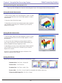
Viewing and working with measurements in 3D ............................................................................................. 42
Viewing and working with the Dynamic Amplitude Plot ................................................................................. 43
Using the Measurement Calculator / Register Math Function. ........................................................................ 45
Exporting Data ..................................................................................................................................................... 47
Using the Dipole and Isotropic Link Calculator-................................................................................................ 49
Group Delay Function ......................................................................................................................................... 51
Chapter 5 - Troubleshooting and Service...................................................................................... 54
Troubleshooting ................................................................................................................................................... 54
Warranty Information .......................................................................................................................................... 55
Replacement Parts .............................................................................................................................................. 55
Contact Information ............................................................................................................................................. 55

4

5

6
Introduction
Congratulations on your purchase of a Diamond Engineering
Desktop Antenna Measurement System! Also Known As DAMS
Diamond Engineering’s Desktop Antenna Measurement System has been designed to aid in
the testing and development of small to medium sized Antennas. Using state of the art software this
system enables you to make many different types of measurements with complete user-definable
configuration settings. The advanced Processing Feature enables you to not only plot 3D graphs of
the measurements, but save and recall those measurements for future use or comparison. Using the
Group Delay function will enable you to calculate the exact distance of the Test Antenna, Identify
Multipath rays, and eliminate the need to use another measuring device. Our software also allows you
to export your data to a 3rd party application or spreadsheet.
This manual will fully assist you step by step with Assembling, configuring, and using the
Desktop Antenna System. To achieve the full functionality of the rotator system we expect you to have
some prior knowledge about the concepts and theories about Microwaves and Antenna Design and
Development before using this software and rotator unit.
We cannot emphasize enough about the importance of fully reading and understanding this
manual before using this piece of equipment to avoid any risk of damaging the unit and possibly
voiding your warranty.
Best Regards, The Diamond Engineering Team

7
Key Features
· Light Weight- Platform is made of high quality, light weight Acrylic material for easy portability
·
USB Port Connectivity- Unit easily connects to the computer using a standard USB cable.
·
User Friendly Software- Our software has been designed to be understood easily to ensure the
shortest time to successful Antenna Measurement.
·
Quality Components- The rotator unit is built only with the best of components for long lasting
reliability.
·
Compatibility- Our Software supports a wide range of network analyzers and instruments that
use the GPIB / 488.1/2 and SCPI methods of communication.
·
Phase/Angle Measurement-Software can measure All four Vector S-Parameters over a
specified frequency range at each measurement point.
·
2-axis movement- 360 Degrees Horizontal at 1/4 degrees per measurement to +/- 45 degrees
vertical movement angle at 1 degree per step.
·
DC to 18 Ghz. Measurement Range- A wide frequency use range allows for a more diversified
range of antennas that can be tested with the system.
·
Rotary SMA Joint- Using a custom developed “Near Zero” noise Rotary Joint the system can
make accurate measurements without jeopardizing signal integrity.
·
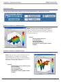
Data Processing Feature-Designed for post measurement processing you can perform a range of
functions such as:
o Complete 3D Visualization for All Frequencies and Angles
o 3D Azimuth/Elevation plots for true 3D data representation.
o Ability to save and Recall Data Sets from RAM or local Disk
o Group Delay (distance calculation)
o Spherical 3D plots
o Ability to work with 4 different data sets at once
o Ability to map over 50,000 Different measurement Points onto one 3D chart
o Real-time Data over Movement V.S. Frequency
o Dipole Link Calculator
o Calculator for modifying measurement results and comparing antennas
o Export your data to a Spreadsheet or 3rd part application such as MatLAB
o Dipole Link Simulator allows creation of simulated dipole antennas
Features
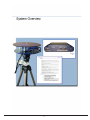
System Overview

8
• AMD/Pentium Class Computer with 1000 Mhz. Processor Or Higher (2 Ghz or Higher Recommended)
• 512 MB Ram
• 500 Megabytes Hard Disk Space
• 1 Available USB Port
• 1024x768 Display Resolution (Minimum)
• Windows 95/98/ME/NT/2000/XP Operating Systems are supported
*Windows XP home is not compatible with the Parallel Port Model
• Keyboard and Mouse
• Compatible Network Analyzer or Power Meter/Spectrum Analyzer and Signal Generator.
As of the date of this maual the following Insturments are are currently supported by the Standard
DAMs Software.
VECTOR NETWORK ANALYZERS
-HP/Agilent 8510 Series
-HP/Agilent 8714 Series
-HP/Agilent 8720 Series
-HP/Agilent 8753 Series
-HP/Agilent 5071 Series
-Wiltron/Anritsu 46xx Series Analyzers (Scorpion)
-Rhode & Schwarz ZVx Series
SIGNAL GENERATORS
-HP 83650 Series
-HP 8350 Series
POWER METERS
-Elva DPM-10
-HP436A
-HP437B
-ML2438A (antritsu)
SPECTRUM ANALYERS
-HP8565 Series
• Printer (optional) for printing Measured Antenna Plots
To Find System Information:
- Right Click on “my computer” on your
windows desktop and select Properties
Minimum System Requirements
System Overview Requirements

9
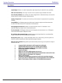
USB Port Platform Controller Unit
System Overview
Platform Controller top view
Platform Controller rear view
The USB Platform Control unit is a highly accurate Microprocessor based stepper controller. Movement signals are
sent from the measurment PC to the controller unit where precision stepping sequences are generated. We also offer a
development kit enabling you to write your own software to control the platform.

10
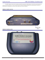
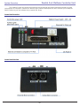
Control Unit Side View
Control Unit Front View
Parallel Port Platform Controller Unit
The Platform Control unit controls the positioning of the Horizontal and Vertical movements based on signals
recieved from the Computer’s Parallel Port. We also offer a Platfrom development kit which will allow you to adapt the
DAMS Platform to your own software using a special DLL library.
System Overview

11

12
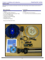
Upon receiving your shipment of the Rotator Unit Please inspect the package to ensure all pieces are there and not
damaged
Main components
1. Positioner Platform
2. Tripod
3. Users Manual with Software CD
4. 2- 10’ Calibrated SMA measurement Cables
5. 20’ (6.2m) Parallel Cable
6. 12v AC to DC wall adapter
7. Elevation Movement Assembly
8. Hex Wrench Tool.
9. Elevation Mount Spacer
-Copy of your Order (Not Shown)
Accessories
10. Digital Level/Elevation Calibration Tool -
(optional)
11. Laser Alignment Tool (Optional)
12. Acrylic Thrust Plate (assembled with platform)
Unpacking the System
Chapter 1 - Installation and Configuration
Package Contents

13
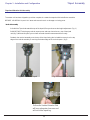
Tripod and Elevation Unit Assembly
The rotator unit has been shipped to you either complete in a matter that requires Minimal effort to assemble.
BEFORE YOU BEGIN: Unpack ALL items and ensure there is no damage or missing parts.
-Vertical Assembly
1. Unfold the Tripod and extend the top of the tripod 1/2 way and secure the height adjustment- (Fig. 1)
2. IMPORTANT! Take the grey vertical mount spacer and snap it onto the very top of the tripod
neck(fig. 2) Without this piece your unit will not make elevation measurements accuratly.
3. atttach the vertical assembly onto the top of the tripod using the included hex wrench so the top
edge of the vertical assembly is touching the bottom edge of the vertical spacer. (fig 3)
Fig 1- Extend the Tripod Fig 2- Attach vertical Spacer
Fig 3- Attach vertical Assembly-
Ensure the Vertical Actuator Rod
will have adequate clearance and
will not hit the tripod leg.
Chapter 1 - Installation and Configuration Tripod Assembly

14
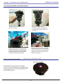
Connecting the platform and vertical actuator.
Attach the Thrust Plate using the 4 includeded
10-32x1/4” Screws. be sure not to overtighten screws
and if using your own screws be sure they do not hit
the metal bearing below.
1. Ensure that the Azimuth of the
tripod is unlocked.
2.Place the Tripod head in a
horizontal position and tighten the
locking screw (Loosen screw after
assembly)
3. Align the colored piece of tape on the
platform with the tape on the tripod head
and insert the platform into the head at a
30 degree angle, the head will automati-
cally lock the platform into position.
4. Loosen the Tilt Lock (Pic 2) enough
to allow the platform to tilt and connect
the vertical actuator rod to the platform ,
tighten the locknut to ensure the rod
does not disconnect.
Applies to Acrylic and Aluminum models.
Chapter 1 - Installation and Configuration Platform Assembly
Attaching the optional thrust plate-

15
Attaching the cables
You should have received 5 Seperate Cables and a power supply with your DAMS System.
1. 2- 10 Ft. Custom Calibrated SMA cable.(1-20’ Cable Optional)
2. 1- USB cable.
3. 2- 6m Platform control cables
Step 1. connect the USB cable to the Platform Controller. DO NOT CONNECT TO PC YET.
Step 2. connect the Power Supply wire to the Platform Controller.
Step 3. connect one end of the Calibrated SMA cable to the bottom of the platform.
Step 4. Attach other end of SMA cable to your Analyzer. **USE CARE** cable damage can compromise antenna
results.
Step 5. Connect the straight end of the yellow cable with the black band on the connector to the
“Horizontal” port on the Platform Controller and the non-banded cable to the “vertical” port.
Step 6. Connect the other ends the yellow cables to the platform. the banded right-angle connector connects to the
turntable. and the non-banded connector goes to the vertical actuator.
Chapter 1 - Installation and Configuration Cable Connections

16
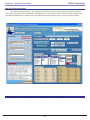
1. Place Software CD in CD-ROM drive, The CD Menu should Start Automatically, If the menu does
not start automatically run setup.exe from your CD-ROM in “My Computer” or from Windows Explorer
2.Click next/ok through all Following Screens.
3. Before the software is finished installing , the Agilent Runtime setup will start, Continue through this
setup as you would a normal software installation.
4. After installation is complete the Software can be found on your desktop and in the start menu
under“DAMS”
Note To NT/200/XP Pro. Users! If you using a Parallel Port Controller— You must install the UserPort
driver discussed on the next page.
Installing the Software
Chapter 1 - Installation and Configuration Software and Hardware Installation
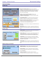
Connecting the Controller and Installing the drivers. (Blue USB models Only)
1. Connect the DAMS Platform Controller to the Computer using the included USB Cable. A window
should appear indicating that a new device has been found. Do not select the option to automatically
search for the latest driver!.
2. Click the Box labled Search Manually then click “Next”
3. Select CD-ROM
4, Click Next, You will then be prompted that the driver has not passed the WHQL certification. select the
“Continue Anyways” button.
5. Click Finish.
6. A new window will pop up indicating another device has been found, repeat steps 2-5 above.
7. You have now installed the DAMS Platform Controller and must continue with the Instrument Configu
ration.

17
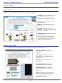
Installing the Userport.Sys Driver (Required for Windows NT, 2000, And XP Professional users)
NOTE: If you recieved a Pre-Configured Laptop From us, the Steps below have already been performed
-you will ony need to follow the steps below if you are Re-Installing the Operating System.
Overview
This guide will Assist you with the Required Changes that must me made to windows XP Professional before the soft-
ware and platform will function correctly
Note about Windows XP: The Antenna Measurement Software Has only been tested and is only supported on the
Professional version of Microsoft Windows XP .
(LPT) Parallel Port Driver Installation Instructions:
Step 1:
The software installation has placed a Folder named “UserPort” located in the “C:\DAMS” Folder.
The userport.sys file allows the Windows XP operating system to communicate with the parallel port and control the
platform. Follow the instructions bellow to install the Userport.sys Driver.
-- For additional Information Please read the
Userport.PDF located in the Userport Folder ---
Step 2:
Setting the Compatibility mode for VEE Runtime 6.0 (XP PRO ONLY!)
In order for the software to work absolutly correctly we reccomend setting
the Windows XP compatibility mode to Windows 98/Me Mode for less
chances of errors caused by the windows XP Kernel.
1. Open “My Computer” located in the Start Menu
2. Open your “C:” Drive
3. Double click on the “Program Files” Folder
4. Double Click “Agilent” then double click the “Vee Pro Runtime”
Folder.
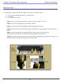
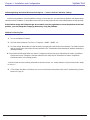
1. Go to the “C:\dams\userport\” folder and copy the
“Userport.sys” file to the windows
system32\Drivers Folder. it is usually located in
“C:\windows\system32\drivers”
2. Run the Userport.Exe program as shown at right
and Select the I/O range you wish to use and
Press Start. (if you do not know which ports to leave
open just press start and the defaults will be used)
Chapter 1 - Installation and Configuration Software Configuration
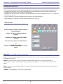
Connecting the controller and installing the Parallel Port drivers (Pre-2005 Parallel interface units ONLY)

18
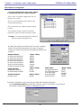
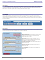
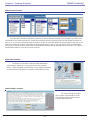
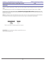
5. Press the “Advanced” button to bring up the Advanced Properties Dialog Box.
Set the Instrument Timeout to 15 seconds. Press OK , then OK, then “SAVE”. You have now
successfully completed the Analyzer Configuration Process.
4.
Select your analyzer from the list and Click on the “Properties
button” You should see the window to the right, Change the
name that is shown to one from the list below that matches your
analyzer.
Network Analyzer
HP 8510 series Analyzers
HP 8714 series Analyzers
HP 8720 series Analyzers
HP 8753 series Analyzers
HP 5071 series Analyzers
Anritsu Scorpion Analyzers
Rhode & Schwarz RS series
You must complete these steps for the Sofware
to communicate with your network analyzer!.
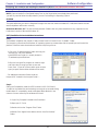
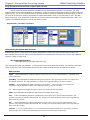
1. Click Start -> Programs->Agilent VEE pro 6.0
Runtime-> I/O Config
2. Turn on you Network Analyzer and Click the
“Find Instruments button.
3. You should see your network analyzer appear
in the list
The instrument number consists of the GPIB
controller ID number and the Instrument number
Example: ID (newinstrument@1416) 14=Nat inst
GPIB controller 16=Analyzer ID #
“Name” setting
HP8510
HP8714
HP8720
HP8753
HP5071
Scorpion
RSZVR
VEE Runtime I/O Configuration
Chapter 1 - Installation and Configuration Software Configuration
“Name” setting
HP836
HP8350
Signal Generator
HP 83650B Signal Gen.
HP 8350 Sweep Generator
“Name” setting
HP436
HP437
ML2438
ML4803
DPM10
Power Meter
HP 436A Power Meter
HP 437B Power Meter
Anritsu ML2438A
Anritsu ML4803A
ELVA-1 DPM 10
Spectrum Analyzer
HP 8565 Series
“Name” setting
HP8565

19
Tripod Compatibility Information
The DAMS system has been designed so that it will operate with most any tripod, when purchasing a new tripod
you must ensure that all of the parts from the current system will fit onto the new trupod without angle or clearance
problems. Once you are ready to configure the software please read the “DAMS Application note / Tips and Tricks” for a
complete description and howto calibrate the vertical movement with a
Tripod other than the one that was included with
your Antenna Measurement System. If you need Assistance you are welcome to call or e-mail us and we will be glad to
help.

20
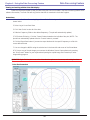
Calibrating/Setting the Vertical Movement to 0 Degrees -- See Also Vertical Calibration Settings
In order for the software to move the platform correctly on the vertical axis you must have the platform at 0 degrees when
starting the DAMS Softtware - or the platform must match the vertical position shown in the software before moving vertically.
If the Platform Angle and Software Angle do not match, Use the Jog buttons to move the platform to the level
position, you can change the Change jog distance by using the pulldown.
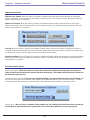
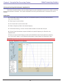
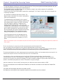
Platform Positioning Test.
1. Turn on the Platform Controller
2. Start the rotator software, Click Start -> Programs -> DAMS ->DAMS x.xx
3. Click the orange “Manual Move” button located in the upper left hand section of the software. The platform should
now horzontally move the number of times specified in the “Total Number of Measurements” window completing a
360 degree sweep.
4. Set the Vertical Differential slider to a value of -5 degrees and press the green “Manual Move” button, the platform
should now move to -5 degrees. Slide the slider back to 0 and press the “Manual Move” button. the platform
should now return to it’s starting position.
****If the Rotator Unit successfully performed the above functions, the rotator platform is fully functional and is ready
for Use.****
6. If The Rotator Unit does not Perform one or more of the above tests please refer to the Troubleshooting Section
located on Page 43
Chapter 1 - Installation and Configuration System Test
Page is loading ...
Page is loading ...
Page is loading ...
Page is loading ...
Page is loading ...
Page is loading ...
Page is loading ...
Page is loading ...
Page is loading ...
Page is loading ...
Page is loading ...
Page is loading ...
Page is loading ...
Page is loading ...
Page is loading ...
Page is loading ...
Page is loading ...
Page is loading ...
Page is loading ...
Page is loading ...
Page is loading ...
Page is loading ...
Page is loading ...
Page is loading ...
Page is loading ...
Page is loading ...
Page is loading ...
Page is loading ...
Page is loading ...
Page is loading ...
Page is loading ...
Page is loading ...
Page is loading ...
Page is loading ...
Page is loading ...
-
 1
1
-
 2
2
-
 3
3
-
 4
4
-
 5
5
-
 6
6
-
 7
7
-
 8
8
-
 9
9
-
 10
10
-
 11
11
-
 12
12
-
 13
13
-
 14
14
-
 15
15
-
 16
16
-
 17
17
-
 18
18
-
 19
19
-
 20
20
-
 21
21
-
 22
22
-
 23
23
-
 24
24
-
 25
25
-
 26
26
-
 27
27
-
 28
28
-
 29
29
-
 30
30
-
 31
31
-
 32
32
-
 33
33
-
 34
34
-
 35
35
-
 36
36
-
 37
37
-
 38
38
-
 39
39
-
 40
40
-
 41
41
-
 42
42
-
 43
43
-
 44
44
-
 45
45
-
 46
46
-
 47
47
-
 48
48
-
 49
49
-
 50
50
-
 51
51
-
 52
52
-
 53
53
-
 54
54
-
 55
55


Diamond Engineering 6000 User manual
- Category
- Water pumps
- Type
- User manual
- This manual is also suitable for
Ask a question and I''ll find the answer in the document
Finding information in a document is now easier with AI
Other documents
-
Anritsu 37xxxE User manual
-
 China Electronics Technology Instruments AV3672 Series User manual
-
Agilent Technologies Agilent 86120C User manual
-
-
BakkerElkhuizen BNEQNOTE350 Datasheet
-
Quick Dam QDGGFB-20 User manual
-
-
-
Keysight VEE Pro 9.33 Quick start guide
-
Supersonic SC-603 User manual
