Page is loading ...

Cygnus 3 Data Logger
Operating & Accessories Manual
Doc No. M4-CYG3-M-ENG_Iss2.doc
16 April 2013
(Mk4 Cygnus 3 Gauges)

Cygnus 3 Operating Manual
M4-CYG3-M-ENG_Iss2.doc
2
QUALITY POLICY STATEMENT
“Cygnus Instruments is committed to being a premier supplier of
niche test and measurement instruments. Cygnus is dedicated
to customer satisfaction. Cygnus will always provide products
and service of exceptionally high quality. We will listen to our
customers and be both market-led and technology driven. And
by utilising a formal Operations Management System that
complies with industry standards, we will continually improve
what we do and how we do it.”
Cygnus is an ISO-9001 accredited company.
The scope of our accreditation covers all our products and
services.

M4-CYG3-M-ENG_Iss2.doc
Cygnus 3 Operating Manual
3
Contents
1. Introduction ...................................................................... 7
Cygnus 3 Thickness Gauge ...................................................... 7
Multiple Echo Measurements .................................................... 8
Triple Echo Verification ......................................................... 8
Cygnus Instruments ............................................................... 9
2. Gauge Kit Contents ......................................................... 10
3. Gauge Preparation .......................................................... 11
Fitting the Batteries .............................................................. 11
Connecting the Probe ............................................................ 12
Fitting the Protective Sleeve .................................................. 13
Fitting the Neck Strap ........................................................ 14
Optional Krusell Belt Attachment ......................................... 14
4. Gauge Operation ............................................................. 15
Gauge Controls .................................................................... 15
Display and Automatic Backlight ............................................. 16
Function Keys ...................................................................... 16
Numeric Keys ...................................................................... 17
Signal LED .......................................................................... 17
Turning the Gauge On ........................................................... 17
Turning the Gauge Off .......................................................... 18
Automatic Power Off .......................................................... 18
Taking a Thickness Measurement ........................................... 19
Echo-Strength Indicators ....................................................... 19
Coupling Strength Indicator ................................................... 20
Battery Life ......................................................................... 21
Battery Life Gauge ............................................................. 22
Low Battery Warning ......................................................... 22
5. Probes & Membranes ...................................................... 23
Probe Selection .................................................................... 23
Changing the Membrane ....................................................... 24
Membrane Temperatures ...................................................... 25
Probe Selection & Specifications ............................................. 25
Probe Frequency Identification ............................................... 25
Automatic Probe Frequency Setting ........................................ 26
6. Gauge Setup ................................................................... 27
Gauge Menu Diagram ........................................................... 27

Cygnus 3 Operating Manual
M4-CYG3-M-ENG_Iss2.doc
4
Measurement Units ............................................................... 28
Resolution Setting ................................................................ 29
Minimum Thickness Alarm Function. ....................................... 30
Deep Coat Function .............................................................. 31
Deep Coat Warning Message ............................................... 33
Valid Thickness ‘Beep’ Function .............................................. 33
Setting the Time and Date ..................................................... 34
7. Calibration ...................................................................... 37
Calibrating the Gauge ........................................................... 37
Calibration Menu ............................................................... 38
Calibrating to a Known Thickness (Single Point) ..................... 39
Setting the Velocity of Sound ................................................. 40
Displaying the Velocity Menu ............................................... 40
‘Adjust’ Velocity Menu Option .............................................. 41
‘Type In’ Velocity Menu Option ............................................ 42
‘Velocity Table’ Menu Option ............................................... 42
Customising the Velocity Table ......................................... 43
8. Data Logging ................................................................... 45
The Data Logging Process ...................................................... 46
Contents of a Record File ....................................................... 46
Record File Names ................................................................ 47
User Entered File Names .................................................... 47
Auto File Name ................................................................. 47
GaugeID Number ............................................................ 48
Data Logger Menu ................................................................ 49
Quick Log Record Files .......................................................... 50
Creating a Quick Log Record File ......................................... 50
Grid Point Record Files .......................................................... 52
Creating a Grid Point Record File ......................................... 54
Template Record Files ........................................................... 57
Creating a Record File from a Template ................................ 57
Data Logging Functions and Management ................................ 61
Stopping, Suspending and Resuming Data Logging ................ 61
Logging an Obstruction or No-Reading Point .......................... 62
Moving Position in the current Record File ............................. 63
Adding Additional Measurement Points ................................. 64
How to add Additional Radial Points ................................... 65
Adding a Comment while Data Logging ................................. 66
Displaying the Current Record File Details ............................. 67
Reviewing Template File User Fields ..................................... 67

M4-CYG3-M-ENG_Iss2.doc
Cygnus 3 Operating Manual
5
Opening a Record File ........................................................ 68
Protecting Record Files ....................................................... 69
Deleting Record Files ......................................................... 69
Deleting all Record Files ..................................................... 70
Changing the Velocity or Calibration while Data Logging ......... 71
Auto-Log Function ............................................................. 71
Using the Auto Log Feature .............................................. 72
9. Cygnus 3 Data Logger Manager ....................................... 73
Overview ............................................................................ 73
Installation .......................................................................... 73
Connecting the Data Logger to the Computer ........................... 74
Setting Options ................................................................. 76
Transferring Record Files from the Data Logger ........................ 76
Creating and Printing a Report ............................................... 78
Deleting a Record File ........................................................... 81
Template Files ..................................................................... 81
User Fields ....................................................................... 82
User Field ‘List’ Type ....................................................... 83
Measurement Points .......................................................... 83
Creating a Template File ..................................................... 83
Template Form ............................................................... 85
Transferring Template Files to the Data Logger ...................... 90
10. Microsoft Excel Add-In ................................................. 92
Overview ............................................................................ 92
Installing the Add-In ............................................................. 92
Microsoft Office Excel 2000, XP, 2003 .................................. 92
Microsoft Excel 2007 .......................................................... 93
Creating an Excel Report ....................................................... 95
Additional Measurements .................................................... 97
11. Data Logging Template Tutorial ................................... 99
Create the Excel® Spreadsheet ............................................... 99
Create the Data Logger Template ......................................... 101
Transferring the Template to the Cygnus 3 Gauge .................. 105
Carry out the Survey with the Cygnus 3 ................................ 107
Transfer the Completed Survey Record to Computer ............... 107
Creating the Excel Report .................................................... 108
12. General Points On Thickness Gauging ........................ 111
13. Troubleshooting ......................................................... 112
The Gauge will not Switch On .............................................. 112

Cygnus 3 Operating Manual
M4-CYG3-M-ENG_Iss2.doc
6
Difficulty obtaining a Reading ............................................... 112
If Readings are Erratic or Unstable ....................................... 112
14. The 4 Point Check ...................................................... 113
15. Care and Servicing ..................................................... 114
Cleaning the Gauge ............................................................ 114
Batteries ........................................................................... 114
Environmental ................................................................... 114
Repairs ............................................................................. 114
Returning the Gauge for Servicing ........................................ 115
16. Information ................................................................ 116
Technical Specifications ....................................................... 116
Table of Sound Velocities .................................................... 118
Reading Conversions ........................................................ 119
17. Accessories List .......................................................... 120
Remote Probes with 1.35m (4’6”) Lead ................................. 120
Marinised Probes with Cable Length to Order ......................... 121
Probe Spares and Membranes .............................................. 121
Cables and Leads ............................................................... 122
Miscellaneous Spares .......................................................... 122
Carry Cases ....................................................................... 122
18. Recycling and Disposal (EC Countries) ....................... 123
19. Index ......................................................................... 124

M4-CYG3-M-ENG_Iss2.doc
Cygnus 3 Operating Manual
7
1. Introduction
Cygnus 3 Thickness Gauge
The Cygnus 3 Multiple-Echo Ultrasonic Thickness Gauge is a
rugged, handheld, battery-powered instrument designed for high-
reliability thickness measurement using the multiple-echo
technique.
The Gauge can be used with a choice of single-crystal Ultrasonic
Probes, depending on the thickness and type of material that is to
be measured.
Measurements can be displayed in Metric (mm) or in Imperial
(inch) units and measurement resolution can be selected for either
0.1 or 0.05 mm, (0.005 inch or 0.002 inch). The Gauge has a large
LCD which can be easily read in sunlight and in low-light situations
using a white LED backlight.
The Gauge has the facility to record thickness measurements to
internal Flash memory, these measurements can be easily
transferred to a computer via a USB connection which then can be
used to generate survey reports.
Crystal-controlled Calibration provides stability and accuracy. The
Gauge can easily be calibrated to a known thickness or to a known
Velocity of Sound. Velocity of Sound is displayed in either m/s or
in/μs, depending on the current selection for Measurement Units.
The Gauge is able to operate accurately in a wide range of ambient
temperatures and is environmentally sealed to IP65 for use in wet
or dusty conditions.
The Gauge is a solid-state electronic instrument which, under
normal operating conditions, will give many years of active
service.
Although designed for ease of operation the first time user
should carefully read this manual to familiarise themselves
with the features of the Gauge.

Cygnus 3 Operating Manual
M4-CYG3-M-ENG_Iss2.doc
8
Multiple Echo Measurements
The Gauge works on the pulse-echo principle. The Probe transmits
a very short pulse of ultrasound which enters the test piece. The
Probe then acts as a receiver listening for return echoes,
converting them into electrical signals which are processed to
produce timing information that can be used to determine the
material thickness.
The multiple-echo beam travel is depicted above, spread out in
time, to illustrate the timing method. In reality the beam path is
straight and perpendicular to the surface as the ultrasonic energy
reverberates up and down within the metal (shown on the left).
Each time an echo is reflected back down, a small portion of the
energy comes up through the coatings and is detected by the
Probe which acts as a receiver (e1, e2 and e3).
The delay between echoes at the Probe-face (t2 and t3) is exactly
equal to the time taken to pass through the metal twice, therefore
coatings such as paint are ignored and the measurement displayed
is the metal thickness only.
Triple Echo Verification
The Gauge requires 3 equi-spaced return echoes in order to
calculate a thickness measurement value (t2=t3). This method
ensures the Gauge only displays valid thickness values, the three
echoes provide a reliable method of signal verification. This
process is referred to as Triple Echo Verification.
e1
e2
e3
t2
t3
Valid Thickness Measurement only when : t2=t3
Time
Paint, Dirt etc.
Metal
0
t1
Probe

M4-CYG3-M-ENG_Iss2.doc
Cygnus 3 Operating Manual
9
Cygnus Instruments
Cygnus Instruments Limited, founded in 1983, was the pioneer in
the development of the Digital Ultrasonic Multiple-Echo Technique
used for measurement through coatings. This has long been the
industry standard to ensure that accurate measurements are
taken without the need to zero the Gauge or remove any coatings.
Our philosophy is to work closely with our customers to provide
high quality products, engineered to serve heavy industry & harsh
environments. Cygnus Ultrasonic thickness gauges are designed to
be reliable and simple to use. We have an unrivalled reputation in
over 45 countries around the world.
CYGNUS Instruments Ltd.
Cygnus House, 30 Prince of Wales Road,
Dorchester, Dorset DT1 1PW England.
Tel: +44 (0) 1305 265533 Fax: +44 (0) 1305 269960
www.cygnus-instruments.com sales@cygnus-instruments.com
CYGNUS Instruments Inc. CYGNUS Singapore (S) Pte. Ltd.
1993 Moreland Parkway, Suite 202.
Annapolis, Maryland 21401, USA.
63 Jalan Pemimpin #05-01,
Pemimpin Industrial Building.
577219 Singapore.
Tel: +1 410 267 9771 Tel : +65 6252 5909
Fax: +1 410 268 2013 Fax : +65 6251 1318
www.cygnusinstruments.com www.cygnus-instruments.sg
sales@cygnusinstruments.com sales@cygnus-instruments.sg

Cygnus 3 Operating Manual
M4-CYG3-M-ENG_Iss2.doc
10
3
4
2
5
7
6
8
9
1
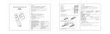
2. Gauge Kit Contents
1. Cygnus 3 Data Logger Gauge
2. Protective Silicone Sleeve
3. Cygnus 3 Operation Manual
4. Blue High-Flex Probe Cable, 1.5 m (4½ ft) *
5. Accessory Pouch, containing Couplant Gel, Spare Membranes,
Membrane Couplant, Membrane Locking Ring Key, 15 mm (or
1/2 inch) Test block and 3 x AA Procell Batteries
6. Adjustable Neck Strap *
7. Probe(s)
8. USB Cable
9. CD – Cygnus 3 Data Logger Manager
* The adjustable neck strap and probe cable will be stored in
either the inside or outside pockets.

M4-CYG3-M-ENG_Iss2.doc
Cygnus 3 Operating Manual
11
3. Gauge Preparation
The Gauge is supplied ready to use out of the box. Just insert the
batteries, connect the probe to the Gauge, turn on the power and
you are ready to take thickness measurements.
Fitting the Batteries
The Gauge requires 3 x AA/LR6/UM3 Batteries. Cygnus supplies
and recommends Duracell Procell Alkaline batteries.
The batteries are located behind a cover at the bottom of the
Gauge. Unscrew this cover to replace the batteries. The batteries
are inserted ‘+’ or ‘pip’ first.
When refitting the battery cover screw ensure it is done up
tightly by hand only. A drop of membrane-oil on the threads
will help to ensure smooth operation and a good seal.
The Gauge is protected against damage from incorrect battery
insertion.
The Gauge can be fitted with NiCad or NiMH rechargeable
batteries but this may reduce the specified operating time.
+
3 x AA
Battery
Cover
Screw

Cygnus 3 Operating Manual
M4-CYG3-M-ENG_Iss2.doc
12
Connecting the Probe
The Probe is connected to the Gauge with the supplied Probe Cable
as shown below. The Lemo 1 connector is removed by pulling back
on its body, not the cable.
Lemo 1
Probe
BNC Connector

M4-CYG3-M-ENG_Iss2.doc
Cygnus 3 Operating Manual
13
Fitting the Protective Sleeve
The Gauge is supplied with a protective Silicone Sleeve that fits
over the Gauge. This sleeve is designed to protect the Gauge
against bumps, scratches and dirt while in use whilst still allowing
Gauge operation and battery replacement.
To insert the Gauge simply push the Gauge down into the sleeve,
a lip at the top of the sleeve will retain the Gauge once fully
inserted.
The Gauge is removed by pushing it out from the bottom.
The sleeve also allows the Gauge to be worn on a belt or
suspended from the Neck Strap included in the kit.

Cygnus 3 Operating Manual
M4-CYG3-M-ENG_Iss2.doc
14
Fitting the Neck Strap
The Gauge is supplied with an adjustable Neck Strap. The ends of
the neck strap clip onto rings at the top of the protective silicone
sleeve.
Optional Krusell Belt Attachment
For attaching the silicone sleeve to a belt or harness we offer an
optional Krusell® belt clip. The belt clip is attached to the
protective silicone sleeve as shown below. This enables the Gauge
to be easily taken on and off the belt clip.
Krusell® Belt
Clip
Attachment
Point
Neck
Strap

M4-CYG3-M-ENG_Iss2.doc
Cygnus 3 Operating Manual
15
Battery
Cover
LCD
Display
Light Sensor
Power
ON/OFF
Key
Probe
Cable
Connection
3 Function
Keys
Signal LED
Alphanumeric
Keys
USB
Connection
4. Gauge Operation
Gauge Controls

Cygnus 3 Operating Manual
M4-CYG3-M-ENG_Iss2.doc
16
Display and Automatic Backlight
The Gauge uses a monochrome graphic LCD with 128 x 64 pixel
resolution. The LCD can be viewed in bright sunlight, and in low
light conditions a white-LED backlight is provided.
The LCD backlight is turned on automatically when the light level
drops below a pre-set level. The backlight will be also be turned off
after the gauge has been idle for 20 seconds (idle means no keys
pressed and no echoes detected).
Function Keys
The Gauge has three keys under the LCD screen with an upward
pointing triangle. The function of each key corresponds to the
word or symbol above it on the screen.
In the measuring screen the three keys are used for:
MENU HOLD* OFF
Pressing this key
displays the gauge
Menu.
Pressing this key
holds the displayed
thickness
measurement on the
screen.
Pressing this key
turns off the gauge
if the key is then
held for 1 second.
When in the menu and other screens the function of these three
keys change. The word or symbol displayed above the key on the
screen denotes the key’s function.

M4-CYG3-M-ENG_Iss2.doc
Cygnus 3 Operating Manual
17
*When data-logging the middle key changes to the LOG function.
Numeric Keys
The Gauge has ten keys for alphanumeric data entry. Text and
numbers are entered by repeatedly pressing the key with the
required character, similar to entering text on a mobile phone
keypad.
The 1 key also provides these characters; + - . *
Example
To input the letter ‘S’ you would press the 7 key four times.
Signal LED
The Gauge has a red/green signal LED that illuminates when data-
logging.
Turning the Gauge On
1.
Press the Power key (red Triangle key)

Cygnus 3 Operating Manual
M4-CYG3-M-ENG_Iss2.doc
18
2.
The Cygnus Instruments logo is briefly
displayed
3.
The software and hardware version
information is briefly displayed
4.
The measurement screen is then
displayed
5.
The Gauge is ready to use
Turning the Gauge Off
1.
Press & Hold the Power button for 1
second
2.
The display shows ‘POWER OFF’ then
the Gauge turns off
Automatic Power Off
The Gauge will turn off automatically 5 minutes after the last
thickness measurement was taken.

M4-CYG3-M-ENG_Iss2.doc
Cygnus 3 Operating Manual
19
Taking a Thickness Measurement
1.
Remove all scale, rust, dirt or loose
coatings and brush the test area clean
2.
Apply couplant to the test surface
3.
Place the probe-face on the clean,
lubricated test surface and make firm
contact applying gentle pressure
4.
The Gauge will display a thickness
measurement or an indication of Echo
Strength if no valid measurement has
been found.
Echo-Strength Indicators
Should the Gauge be unable to detect a stable multiple-echo signal
it displays an Echo Strength indication to help the operator locate
a suitable position.
1.
1 Bar Flashing:
No echoes detected

Cygnus 3 Operating Manual
M4-CYG3-M-ENG_Iss2.doc
20
2.
1 steady + 1 Bar Flashing:
Only 1 echo detected
3.
2 steady + 1 Bar Flashing:
Only 2 echoes detected
4.
3 steady + 1 Bar Flashing:
3 echoes detected but they are not
related
To help obtain a multiple echo reading the operator should
continue to move the probe around to locate a suitable reflector,
using a slight rocking motion.
Coupling Strength Indicator
When the Gauge displays a valid thickness measurement there is a
vertical coupling strength indicator displayed on the left side of the
screen. This shows the strength of the return echo signal giving
the user an idea of
a) How well the probe is coupled to the test material.
b) How attenuative the material and coating is.
/