Tripp Lite SUINT3000RTXL2U Owner's manual
- Type
- Owner's manual

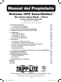
Owner’s Manual
SmartOnline
®
Rack/Tower On-Line UPS System
Model: SUINT3000RTXL2U
(Series Number: AG-0264)
Not suitable for mobile applications.
1111 W. 35th Street, Chicago, IL 60609 USA • www.tripplite.com/support
Copyright © 2019 Tripp Lite. All rights reserved. SmartOnline
®
is a trademark of Tripp Lite.
1. Overview 2
1.1 Package Contents 2
1.2 Optional Accessories 2
2. Important Safety Instructions 2
3. UPS Circuit Block Diagram 3
4. Installation 4
4.1 Mounting (Rack) 4
4.2 Mounting (Tower) 6
4.3 Connection and Start-Up 6
4.4 Optional Connections 7
5. Operation 10
5.1 Front Panel Switches 10
5.2 Advanced Operational Settings 10
5.3 Power Strategy Selection Options 11
5.4 Front Panel Indicator Lights 12
5.5 Rear Panel 13
5.6 Communications 14
5.7 Configuration Options via WEBCARDLX 15
6. Troubleshooting 18
7. Battery Replacement 19
8. Storage and Service 22
8.1 Storage 22
8.2 Service 22
9. Regulatory Compliance 22
Español 23
Français 45
Русский 67
18-09-247-933652.indb 1 2/13/2019 3:27:24 PM

2
2. Important Safety Instructions
1. Overview
SAVE THESE INSTRUCTIONS
This manual contains instructions and warnings that should be followed during the
installation, operation and storage of all Tripp Lite UPS Systems. Failure to heed these
warnings may affect your warranty.
UPS Location Warnings
• Install the UPS indoors, away from excess moisture or heat, conductive contaminants, dust or
direct sunlight.
• For best performance, keep the indoor temperature between 0º C and 40º C.
• Leave adequate space around all sides of the UPS for proper ventilation.
• Do not mount unit with its front or rear panel facing down (at any angle). Mounting in this
manner will seriously inhibit the unit’s internal cooling, eventually causing product damage not
covered under warranty.
The Tripp Lite SmartOnline Rack/Tower System is an on-line, double-conversion UPS offering the
highest level of power protection. Delivering a clean sine wave output and with zero transfer time to
battery in the event of a utility failure, the UPS is suitable for all advanced networking applications.
Each system provides long running battery support with optional extended-run and SNMP/Web
communication ability. Built-in interfaces include USB, RS232 serial and Emergency Power Off
(EPO). The front panel display provides detailed UPS status including battery level and status,
operating mode and load level.
1.1 Package Contents
• UPS
• IEC-320-C19 to C20 Detachable Power Cord (1.5 m)
• 2 x IEC-320-C13 to C14 Detachable Power Cord (1.8 m)
• 4-Post Rail Kit
• Rack-Mount Ear Kit
• USB Cable
• RS232 Cable
• Owner’s Manual
1.2 Optional Accessories
• WEBCARDLX: Internal network interface card for SNMP/Web control and monitoring.
• 2POSTRMKITWM: Supports rack-mount UPS and battery packs in 2-post rackmount or
wall-mount configurations.
• 2-9USTAND: Supports rack-mount UPS and battery packs in an upright tower configuration.
• External battery packs: Support extended runtime. Compatible models include BP72V15-2U
(Limit 1), BP72V18-2US (Multiple) and BP72V28RT-3U (Multiple).
Visit the specification page for your UPS system at www.tripplite.com for detailed extended runtime
data and additional accessory options.
18-09-247-933652.indb 2 2/13/2019 3:27:24 PM

3
2. Important Safety Instructions
3. UPS Circuit Block Diagram
UPS Connection Warnings
• Connect the UPS directly to a properly grounded AC power outlet.
• Do not modify the UPS plug, and do not use an adapter that would eliminate the UPS ground
connection.
• Do not use extension cords to connect the UPS to an AC outlet.
• If the UPS receives power from a motor-powered AC generator, the generator must provide
clean, filtered, computer-grade output.
• The AC outlet must be installed near the UPS system and must be easily accessible for
disconnection.
• Do not plug the UPS into itself; this will damage the UPS.
• To remove AC voltage from the UPS, pull the plug from the socket outlet.
Equipment Connection Warnings
• Use of this equipment in life support applications where failure of this equipment can reasonably
be expected to cause the failure of the life support equipment or to significantly affect its safety
or effectiveness is not recommended.
• Do not connect surge protectors or extension cords to the output of the UPS. This might damage
the UPS and may affect the surge protector and UPS warranties.
• Connect the UPS to an outlet that is adequately protected against excess currents, short circuits
and earth faults, as part of the building installation. The outlet protection for the UPS should be
in series with the mains input.
• To reduce the risk of fire, connect only to a circuit provided with 240V/120V 20A maximum
branch circuit overcurrent protection, installed in accordance with local and national electrical
wiring regulations. The circuit breaker must meet the rated short circuit capacity of at least 1KA.
In Europe, the circuit breaker must meet the IEC/EN 60934 standard and have a contact air gap
of at least 3 mm.
18-09-247-933652.indb 3 2/13/2019 3:27:24 PM

4
4. Installation
1
2
C
C
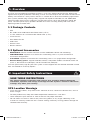
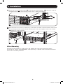
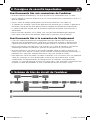
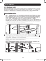
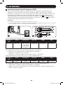
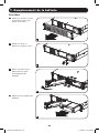
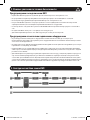
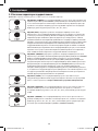
4.1 Mounting (Rack)
Mount your equipment in either a 4-post or 2-post rack or rack enclosure. The user must
determine the fitness of hardware and procedures before mounting. If hardware and procedures are
not suitable for your application, contact the manufacturer of your rack or rack enclosure. The
procedures described in this manual are for common rack and rack enclosure types and may not
be appropriate for all applications.
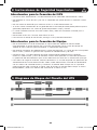
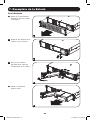
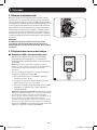
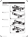
4-Post Mounting
1
The included plastic pegs
A
will temporarily support the empty rackmount shelves
B
while the
permanent mounting hardware is prepared. Insert a peg into the third hole from the top on the
front end of each bracket. On the rear end, insert a peg into the center hole. (Each front
bracket has 6 holes and each rear bracket has 5 holes.) The pegs will snap into place.
After installing the pegs, expand each shelf to match the depth of your rack rails. The pegs will
fit through the square holes in the rack rails to support the shelves. Refer to the rack unit
labels to confirm that the shelves are level in all directions.
Note: The support ledge of each shelf must face inward.
A
A
B
2
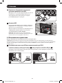
Remove the pegs at the front end of each bracket. Secure the shelves
B
to the mounting rails
permanently using the included screws and cup washers
C
as shown. Place 2 screws at the
front of each rail (4 total) and 2 screws at the back of each rail (4 total). Tighten all screws
before proceeding.
Note: The rear pegs may be left in for installation, but the front ones must be removed before the bracket is
secured by screws.
WARNING!
Do not attempt to install the UPS until the required screws have been inserted and
tightened. The plastic pegs will not support the weight of the UPS.
B
18-09-247-933652.indb 4 2/13/2019 3:27:25 PM

5
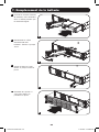
4. Installation
D
G
G
F
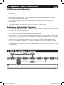
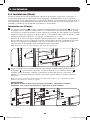
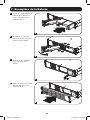
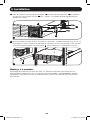
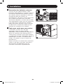
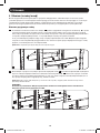
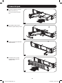
3
4
3
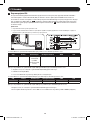
Attach the UPS mounting brackets
D
to the forward mounting holes
E
of the UPS using the
included hardware
F
. The mounting bracket “ears” should face forward.
E
4
With the aid of an assistant (if necessary), lift the UPS and slide it into the shelves. Attach the
UPS mounting brackets to the forward mounting rails with user-supplied screws and washers
G
. Tighten all screws securely.
2-Post Mounting
To mount 2U UPS models in 2-post racks, the addition of a Tripp Lite 2-Post Rack-mount
Installation Kit (model: 2POSTRMKITWM, sold separately) is required. See Installation Kit owner’s
manual for installation procedure.
18-09-247-933652.indb 5 2/13/2019 3:27:26 PM

6
1
2
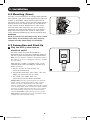
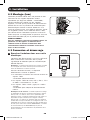
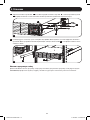
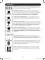
4.2 Mounting (Tower)
The UPS can be mounted in an upright tower position
with optional base stands sold separately by Tripp Lite
(model: 2-9USTAND). When mounting the UPS on
adjustable base stands, make sure the control panel is
toward the top. The control panel may be rotated to
make it easier to read. Remove the 4 front screws
from the front panel and take it off. Pinch the tabs
located on the sides of the LED panel, and rotate it.
Replace the front panel and secure it. Front panel
setup should be performed by service personnel only.
WARNING!
All UPS systems are extremely heavy. Use caution
when lifting and mounting. User must properly
stabilize the UPS when lifting and mounting.
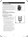
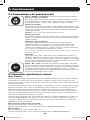
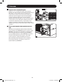
4.3 Connection and Start-Up
1
Plug the UPS system into an
electrical outlet.
The UPS system must be connected to a
dedicated circuit of sufficient amperage. Refer to
the UPS system nameplate for input requirements.
Note: The UPS will pass unfiltered, unregulated power to
the outlets as soon as it is plugged in. Bypass is enabled
from the factory.
After the UPS system is plugged in with a user-
supplied power cord, the following sequence of
events will occur:
1. The fan will turn on and all LEDs will
illuminate momentarily.
2. The percent level LEDs (25%, 50%, 75% and
100%) will illuminate one at a time.
3. The “LINE” and “LOAD” LEDs will
illuminate to indicate normal operation.
Voltage Note: The UPS system supports a nominal AC
voltage setting of 200V, 208V, 220V, 230V or 240V.
230V is the factory default setting. The full output
capacity of 2500 watts is available when the UPS system
is set at 208V, 220V, 230V or 240V. The output capacity
is reduced to 2160 watts when the UPS is set to 200V.
The nominal voltage setting can be changed with the
optional WEBCARDLX internal accessory card. See the
WEBCARDLX documentation for more information about
changing the nominal voltage setting.
4. Installation
1
18-09-247-933652.indb 6 2/13/2019 3:27:27 PM

7
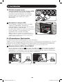
2
Plug equipment into the UPS
system’s AC outlets.
The UPS system is designed to support
computer equipment only. The UPS system will
become overloaded if household appliances or
laser printers are connected to its outlets.
4.4 Optional Connections
The UPS system will function properly without these connections.*
* Note: PowerAlert software (available as a FREE download at www.tripplite.com) or the optional WEBCARDLX
internal accessory card is required to control some of the advanced features of the UPS system, including
economy mode, nominal AC voltage settings and frequency conversion settings. The factory defaults are suitable
for most applications.
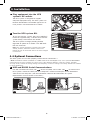
1
USB and RS232 Serial Communications
Use the included USB cable (see
1a
) or RS232 (DB9) serial cable (see
1b
) to connect the
UPS system’s communication port to a computer’s communication port. Install PowerAlert
software on the computer. (See the PowerAlert software documentation for system
requirements and installation instructions.)
4. Installation
2
3
3
Turn the UPS system ON.
To turn on the UPS system, press the “ON/TEST”
button for approximately 1 second until the UPS
system beeps, then release the button.
The UPS system will begin providing filtered,
regulated AC power to its outlets. The “ON LINE”
LED will illuminate.
Note: UPS system will function properly upon initial
startup; however, maximum runtime for the unit’s
battery will only be accessible after it has been charged
for 24 hours.
1a 1b
18-09-247-933652.indb 7 2/13/2019 3:27:28 PM

8
4. Installation
2
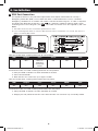
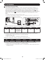
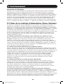
EPO Port Connection
This optional feature is only for those applications that require connection to a facility’s
Emergency Power Off (EPO) circuit. When the UPS is connected to this circuit, it enables
emergency shutdown of its inverter and inhibits transfer to internal bypass. A cable is required
to connect the EPO port of the UPS (see
2a
) to a normally closed or normally open switch
according to the circuit diagram (see
2b
). The cable and switch must be supplied by the user.
Notes:
1. The cable should not have a resistance greater than 5 ohms.
2. If a non-latching EPO switch is used, the EPO must be held for a minimum of 1 second. This does not
apply to a latching EPO switch.
UPS Unit State when asserting EPO with AC line present:
LEDs Output Fans Serial SNMP USB
OFF OFF ON (if in
frequency
conversion
mode)
ON ON ON
To restart the UPS unit after asserting EPO with AC line present:
1. Verify the EPO assertion has been removed or cleared.
2. Press the ON button
3. Now the UPS will start back up in Bypass mode.
UPS Unit State when asserting EPO without AC line power:
LEDs Output Fans Serial SNMP USB
OFF OFF OFF OFF OFF OFF
To restart the UPS unit after asserting EPO without AC line power:
1. Verify the EPO assertion has been removed or cleared.
2. Reapply AC line power to the UPS unit. Now the UPS will start back up in Standby mode.
4-5
2a 2b
18-09-247-933652.indb 8 2/13/2019 3:27:29 PM

9
4. Installation
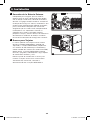
3
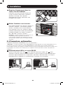
External Battery Connection
Check to ensure the external batteries being
connected match the voltage listed on the UPS
battery connector. Adding external batteries will
increase recharge time as well as runtime. See
the battery pack owner's manual for complete
installation instructions. Make sure cables are
fully inserted into their connectors. Small sparks
may result during battery connection; this is
normal. Do not connect or disconnect battery
packs when the UPS is running on battery power.
4
Accessory Card Slot
The slot accommodates an optional internal
accessory card (model WEBCARDLX, sold
separately). WEBCARDLX provides an Ethernet
network interface for remote monitoring and
control of the UPS system via SNMP, Web or
telnet. WEBCARDLX enables remote reboots,
shutdowns, load monitoring, condition reporting
and more.
Remove the cover panel from the slot to insert
the accessory card. Refer to the WEBCARDLX
documentation for additional installation
instructions.
3
4
18-09-247-933652.indb 9 2/13/2019 3:27:29 PM

10
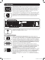
5.1 Front Panel Switches
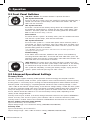
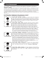
“ON/TEST” Button: This button controls 5 separate functions:
UPS System Power ON
To turn on the UPS system, press the “ON/TEST” button for approximately 1
second until the UPS system beeps, then release the button. The “ON
LINE” LED will illuminate.
UPS System Self-Test
To initiate a self-test of the battery during normal on-line operation, press
this button for approximately 1 second until the UPS system beeps, then
release it. The UPS system will transfer to battery power for 10 seconds.
Note: All LEDs illuminate during a self-test.
Alarm Silence
To silence the UPS system’s on battery alarm, press this button and hold it
until the UPS system beeps, then release the button.
UPS System Cold Start
To use the UPS system as a stand-alone power source when AC power is
unavailable (i.e. during a blackout), press this button once and hold it until
the UPS system beeps, then release the button. The UPS system will then
provide battery power to its outlets.*
* The “ON BATT” indicator light will be illuminated since the UPS system will be
operating from battery power.
Troubleshooting
If the "FAULT" LED illuminates, determine the specific fault condition by
activating the error code LEDs. To activate the error code LEDs, press the
"ON/TEST" button until the UPS system beeps, then release the button. The
error code LEDs will illuminate for 5 seconds.
“OFF” Button: This button places the UPS into Bypass mode. Press this
button and hold it until the UPS system beeps, then release it. The battery
will continue to charge and the fan will continue to operate. To turn the
UPS system off completely, including the battery charger, unplug the UPS
system’s power cord after pressing the “OFF” switch.
5.2 Advanced Operational Settings
Economy Mode
The UPS system supports economy mode operation to reduce energy consumption and BTU
emissions. In economy mode, the UPS system operates with increased efficiency when the quality
of utility power is satisfactory to pass through to connected equipment without double conversion.
Economy mode saves energy by suspending double conversion when incoming voltage is within
-10%/+10% of the nominal voltage setting. If the nominal voltage setting is 230V, the UPS system
will remain in economy mode while utility line voltage is between approximately 207V and 253V. If
utility line voltage falls outside this range, the UPS system will either switch back to standard
on-line, double conversion mode or it will switch to battery backup mode, depending on the
severity of the voltage deviation.
Economy mode may be enabled (or disabled) through PowerAlert software or the optional WEBCARDLX
internal accessory card. The UPS system's yellow “BYPASS” LED will illuminate continuously when
economy mode is enabled. Refer to the PowerAlert or WEBCARDLX documentation for more information.
On-line, double-conversion mode (default)
Typical line efficiency at full load: 92%
Output voltage range: ± 2% of nominal setting (200/208/220/230/240V)
Economy mode
Typical line efficiency at full load: 97%
Output voltage range: -10%/+10% of nominal setting (200/208/220/230/240V)
5. Operation
18-09-247-933652.indb 10 2/13/2019 3:27:30 PM

11
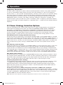
Frequency Conversion
The UPS system automatically selects 50 Hz or 60 Hz operation based on utility power conditions
at start-up and provides output power that tracks the input frequency as long as the frequency
remains within +/- 5% Hz of the selected frequency. The UPS system also has an advanced setting
that allows continuous frequency conversion from 50 Hz to 60 Hz or from 60 Hz to 50 Hz. The
advanced frequency conversion setting is accessible through PowerAlert software or the optional
WEBCARDLX internal accessory card. When continuous frequency conversion is enabled, the
maximum output capacity of the UPS system is derated by 30%. In frequency conversion mode or
battery backup mode, the output frequency is regulated within +/- 0.05 Hz of the selected nominal
frequency.
5. Operation
5.3 Power Strategy Selection Options
Tripp Lite SmartOnline UPS systems offer several built-in power strategy options that enable the
UPS to optimize performance to meet user needs for MAXIMUM POWER QUALITY, MAXIMUM
EFFICIENCY, and FREQUENCY REGULATION or FREQUENCY CONVERSION operation. The default
AUTO-ADAPTIVE power strategy combines the benefits of high-efficiency and maximum power
quality. Each power strategy option enables the UPS to automatically shift between specific
operating modes as power and UPS status dictates. Available power strategy options include:
Auto-Adaptive Power Strategy (Default from factory)
Enables the UPS to automatically switch between ONLINE MODE and ECONOMY MODE as dictated
by the quality and reliability of UPS input power. If the UPS does not experience a power failure in a
week’s time (not including UPS self-test) the UPS will automatically switch to ECONOMY MODE. If a
power failure occurs, the UPS will maintain output in BATTERY MODE. When power is restored, the
UPS will repeat the cycle by running in ONLINE MODE until there are no power failures for one
week.
Max Efficiency Power Strategy
Enables the UPS to run continuously in ECONOMY MODE any time incoming AC power is within the
configured bypass low/high voltage range. If UPS input voltage is outside the configured bypass
range, the UPS will automatically switch to ONLINE MODE until AC input voltage is restored within
the configured bypass voltage range. This is similar to Auto-Adaptive Power Strategy, except transfer
to ECONOMY MODE is immediate as voltage levels recover. There is no one-week time period of
power-failure-free operation required in order for the UPS to return to ECONOMY MODE operation.
Max Quality Power Strategy
Enables the UPS to run continuously in ONLINE MODE the entire time incoming AC power is within
the range for online mode operation. The UPS will remain operating continuously in Online Double-
Conversion mode, providing the highest quality output power with zero transfer time. Auto-bypass
mode is available during UPS failure modes when AC input is within the bypass range.
Frequency Regulation Power Strategy
Similar to Max-Quality Power Strategy, except the UPS will actively regulate output frequency within
+/-0.05Hz of the 50 or 60Hz nominal frequency measured on startup. The UPS will remain
operating continuously in Online Double-Conversion mode, providing the highest quality output
power with zero transfer time. Auto-bypass mode is available during UPS failure modes when AC
input is within the bypass range.
Frequency Conversion to 60Hz & Frequency Conversion to 50Hz Power Strategies
Similar to Max Quality power strategy, except the UPS will actively regulate output within +/-0.05Hz
of the 50Hz (Freq. Conv. to 50Hz setting) or 60Hz (Freq. Conv. to 60Hz setting). Auto-bypass is not
available in FREQUENCY CONVERSION mode. Typical applications include converting 50 to 60Hz
(or 60 to 50Hz) for sensitive electronic devices.
Note: Maximum power supported in Frequency Regulation/Conversion modes is derated by 30%.
18-09-247-933652.indb 11 2/13/2019 3:27:30 PM

12
5.4 Front Panel Indicator Lights
Note: All LEDs illuminate during a UPS system self-test.
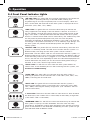
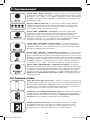
“ON LINE” LED: This green LED will illuminate continuously to indicate the
UPS system is operating normally in ON-LINE mode (filtering and
resynthesizing AC line input to provide pure sine wave output). When this
LED is illuminated, the load level of the UPS system is displayed on the %
level LEDs (25%, 50%, 75%, 100%).
“LINE” LED: This green LED will illuminate continuously to indicate the
utility-supplied AC line voltage at the wall outlet is nominal. It will flash if
the line voltage is outside the nominal bypass range (either too low or too
high). User action is not required when the LED flashes; the UPS system
remains in normal online mode and will continuously and automatically filter
AC line power to provide equipment with pure sine wave AC power,
regardless of brownout or overvoltage conditions. If this LED is off, then AC
line voltage is not present (blackout) or is at an extremely high voltage, and
the UPS system will provide connected equipment with power from its
battery system.
“BYPASS” LED: This yellow LED will illuminate continuously when the UPS
system is in economy mode. The LED will flash when the UPS system is in
BYPASS mode, indicating that the UPS system’s DC/AC inverter is
deactivated. The red “FAULT” LED will also illuminate if the UPS system is in
BYPASS mode due to a fault. During normal operation, the BYPASS LED will
illuminate briefly when the unit is plugged in. If an internal fault or overload
occurs, the LED will flash repeatedly to show that connected equipment will
receive filtered AC line power, but will not receive battery power during a
blackout. In this case, contact Tripp Lite for service.
“FAULT” LED: This red LED will flash when the UPS system detects an
internal fault. If the condition persists after restarting the UPS system, see
Section 6: Troubleshooting.
“LOAD” LED: This green LED will illuminate when the UPS system is
receiving AC power. It also illuminates the % level LEDs (25%, 50%, 75%,
100%) indicating the UPS load level.
“BATT” LED: This green LED will illuminate when the UPS system is
operating from battery power. It illuminates the % level LEDs (25%, 50%,
75%, 100%) indicating the battery charge level. (The “ON BATT” LED will
also be illuminated.)
% Level LEDs: These dual-function LEDs will indicate the % level for either
the load level (if the “LOAD” LED is illuminated) or the battery charge level
(if the “BATT” LED is illuminated).
“OVERLOAD” LED: This red LED will illuminate continuously to indicate the
UPS system’s capacity has been exceeded. The UPS alarm will beep
continuously. Immediately unplug some equipment until the LED and alarm
go off. If the overload is not corrected immediately, the UPS system will go
from ON-LINE mode to BYPASS mode.
5. Operation
18-09-247-933652.indb 12 2/13/2019 3:27:30 PM

13
“BATT LOW” LED: This yellow LED will illuminate when the UPS system’s
battery charge level is low. The UPS alarm will beep until the batteries are
either depleted or adequately recharged.
“ON BATT” LED: This green LED will illuminate continuously to indicate AC
line voltage is absent (or out of range) and the UPS system is providing
equipment with battery-derived AC power. The UPS system will also beep
every 2 seconds (unless silenced by the “ON/TEST” button) and the % level
LEDs (25%, 50%, 75%, 100%) will display the battery charge level.
“REPLACE BATT” LED: This red LED as well as the red “FAULT” LED will
illuminate continuously and the UPS alarm will beep every 2 seconds if the
UPS system fails the automatic self-test. Allow the UPS system to charge
for at least 12 hours and perform a self-test as described in Section 5.1:
Front Panel Switches. If the condition persists, contact Tripp Lite.
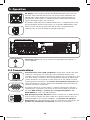
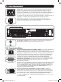
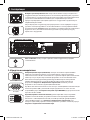
5.5 Rear Panel
Accessory Card Slot: Remove the cover panel from this slot to install an
optional internal WEBCARDLX accessory, sold separately. WEBCARDLX
provides a network interface for monitoring and control via SNMP, Web or
telnet, enabling remote reboots, shutdowns and more.
External Battery Pack Connector: This UPS system supports the use of
optional Tripp Lite external battery packs for additional runtime. See
Section 1.2: Optional Accessories for compatible models and limitations.
Input Power Inlet: This UPS system requires a user-supplied power cord.
This power cord should have an IEC-320-C19 connector on one end and a
plug appropriate for the local site’s utility outlet on the other end.
IEC-320-C20
5. Operation
18-09-247-933652.indb 13 2/13/2019 3:27:31 PM

14
5.6 Communications
Communication Ports (USB and RS232): These ports connect the UPS
system to a computer. Use with Tripp Lite’s PowerAlert software and
included cabling to allow the computer to automatically save open files and
shut down during a blackout. Also use PowerAlert software to control UPS
system load banks and monitor a wide variety of AC line power and UPS
system operating conditions. See Section 4.4: Optional Connections for
cable connection instructions. Refer to the PowerAlert documentation for
software installation instructions.
The RS232 port may also be used as a contact closure port. The port’s
numbered pin assignments are shown in the RS232 (DB9) illustration at
left. See DB9 Settings in Section 5.7: Configuration Options via
WEBCARDLX for a full list of DB9 features.
EPO (Emergency Power Off) Port: The UPS system has an EPO port that
may be used to connect the UPS system to a contact closure switch to
enable emergency UPS system shutdown. See Section 4.4: Optional
Connections for more information. After re-connecting to utility power, see
Section 4.3: Connection and Start-Up for start-up instructions.
AC Outlets: These outlets provide connected equipment with pure sine
wave AC output derived from the AC line during normal operation and
derived from battery power during blackouts and severe brownouts or
overvoltages. Output power is filtered to protect connected equipment
against damaging surges and line noise.
The outlets are divided into numbered load banks, as labelled on the unit.
Using PowerAlert software and cabling, or an optional WEBCARDLX, load
banks may be individually turned off and on from a remote location,
allowing users to reset or reboot connected equipment.
CONTROLLABLE LOAD 1
CONTROLLABLE LOAD 2
RS232 (DB9)
Grounding Screw: Use this to connect any equipment that requires a
chassis ground.
5. Operation
IEC-320-C19
IEC-320-C13
USB
18-09-247-933652.indb 14 2/13/2019 3:27:32 PM

15
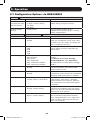
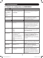
5.7 Configuration Options via WEBCARDLX
CONTROL DEVICE
Setting Value(s) Description
Auto Batt. Testing
(Set regular battery
self-test interval)
• Disable
• 4 weeks (factory setting)
• 13 weeks
• 26 weeks
Use this option to initiate automatic UPS
battery testing at regular intervals.
Reset to Factory
Settings
• Factory Reset Use this option to reset all UPS
preferences to factory settings, including
battery configurations.
CONFIGURATION DEVICE SETTINGS DEVICE PROPERTIES
Property Value(s) Description
Audible Alarm • Enable
• Disable
Audible Alarm DISABLE setting prevents
power fail and operating fault alarms only;
the UPS will always “beep” to confirm the
UPS is accepting user input.
Output Voltage • 200
• 208
• 220
• 230
• 240
Use this option to set the nominal UPS
output voltage (changes take effect on
next restart).
Power Strategy • Auto-Adaptive (factory setting)
• Max Efficiency
• Max Quality
• Freq. Regulation
• Freq. Conversion to 60Hz
• Freq. Conversion to 50Hz
Use this option to set the UPS Power
strategy.
See Section 5.3: Power Strategy
Selection Options under Operations
for more info on available Power Strategy
options.
Cold Start • Enable (factory setting)
• Disable
Enabling Cold Start allows the UPS to be
manually turned on into battery mode
during a power failure.
Auto-Restart • Enable (factory setting)
• Disable
Enabling Auto-Restart allows the UPS to
automatically turn back on into a protected
operating mode when power is restored.
Auto-Restart Delay • Enter: 0 to 60 seconds
(factory setting is 0 seconds)
Auto-Restart delay forces the UPS to wait
0-60 seconds after power is restored
before automatically restarting. Requires
that Auto-restart be enabled when power
is restored.
Energy Saving • Enter: 0-100%
• Disable (factory setting)
Energy Saving enables the UPS to
automatically shutdown when the output
load is less than the selected percentage
continuously for 5 minutes.
Off Mode • Standby
• Bypass (factory setting)
Off Mode setting of BYPASS allows the
UPS to provide unregulated line power
within configured bypass low / high limits
to be available at the output of the UPS
when it is turned off.
5. Operation
18-09-247-933652.indb 15 2/13/2019 3:27:33 PM

16
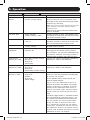
CONFIGURATION DEVICE SETTINGS DEVICE PROPERTIES
Property Value(s) Description
Min. Batt to
Restart
• Enter: 10-90%
• Disable (factory setting)
Minimum battery charge level to restart
forces the UPS to wait until batteries have
recharged to the selected percentage before
automatically restarting.
Note: UPS can be manually started using the power
button if battery is below the minimum battery
restart threshold.
Requires that Auto-restart be enabled when
power is restored.
Low Batt. Alert • Enter: 10-90%
(factory setting is 20%)
Enables the UPS to send a low-battery alert
as batteries discharge to the selected charge
level during a power failure.
Timed Shutdown • Enter a time interval
(mm:ss)
Timed Shutdown sets the maximum amount
of battery runtime in seconds or minutes the
UPS will provide during a power failure.
Timed Shutdown • Enable/Disable
(factory setting)
Use the DISABLE setting for the longest
possible battery runtime.
Shutdown
Completion
• Required (factory setting)
• Interrupt OK
The UPS will communicate shutdown
messaging to connected systems prior to
UPS shutdown. The setting of INTERRUPT OK
will interrupt shutdown messaging if power is
restored after shutdown messaging is sent.
DB9 Settings
(Output pins 1&5)
• On battery (factory setting)
• On bypass
• Output on
• Low battery
The UPS will signal the selected condition by
shorting pins 1&5 on the DB9 port.
DB9 Settings
(Output pins 8&5)
• On battery
• On bypass
• Output on
• Low battery (factory setting)
The UPS will signal the selected condition by
shorting pins 8&5 on the DB9 port.
DB9 Settings
(Input pins 3&9)
• Shutdown (factory setting)
• Output off
• Reboot
• Output on
• Power Toggle
The UPS will perform the selected action
when pins 3&9 are shorted on the DB9 port
for at least 3.8 seconds.
For the Reboot option (output off for 30
seconds before reboot):
The pins must be shorted for at least 3.8
seconds to perform the reboot. The reboot
happens at exactly 3.8 seconds. If the pins
continue to be shorted for more than 3.8
seconds, no further action should be taken.
The UPS takes no action on release of the
short.
The Power Toggle option is intended to keep
the unit powered on whenever the pins are
not shorted and powered off whenever the
pins are shorted. This input cannot power
on the unit from an off state unless valid
AC is applied (this function will not impose
a cold start). To power on, the pins must be
not shorted for at least 3.8 seconds and AC
must be valid. To power off, the pins must be
shorted for at least 3.8 seconds.
5. Operation
18-09-247-933652.indb 16 2/13/2019 3:27:33 PM

17
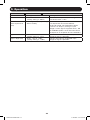
CONFIGURATION DEVICE SETTINGS DEVICE THRESHOLDS
Threshold Value(s) Description
Overload Alert Lvl. • Enter: 5-105%
(factory setting is 100%)
Sets the UPS output load percentage before
an overload alert is sent.
Conf. Fault Action
(UPS response to
fault)
• Go to bypass (factory setting)
• Go to standby
Sets the UPS response to fault conditions
that require the UPS to exit double-
conversion mode. GO TO BYPASS option
maintains AC output (so long as input
voltage is within bypass high/low limits). GO
TO STANDBY option causes the UPS to turn
off output AC in response to fault conditions.
Bypass Low Limit • Enter: -5% to -20%
(factory setting is -15%)
Specifies the lowest acceptable input
voltage for bypass operation.
Bypass High Limit • Enter: +5% to +20%
(factory setting is +10%)
Specifies the highest acceptable input
voltage for bypass operation.
5. Operation
18-09-247-933652.indb 17 2/13/2019 3:27:33 PM

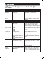
18
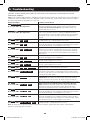
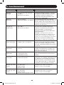
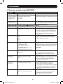
The UPS system control panel LEDs will illuminate in the sequences listed below to indicate
operational problems.
Note: If the “FAULT” LED illuminates, determine the specific fault condition by activating the error code LEDs. To
activate the error code LEDs, press the “ON/TEST” button until the UPS system beeps, then release the button.
The error code LEDs will illuminate for 5 seconds.
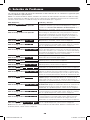
Illuminated LEDs Condition and Solution
On: REPLACE BATT
Error Code LEDs: Not Applicable
Replace Battery: Allow the UPS system to charge for at least
12 hours and perform a UPS system self-test as described in
Section 5.1: Front Panel Switches. If the LED remains on,
contact Tripp Lite for service.
Flashing: LINE
Error Code LEDs: Not Applicable
Input Abnormal: Utility power voltage or frequency is too high
or too low for the UPS system to operate in BYPASS mode. If
an inverter failure occurs, the UPS system will not pass through
utility power to the outlets and any connected equipment will
turn off.
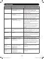
On: FAULT
Error Code LEDs: 50% 100%
Battery Weak: Allow the UPS system to charge for 12 hours. If
the LED remains on, contact Tripp Lite for service.
On: FAULT
Error Code LEDs: 25% 50%
Inverter Over-Current: Reduce the load supported by the UPS
system by unplugging some equipment. Restart the UPS system.
If the problem persists, contact Tripp Lite for service.
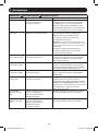
On: FAULT
Error Code LEDs: 25% 75% 100%
Internal Temperature Too High: Confirm that adequate space
exists for air to circulate near the UPS system’s vents. Confirm
the UPS system’s fan is working properly. Confirm the ambient
temperature does not exceed recommended levels. Restart the
UPS system.
On: FAULT
Error Code LEDs: 25% 75%
Inverter Overload: Reduce the load supported by the UPS
system by unplugging some equipment.
On: FAULT
Error Code LEDs: 25% 50% 100%
Charger Out of Order: Restart the UPS system. If the problem
persists, contact Tripp Lite for service.
On: FAULT
Error Code LEDs: 25% 50% 75%
Fan Out of Order: Restart the UPS system. If the problem
persists, contact Tripp Lite for service.
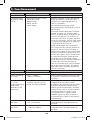
On: FAULT
Error Code LEDs: 25% 50% 75% 100%
Bypass Phase Can’t Lock: Restart the UPS system. If the
problem persists, contact Tripp Lite for service.
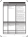
On: FAULT
Error Code LEDs: BATT 75% 100%
Wiring Fault: Check the utility line for wiring problems such as
reversed line and neutral or a missing ground. The UPS system
will detect some (but not all) wiring faults. Contact an electrician
to verify the AC input wiring.
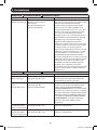
On: FAULT
Error Code LEDs: BATT 25%
Utility Voltage Low and Battery Disconnected at
Initialization: Shut down the UPS system. Check the internal
battery connections. Correct the AC input voltage. Restart the
UPS system. If the problem persists, contact Tripp Lite for service.
On: FAULT
Error Code LEDs: BATT 25% 100%
Utility Voltage Low and Battery Disconnected in On-Line
Mode: Shut down the UPS system. Check the internal battery
connections. Correct the AC input voltage. Restart the UPS
system. If the problem persists, contact Tripp Lite for service.
On: FAULT
Error Code LEDs: BATT 25% 75%
Input Over-Current: Reduce the load supported by the UPS
system by unplugging some equipment. Restart the UPS system.
If the problem persists, contact Tripp Lite for service.
On: FAULT
Error Code LEDs: BATT 25% 50%
Bypass Overload: Reduce the load supported by the UPS
system by unplugging some equipment. Either wait for the UPS
system to recognize the load reduction or restart the UPS system.
If the problem persists, contact Tripp Lite for service.
On: FAULT
Error Code LEDs: BATT 25% 50% 100%
Battery Voltage Too High: Restart the UPS system. If the
problem persists, contact Tripp Lite for service.
Note: All other error codes may indicate internal fault conditions. Restart the UPS system. If the problem
persists, contact Tripp Lite for service.
6. Troubleshooting
18-09-247-933652.indb 18 2/13/2019 3:27:33 PM

19
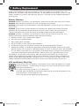
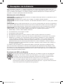
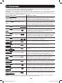
7. Battery Replacement
Under normal conditions, the original batteries in the UPS system will last several years. The
batteries are designed for hot-swap replacement (i.e. replacement while the UPS system is in ON
mode). Batteries may also be replaced when the UPS is switched off and supported equipment is
disconnected.
Battery Warnings
CAUTION: Batteries can present a risk of electrical shock and burn from high short-circuit current.
CAUTION: Do not dispose of batteries in a fire. The batteries may explode.
CAUTION: Do not open or mutilate batteries. Released electrolyte is harmful to the skin and eyes. It
may be toxic.
CAUTION: There are no user-serviceable parts inside the UPS. Battery replacement should be
performed only by authorized service personnel using the same number and type of batteries
(Sealed Lead-Acid). Unplug and turn off the UPS before performing battery replacement.
CAUTION: A battery can present a risk of electrical shock and high short-circuit current. The
following precautions should be observed when working on batteries:
a) Remove watches, rings, or other metal objects.
b) Use tools with insulated handles.
c) Wear rubber gloves and boots.
d) Do not lay tools or metal parts on top of batteries.
e) Disconnect charging source prior to connecting or disconnecting battery terminals.
f) Determine if battery is inadvertently grounded. If inadvertently grounded, remove source from
ground. Contact with any part of a grounded battery can result in electrical shock. The likelihood
of such shock can be reduced if such grounds are removed during installation and maintenance
(applicable to equipment and remote battery supplies not having a grounded supply circuit).
The batteries are recyclable. Refer to local codes for disposal requirements or visit http://www.
tripplite.com/support/recycling-program for recycling information. Tripp Lite offers a complete line
of UPS System Replacement Battery Cartridges (R.B.C.).Visit Tripp Lite on the Web at http://www.
tripplite.com/products/battery-finder/ to locate the specific replacement battery for your UPS.
UPS and Battery Recycling
Please recycle Tripp Lite Products. The batteries used in Tripp Lite products are sealed
Lead-Acid batteries. These batteries are highly recyclable. Please refer to local codes
for disposal requirements.
Call Tripp Lite for recycling info at 1.773.869.1234.
Go to the Tripp Lite Website for up-to-date information on recycling the batteries or any
Tripp Lite product. Please follow this link:
http://www.tripplite.com/support/recycling-program/
18-09-247-933652.indb 19 2/13/2019 3:27:33 PM

20
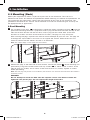
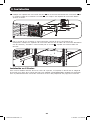
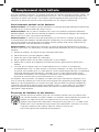
3
4
2
1
7. Battery Replacement
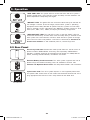
3
Open the front plate.
Disconnect battery power
cable.
4
Remove old battery pack.
Procedure
1
Remove the four front
screws from the front bezel
and take it off.
2
Loosen the two screws
securing the front plate.
18-09-247-933652.indb 20 2/13/2019 3:27:35 PM
Page is loading ...
Page is loading ...
Page is loading ...
Page is loading ...
Page is loading ...
Page is loading ...
Page is loading ...
Page is loading ...
Page is loading ...
Page is loading ...
Page is loading ...
Page is loading ...
Page is loading ...
Page is loading ...
Page is loading ...
Page is loading ...
Page is loading ...
Page is loading ...
Page is loading ...
Page is loading ...
Page is loading ...
Page is loading ...
Page is loading ...
Page is loading ...
Page is loading ...
Page is loading ...
Page is loading ...
Page is loading ...
Page is loading ...
Page is loading ...
Page is loading ...
Page is loading ...
Page is loading ...
Page is loading ...
Page is loading ...
Page is loading ...
Page is loading ...
Page is loading ...
Page is loading ...
Page is loading ...
Page is loading ...
Page is loading ...
Page is loading ...
Page is loading ...
Page is loading ...
Page is loading ...
Page is loading ...
Page is loading ...
Page is loading ...
Page is loading ...
Page is loading ...
Page is loading ...
Page is loading ...
Page is loading ...
Page is loading ...
Page is loading ...
Page is loading ...
Page is loading ...
Page is loading ...
Page is loading ...
Page is loading ...
Page is loading ...
Page is loading ...
Page is loading ...
Page is loading ...
Page is loading ...
Page is loading ...
Page is loading ...
-
 1
1
-
 2
2
-
 3
3
-
 4
4
-
 5
5
-
 6
6
-
 7
7
-
 8
8
-
 9
9
-
 10
10
-
 11
11
-
 12
12
-
 13
13
-
 14
14
-
 15
15
-
 16
16
-
 17
17
-
 18
18
-
 19
19
-
 20
20
-
 21
21
-
 22
22
-
 23
23
-
 24
24
-
 25
25
-
 26
26
-
 27
27
-
 28
28
-
 29
29
-
 30
30
-
 31
31
-
 32
32
-
 33
33
-
 34
34
-
 35
35
-
 36
36
-
 37
37
-
 38
38
-
 39
39
-
 40
40
-
 41
41
-
 42
42
-
 43
43
-
 44
44
-
 45
45
-
 46
46
-
 47
47
-
 48
48
-
 49
49
-
 50
50
-
 51
51
-
 52
52
-
 53
53
-
 54
54
-
 55
55
-
 56
56
-
 57
57
-
 58
58
-
 59
59
-
 60
60
-
 61
61
-
 62
62
-
 63
63
-
 64
64
-
 65
65
-
 66
66
-
 67
67
-
 68
68
-
 69
69
-
 70
70
-
 71
71
-
 72
72
-
 73
73
-
 74
74
-
 75
75
-
 76
76
-
 77
77
-
 78
78
-
 79
79
-
 80
80
-
 81
81
-
 82
82
-
 83
83
-
 84
84
-
 85
85
-
 86
86
-
 87
87
-
 88
88


Tripp Lite SUINT3000RTXL2U Owner's manual
- Type
- Owner's manual
Ask a question and I''ll find the answer in the document
Finding information in a document is now easier with AI
in other languages
Related papers
-
Tripp Lite SU3000RTXL2U Owner's manual
-
-
-
-
-
-
-
-
-
Other documents
-
Legrand Online-UPS-1-3KVA-I-00884 Owner's manual
-
 OPTI-UPS DS1000D User manual
-
Legrand Line-Interactive-UPS-1-3KVA-I-00886 Owner's manual
-
Sunforce 200Watt POWER INVERTER User manual
-
Sven Pro 650 (LCD, USB) User manual
-
-
OPTI-UPS DS3000B-RM User manual
-
Dynex DX-800U User manual
-
APC SRT2200XLA Installation guide
-
 Best Power Patriot Pro II 750 VA User guide

