Toro Hydraulic Angle, Power Rake TXL 2000 Tool Carrier Installation guide
- Category
- Wall & ceiling mounts accessories
- Type
- Installation guide

FormNo.3425-990RevD
HydraulicAngle
PowerRakeTXL2000ToolCarrier
ModelNo.22537
InstallationInstructions
Installation
LooseParts
Usethechartbelowtoverifythatallpartshavebeenshipped.
Description
Qty.
Use
Nopartsrequired
–
Preparethemachine.
Manifoldassembly
1
Bolt(3/8x1inch)
3
Lockwasher3
Flatwasher3
Hoseclamp1
Bolt(5/16x1-1/2inches)
1
Longhose1
Shorthose
1
Hydrauliccylinderassembly1
Pivotpin2
Snapring
4
Largewasher4
Shortwireharness
1
Longwireharness1
Installthehydraulicangle.
Nopartsrequired
–
Completetheinstallation.
PreparingtheMachine
Important:Thiskitrequirestheinstallationof
theauxiliarywireharnesskitandthepowerrake
beforeinstallation.
Note:Determinetheleftandrightsidesofthe
machinefromthenormaloperatingposition.
1.Parkthetractionunitonalevelsurface.
2.Disengagetheauxiliaryhydraulics.
3.Loweranyequippedattachments;refertoyour
Operator’sManual.
4.Engagethetractionunitparkingbrake.
5.Shutoffthetractionunitengineandremovethe
key.
6.Waitforthetractionunittocool.
7.Disconnectthetractionunitbattery;refertoyour
Operator’sManual.
©2019—TheToro®Company
8111LyndaleAvenueSouth
Bloomington,MN55420
Registeratwww.T oro.com.
OriginalInstructions(EN)
PrintedintheUSA
AllRightsReserved
*3425-990*D

InstallingtheHydraulic
Angle
Important:Youmaydiscardallremovedparts
unlessotherwisenoted.
WARNING
Seekimmediatemedicalattentionifuidis
injectedintoskin.Injecteduidmustbe
surgicallyremovedwithinafewhoursbya
doctor.
•Ensurethatallhydraulic-uidhoses
andlinesareingoodconditionandall
hydraulicconnectionsandttingsaretight
beforeapplyingpressuretothehydraulic
system.
•Keepyourbodyandhandsawayfrom
pinholeleaksornozzlesthateject
high-pressurehydraulicuid.
•Usecardboardorpapertondhydraulic
leaks.
•Safelyrelieveallpressureinthehydraulic
systembeforeperforminganyworkonthe
hydraulicsystem.
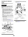
1.Markeachofthehosesasleftorright(fromthe
operator’sposition).
2.Removethenutandboltsecuringthehose
clamptothehosemount(Figure1).
3.Disconnectthepowerrakemotorhosesfromthe
attachmenthosesattheangletting(Figure1).
g270391
Figure1
1.Attachmenthoses3.Powerrakemotorhoses
2.Hoseclamp
4.Installthemanifoldassemblytothehosemount
with3bolts(3/8x1inch),lockwashersandat
washers(Figure2).
g270540
Figure2
Somepartsnotshownforclarity
1.Bolt(3/8x1inch)4.Manifoldassembly
2.Lockwasher5.Hosemount
3.Flatwasher
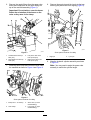
5.Installtheattachmenthosesdirectlytothe
straightttingsintherearofthemanifold
assembly(Figure3).
2

6.Removetheanglettingsfromthepowerrake
hosesandinstallthemtotheanglettingson
topofthemanifoldassembly(Figure3).
Important:Donottwistorcrossthehoses.
Retaintheorientationofthehosesonthe
valveastheywereintheclamp.
g284900
Figure3
1.Leftattachmenthose(in
REVport)
3.Leftpowerrakemotor
hose(inM2port)
2.Rightattachmenthose(in
FWDport)
4.Rightpowerrakemotor
hose(inM1port)
7.Installthehoseclampandroutethehosesunder
themanifoldasshowninFigure4andFigure6.
g270507
Figure4
Somepartsnotshownforclarity
1.Bolt(5/16x1-1/2inches)3.Shorthose(inlower
manifoldtting)
2.Hoseclamp
4.Longhose(inupper
manifoldtting)
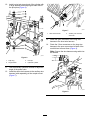
8.Removetheanglepinandthelynchpinthatare
securingthepowerrakefromangling(Figure5).
g285356
Figure5
Somepartsnotshownforclarity
1.Anglepin2.Lynchpin
9.Alignthehydrauliccylinderassemblyasshown
inFigure6.
Note:Youmayneedtoanglethepowerrake
manuallytomatchthecylinderlength.
3

10.Installapivotpinateachendofthecylinderwith
2largewashersandsnapringsateachendof
thepivotpins(Figure6).
g285333
Figure6
1.Snapring
3.Pivotpin
2.Largewasher4.Hydrauliccylinder
11.Usetheauxiliaryhydrauliccontrolstoadjustthe
angleofthepowerrake.
12.Installtheshortwireharnesstotheauxiliarywire
harness(soldseparately)atthecouplermount
(Figure7).
g284377
Figure7
1.Shortwireharness
2.Auxiliarywireharness
connector
13.Installtheopenconnectorofthelongwire
harnesstotheshortwireharness.
14.Routethe2freeconnectorsonthelongwire
harnesstotheopenconnectorsleftsideofthe
manifoldandconnectthem(Figure8).
Note:Securethewireharnessusingcableties
asneeded.
g284443
Figure8
4

CompletingtheInstallation
1.Tightenallofthehoseconnections.
2.Lubricatethecylindergreasettings;referto
LubricatingtheHydraulicAngle(page5).
3.Connectthetractionunitbattery;refertoyour
tractionunitOperator’sManual.
4.Turnonthetractionunitandtestthehydraulic
angleoperation.
Important:Tooperatethecylinder,ow
mustberunningtotheattachment.While
owisrunning,operatethecylinderusing
thesecondaryattachmentfunctiononthe
joystick.
Note:Ifthehydraulicangleisnotoperating
correctly,ensurethatthehosesareconnected
tothecorrectports.
5.Ifanyhydraulicuidwasspilled,ensurethatthe
tractionunithydraulicuidisatthecorrectlevel;
refertoyourOperator’sManual.
6.Usetheauxiliaryhydrauliccontrolstoadjustthe
angleofthepowerrake.
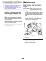
Maintenance
LubricatingtheHydraulic
Angle
ServiceInterval:Beforeeachuseordaily—(and
immediatelyaftereverywashing)
GreaseType:General-purposegrease.
1.Parkthetractionunitonalevelsurface,engage
theparkingbrake,andlowertheloaderarms.
2.Shutoffthetractionunitengineandremovethe
key.
3.Cleanthegreasettingswitharag.
4.Connectagreaseguntothehydraulicangle
hingepingreasettings(Figure9).
g272055
Figure9
1.Greasettings
5.Pumpgreaseintothettingsuntilgreasebegins
tooozeoutofthebearings.
6.Wipeupanyexcessgrease.
5

Notes:

Notes:

-
 1
1
-
 2
2
-
 3
3
-
 4
4
-
 5
5
-
 6
6
-
 7
7
-
 8
8


Toro Hydraulic Angle, Power Rake TXL 2000 Tool Carrier Installation guide
- Category
- Wall & ceiling mounts accessories
- Type
- Installation guide
Ask a question and I''ll find the answer in the document
Finding information in a document is now easier with AI
Related papers
Other documents
-
Smithco Super Star E Owner's manual
-
-
Smithco Super Star Owner's manual
-
-
-
-
-
-
-