Supermicro X11SSH-GF-1585 User manual
- Category
- Server/workstation motherboards
- Type
- User manual
This manual is also suitable for

USER’S MANUAL
Revision 1.0a
X11SSH-GF-1585
X11SSH-GF-1585L
X11SSH-GTF-1585
X11SSH-GTF-1585L

The information in this User’s Manual has been carefully reviewed and is believed to be accurate. The vendor assumes
no responsibility for any inaccuracies that may be contained in this document, and makes no commitment to update
or to keep current the information in this manual, or to notify any person or organization of the updates. Please Note:
For the most up-to-date version of this manual, please see our website at www.supermicro.com.
Super Micro Computer, Inc. ("Supermicro") reserves the right to make changes to the product described in this manual
at any time and without notice. This product, including software and documentation, is the property of Supermicro and/
or its licensors, and is supplied only under a license. Any use or reproduction of this product is not allowed, except
as expressly permitted by the terms of said license.
IN NO EVENT WILL Super Micro Computer, Inc. BE LIABLE FOR DIRECT, INDIRECT, SPECIAL, INCIDENTAL,
SPECULATIVE OR CONSEQUENTIAL DAMAGES ARISING FROM THE USE OR INABILITY TO USE THIS PRODUCT
OR DOCUMENTATION, EVEN IF ADVISED OF THE POSSIBILITY OF SUCH DAMAGES. IN PARTICULAR, SUPER
MICRO COMPUTER, INC. SHALL NOT HAVE LIABILITY FOR ANY HARDWARE, SOFTWARE, OR DATA STORED
OR USED WITH THE PRODUCT, INCLUDING THE COSTS OF REPAIRING, REPLACING, INTEGRATING,
INSTALLING OR RECOVERING SUCH HARDWARE, SOFTWARE, OR DATA.
Any disputes arising between manufacturer and customer shall be governed by the laws of Santa Clara County in the
State of California, USA. The State of California, County of Santa Clara shall be the exclusive venue for the resolution
of any such disputes. Supermicro's total liability for all claims will not exceed the price paid for the hardware product.
FCC Statement: This equipment has been tested and found to comply with the limits for a Class A digital device
pursuant to Part 15 of the FCC Rules. These limits are designed to provide reasonable protection against harmful
interference when the equipment is operated in a commercial environment. This equipment generates, uses, and can
radiate radio frequency energy and, if not installed and used in accordance with the manufacturer’s instruction manual,
may cause harmful interference with radio communications. Operation of this equipment in a residential area is likely
to cause harmful interference, in which case you will be required to correct the interference at your own expense.
California Best Management Practices Regulations for Perchlorate Materials: This Perchlorate warning applies only
to products containing CR (Manganese Dioxide) Lithium coin cells. “Perchlorate Material-special handling may apply.
See www.dtsc.ca.gov/hazardouswaste/perchlorate”.
WARNING: Handling of lead solder materials used in this product may expose you to lead, a
chemical known to the State of California to cause birth defects and other reproductive harm.
The products sold by Supermicro are not intended for and will not be used in life support systems, medical equipment,
nuclear facilities or systems, aircraft, aircraft devices, aircraft/emergency communication devices or other critical
systems whose failure to perform be reasonably expected to result in signicant injury or loss of life or catastrophic
property damage. Accordingly, Supermicro disclaims any and all liability, and should buyer use or sell such products
for use in such ultra-hazardous applications, it does so entirely at its own risk. Furthermore, buyer agrees to fully
indemnify, defend and hold Supermicro harmless for and against any and all claims, demands, actions, litigation, and
proceedings of any kind arising out of or related to such ultra-hazardous use or sale.
Manual Revision 1.0a
Release Date: August 10, 2017
Unless you request and receive written permission from Super Micro Computer, Inc., you may not copy any part of this
document. Information in this document is subject to change without notice. Other products and companies referred
to herein are trademarks or registered trademarks of their respective companies or mark holders.
Copyright © 2017 by Super Micro Computer, Inc.
All rights reserved.
Printed in the United States of America

3
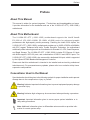
Preface
Preface
About This Manual
This manual is written for system integrators, IT technicians and knowledgeable end users.
It provides information for the installation and use of the X11SSH-GF/-GTF (-1585/-1585L)
motherboard.
About This Motherboard
The X11SSH-GF/-GTF (-1585/-1585L) motherboard supports the Intel® Xeon®
E3-1500 v5 (E3-1585 v5/65W; E3-1585L v5/45W) series for advanced graphic
performance and high-capacity media processing. Featuring the Intel® C236 chipset, the
X11SSH-GF/-GTF (-1585/-1585L) motherboard provides up to 64GB of DDR4 at 2400MHz
with ECC support. Enhanced with Intel's Trusted Execution Technology, the motherboard
additionally offers technologies such as Virtualization for Directed I/O, vPro, Smart Response,
and Rapid Storage. The X11SSH-GF/-GTF (-1585/-1585L) includes PCI Express 3.0 slots
with NVMe support, SATA 3.0 ports, and a combination of USB 3.0 and USB 2.0 ports. The
X11SSH-GF/-GTF (-1585/-1585L) also comes with a dedicated LAN port, which is supported
by the ASpeed AT2400 Baseboard Management Controller.
Please note that this motherboard is intended to be installed and serviced by professional
technicians only. For processor/memory updates, please refer to our website at http://www.
supermicro.com/products/.
Conventions Used in the Manual
Special attention should be given to the following symbols for proper installation and to prevent
damage done to the components or injury to yourself:
Warning! Indicates high voltage may be encountered when performing a procedure.
Warning! Indicates important information given to prevent equipment/property damage
or personal injury.
Important: Important information given to ensure proper system installation or to
relay safety precautions.
Note: Additional Information given to differentiate various models or provides infor-
mation for correct system setup.

4
Contacting Supermicro
Headquarters
Address: Super Micro Computer, Inc.
980 Rock Ave.
San Jose, CA 95131 U.S.A.
Tel: +1 (408) 503-8000
Fax: +1 (408) 503-8008
Email: [email protected] (General Information)
[email protected] (Technical Support)
Website: www.supermicro.com
Europe
Address: Super Micro Computer B.V.
Het Sterrenbeeld 28, 5215 ML
's-Hertogenbosch, The Netherlands
Tel: +31 (0) 73-6400390
Fax: +31 (0) 73-6416525
Email: [email protected] (General Information)
[email protected] (Technical Support)
[email protected] (Customer Support)
Website: www.supermicro.nl
Asia-Pacic
Address: Super Micro Computer, Inc.
3F, No. 150, Jian 1st Rd.
Zhonghe Dist., New Taipei City 235
Taiwan (R.O.C)
Tel: +886-(2) 8226-3990
Fax: +886-(2) 8226-3992
Email: [email protected]
Website: www.supermicro.com.tw
X11SSH-GF/-GTF (-1585/-1585L) User's Manual

5
Table of Contents
Chapter 1 Introduction
1.1 Checklist ...............................................................................................................................8
Quick Reference ...............................................................................................................11
Quick Reference Table ......................................................................................................12
Motherboard Features .......................................................................................................14
1.2 Processor and Chipset Overview .......................................................................................18
1.3 Special Features ................................................................................................................18
Recovery from AC Power Loss .........................................................................................18
1.4 System Health Monitoring ..................................................................................................19
Onboard Voltage Monitors ................................................................................................19
Fan Status Monitor with Firmware Control .......................................................................19
Environmental Temperature Control .................................................................................19
System Resource Alert......................................................................................................19
1.5 ACPI Features ....................................................................................................................20
1.6 Power Supply .....................................................................................................................20
1.7 Super I/O ............................................................................................................................20
1.8 Advanced Power Management ..........................................................................................21
Intel
®
Intelligent Power Node Manager (IPNM).................................................................21
Management Engine (ME) ................................................................................................21
Chapter 2 Installation
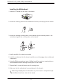
2.1 Static-Sensitive Devices .....................................................................................................22
Precautions .......................................................................................................................22
Unpacking .........................................................................................................................22
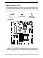
2.2 Motherboard Installation .....................................................................................................23
Tools Needed ....................................................................................................................23
Location of Mounting Holes ..............................................................................................23
Installing the Motherboard.................................................................................................24
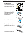
2.3 Memory Support and Installation .......................................................................................25
Memory Support ................................................................................................................25
SO-DIMM Module Population Sequence ..........................................................................25
SO-DIMM Installation ........................................................................................................26
Preface

6
SO-DIMM Removal ...........................................................................................................26
2.4 Rear I/O Ports ....................................................................................................................27
2.5 Front Control Panel ............................................................................................................32
2.6 Connectors .........................................................................................................................36
Power Connections ...........................................................................................................36
Headers .............................................................................................................................38
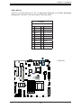
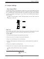
2.7 Jumper Settings .................................................................................................................45
How Jumpers Work ...........................................................................................................45
2.8 LED Indicators ....................................................................................................................52
Chapter 3 Troubleshooting
3.1 Troubleshooting Procedures ..............................................................................................54
Before Power On ..............................................................................................................54
No Power ..........................................................................................................................54
No Video ...........................................................................................................................55
System Boot Failure .......................................................................................................55
Memory Errors ..................................................................................................................55
Losing the System's Setup Conguration .........................................................................56
When the System Becomes Unstable ..............................................................................56
3.2 Technical Support Procedures ...........................................................................................58
3.3 Frequently Asked Questions ..............................................................................................59
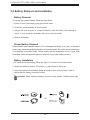
3.4 Battery Removal and Installation .......................................................................................60
Battery Removal ................................................................................................................60
Proper Battery Disposal ....................................................................................................60
Battery Installation .............................................................................................................60
3.5 Returning Merchandise for Service ....................................................................................61
Chapter 4 BIOS
4.1 Introduction .........................................................................................................................62
Starting the Setup Utility ...................................................................................................62
How To Change the Conguration Data ...........................................................................63
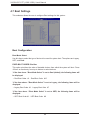
4.2 Main Setup .........................................................................................................................63
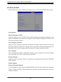
4.3 Advanced Setup Congurations .........................................................................................65
4.4 Event Logs ......................................................................................................................... 88
4.5 IPMI ................................................................................................................................... 90
X11SSH-GF/-GTF (-1585/-1585L) User's Manual

7
4.6 Security ...............................................................................................................................92
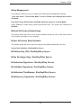
4.7 Boot Settings ......................................................................................................................94
4.8 Save & Exit .........................................................................................................................96
Appendix A BIOS Codes
Appendix B Software Installation
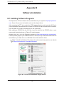
B.1 Installing Software Programs ...........................................................................................100
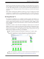
B.2 SuperDoctor
®
5 .................................................................................................................101
Appendix C Standardized Warning Statements
Battery Handling ..............................................................................................................102
Product Disposal .............................................................................................................104
Appendix D UEFI BIOS Recovery

8
X11SSH-GF/-GTF (-1585/-1585L) User's Manual
Main Parts List
Description Part Number Quantity
Supermicro Motherboard X11SSH-GF/-GTF 1
I/O Shield MCP-260-00042-0N 1
57.5CM SATA Flat S-S PBF CBL-0044L 6
X11SSH-GF/-GTF Quick Reference Guide MNL-1924-QRG 1
Chapter 1
Introduction
Congratulations on purchasing your computer motherboard from an industry leader.
Supermicro motherboards are designed to provide you with the highest standards in quality
and performance.
In addition to the motherboard, the following items are included in your shipping package. If
anything listed is damaged or missing, please contact your retailer.
1.1 Checklist
Important Links
For your system to work properly, please follow the links below to download all necessary
drivers/utilities and the user’s manual for your server.
• Supermicro product manuals: http://www.supermicro.com/support/manuals/
• Product drivers and utilities: ftp://ftp.supermicro.com
• Product safety info: http://www.supermicro.com/about/policies/safety_information.cfm
• If you have any questions, please contact our support team at: [email protected]m
This manual may be periodically updated without notice. Please check the Supermicro website
for possible updates to the manual revision level.

9
Chapter 1: Introduction
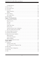
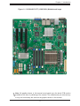
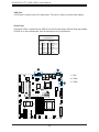
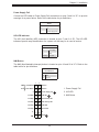
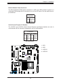
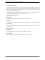
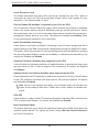
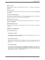
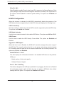
Figure 1-1. X11SSH-GF/-GTF (-1585/1585L) Motherboard Image
Note: All graphics shown in this manual were based upon the latest PCB revision
available at the time of publishing of the manual. The motherboard you received may
or may not look exactly the same as the graphics shown in this manual.

10
X11SSH-GF/-GTF (-1585/-1585L) User's Manual
SAN MAC
DESIGNED IN USA
BIOS LICENSE
+
+
MH10
X11SSH-GF-1585L
REV:1.01
MAC CODE
IPMI CODE
BAR CODE
JSD2
JSD1
JSTBY1
JTPM1
LED2
LEDM1
JPWR2
JPWR1
J23
MH8
MH9
JUIDB1
SP1
JD1
J3
JPI2C1
JL1
JBT1
I-SATA2
I-SATA3
I-SATA5
I-SATA4
I-SATA7
I-SATA6
JF1
LED1
BAT1
JPL1
JVRM2
JWD1
JPME2
JVR1
JPB1
JVRM1
JPG1
J24
JI2C2
JLED1
JBR1
JI2C1
I-SGPIO2
I-SGPIO1
FANA
FAN3
FAN2
FAN1 (CPU FAN)
FAN4
PCH SLOT4 PCI-E 3.0 X4 (IN X8)
Intel®
C236
IPMI_LAN
USB10/11 (3.0)
USB2/3
CPU SLOT5 PCI-E 3.0 X8
USB6/7USB4/5
M.2 CONNECTOR
CPU SLOT6 PCI-E 3.0 X8 (IN X16)
USB12 (3.0)
VGA
LAN2
DIMMB1
LAN1
DIMMB2
DIMMA2
DIMMA1
CPU
USB8/9
(3.0)
USB0/1
NMI
LED
X
1 LED2FAIL LED
RST
JF1
ON
PWRNIC HDDNICPS UIDPWR
COM2
COM1
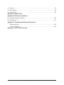
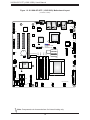
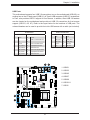
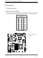
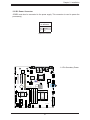
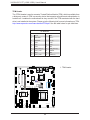
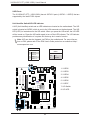
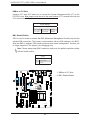
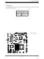
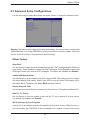
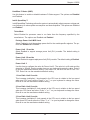
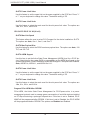
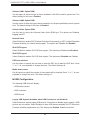
Figure 1-2. X11SSH-GF/-GTF (-1585/1585L) Motherboard Layout
(not drawn to scale)
Note: Components not documented are for internal testing only.

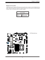
11
Chapter 1: Introduction
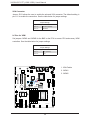
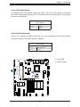
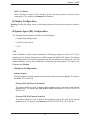
Quick Reference
Notes:
• See Chapter 2 for detailed information on jumpers, I/O ports, and JF1 front panel con-
nections.
• " " indicates the location of Pin 1.
• Jumpers/LED indicators not indicated are used for testing only.
• Use only the correct type of onboard CMOS battery as specied by the manufacturer. Do
not install the onboard battery upside down to avoid possible explosion.
SAN MAC
DESIGNED IN USA
BIOS LICENSE
+
+
MH10
X11SSH-GF-1585L
REV:1.01
MAC CODE
IPMI CODE
BAR CODE
JSD2
JSD1
JSTBY1
JTPM1
LED2
LEDM1
JPWR2
JPWR1
J23
MH8
MH9
JUIDB1
SP1
JD1
J3
JPI2C1
JL1
JBT1
I-SATA2
I-SATA3
I-SATA5
I-SATA4
I-SATA7
I-SATA6
JF1
LED1
BAT1
JPL1
JVRM2
JWD1
JPME2
JVR1
JPB1
JVRM1
JPG1
J24
JI2C2
JLED1
JBR1
JI2C1
I-SGPIO2
I-SGPIO1
FANA
FAN3
FAN2
FAN1 (CPU FAN)
FAN4
PCH SLOT4 PCI-E 3.0 X4 (IN X8)
Intel®
C236
IPMI_LAN
USB10/11 (3.0)
USB2/3
CPU SLOT5 PCI-E 3.0 X8
USB6/7USB4/5
M.2 CONNECTOR
CPU SLOT6 PCI-E 3.0 X8 (IN X16)
USB12 (3.0)
VGA
LAN2
DIMMB1
LAN1
DIMMB2
DIMMA2
DIMMA1
CPU
USB8/9
(3.0)
USB0/1
NMI
LED
X
1 LED2FAIL LED
RST
JF1
ON
PWRNIC HDDNICPS UIDPWR
COM2
COM1
VGA
LAN1
USB8/9 (3.0)
COM1
JUIDB1
JPB1
USB6/7
J24
SLOT4
JLED1
J23
BAT1
JL1
JPME2
I-SATA5
I-SATA4
LED1
FANA
USB4/5
USB2/3
JF1
JPWR1
DIMMA2
FAN3
JVR1
USB0/1
JBR1
JPG1
I-SGPIO2
FAN4
JTPM1
CPU
JVRM1
JSD1
JSD2
I-SATA6
I-SATA3
JI2C2
JWD1
USB10/11 (3.0)
JSTBY1
SAN MAC
DESIGNED IN USA
BIOS LICENSE
+
+
MH10
X11SSH-GF-1585L
REV:1.01
MAC CODE
IPMI CODE
BAR CODE
JSD2
JSD1
JSTBY1
JTPM1
LED2
LEDM1
JPWR2
JPWR1
J23
MH8
MH9
JUIDB1
SP1
JD1
J3
JPI2C1
JL1
JBT1
I-SATA2
I-SATA3
I-SATA5
I-SATA4
I-SATA7
I-SATA6
JF1
LED1
BAT1
JPL1
JVRM2
JWD1
JPME2
JVR1
JPB1
JVRM1
JPG1
J24
JI2C2
JLED1
JBR1
JI2C1
I-SGPIO2
I-SGPIO1
FANA
FAN3
FAN2
FAN1 (CPU FAN)
FAN4
PCH SLOT4 PCI-E 3.0 X4 (IN X8)
Intel®
C236
IPMI_LAN
USB10/11 (3.0)
USB2/3
CPU SLOT5 PCI-E 3.0 X8
USB6/7USB4/5
M.2 CONNECTOR
CPU SLOT6 PCI-E 3.0 X8 (IN X16)
USB12 (3.0)
VGA
LAN2
DIMMB1
LAN1
DIMMB2
DIMMA2
DIMMA1
CPU
USB8/9
(3.0)
USB0/1
NMI
LED
X
1 LED2FAIL LED
RST
JF1
ON
PWRNIC HDDNICPS UIDPWR
COM2
COM1
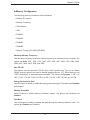
SLOT5
JI2C1
I-SATA2
JBT1
I-SATA7
I-SGPIO1
USB12 (3.0)
FAN2
FAN1 (CPU FAN)
DIMMA1
JPI2C1
DIMMB2
DIMMB1
JPWR2
JPL1
LED2
COM2
SP1
JD1
IPMI_LAN
LAN2
JVRM2
LEDM1
SLOT6

12
X11SSH-GF/-GTF (-1585/-1585L) User's Manual
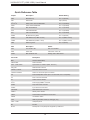
Quick Reference Table
Jumper Description Default Setting
JBR1 BIOS Recovery Pins 1-2 (Normal)
JBT1 CMOS Clear Open (Normal)
JI
2
C1/JI
2
C2 SMB to PCI-E Slots Enable/Disable Pins 2-3 (Disabled)
JLED1 Power LED Enable/Disable Pins 1-2 (Enabled)
JPB1 BMC Enable/Disable Pins 1-2 (Enabled)
JPG1 VGA Enable/Disable Pins 1-2 (Enabled)
JPL1 LAN1/2 Enable/Disable Pins 1-2 (Enabled)
JPME2 ME Manufacturing Mode Pins 1-2 (Normal)
JVRM1 VRM SMB Clock (to BMC or PCH) Pins 1-2 (BMC, Normal)
JVRM2 VRM SMB Data (to BMC or PCH) Pins 1-2 (BMC, Normal)
JWD1 Watch Dog Timer Pins 1-2 (Reset)
LED Description Status
LED1 Unit Identier LED Blue: Unit Identied
LED2 Power LED Solid Green: Power On
LEDM1 BMC Heartbeat LED Blinking Green: BMC Normal
Connector Description
BAT1 Onboard CMOS Battery
COM1/COM2 Serial COM Ports
FAN1 ~ FAN4, FANA System/CPU Fan Headers (FAN1: CPU Fan)
IPMI_LAN Dedicated IPMI LAN Port
I-SATA2 ~ I-SATA7 Intel® PCH SATA 3.0 Ports
I-SGPIO1/I-SGPIO2 Serial Link General Purpose I/O Headers
JD1 Power LED/Speaker Header (Pins 1-3: Power LED, Pins 1-4: Speaker)
JF1 Front Control Panel Header
JL1 Chassis Intrusion Header
JPI
2
C1 Power Supply SMBus I
2
C Header
JPWR1 24-pin ATX Power Connector
JPWR2 4-pin CPU Power Connector
JSD1/JSD2 SATA DOM Power Connectors
JSTBY1 Standby Power Header
JTPM1 Trusted Platform Module/Port 80 Connector
JUIDB1 Unit Identier Switch
JVR1 SMB Programmable Header (for debugging only)
LAN1 ~ LAN2 LAN (RJ45) Ports
M.2 M.2 Slot
SLOT4 PCI-Express 3.0 X4 (IN X8) Slot supported by Intel® PCH

13
Chapter 1: Introduction
Connector Description
SLOT5 PCI-Express 3.0 X8 Slot supported by the CPU
SLOT6 PCI-Express 3.0 X8 (IN X16) Slot supported by the CPU
SP1 Internal Speaker/Buzzer
USB0/1 Back Panel Universal Serial Bus (USB) 2.0 Port
USB2/3, 4/5, 6/7 USB 2.0 Header
USB8/9 Back Panel Universal Serial Bus (USB) 3.0 Port
USB10/11 USB 3.0 Header
USB12 USB 3.0 Type A Header
VGA Back Panel VGA Port

14
X11SSH-GF/-GTF (-1585/-1585L) User's Manual
Note: The table above is continued on the next page.
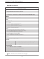
Motherboard Features
CPU
• Single Intel® Xeon® E3-1500 v5 processor in a BGA socket
Memory
• Integrated memory controller supports up to 64GB of unbuffered DDR4 ECC SO-DIMM 2400MHz memory
DIMM Size
• Up to a total of 64GB at 1.2V in four (4) DIMM slots
Chipset
• Intel® PCH C236
Expansion Slots
• One (1) PCI Express 3.0 X4 (IN X8) slot (PCH Slot 4)
• One (1) PCI Express 3.0 X8 Slot (CPU slot 5)
• One (1) PCI Express 3.0 X8 (IN X16) slot (CPU Slot 6)
• One (1) M.2 PCI Express 3.0 x4 connector
Network
• Dual Gbe LAN port (Intel® I350-BT2, X11SSH-GF (-1585/-1585L))
• Dual 10Gbe LAN port (Intel® X550-BT2, X11SSH-GTF (-1585/-1585L))
• One (1) dedicated IPMI LAN located on the rear I/O panel
Baseboard Management Controller (BMC)
• ASpeed 2400 Baseboard Controller (BMC) supports IPMI 2.0
Graphics
• Graphics controller via ASpeed 2400 BMC
I/O Devices
• COM Port • Two (2) COM ports with one (1) in the rear I/O panel and one (1) header
• SATA Ports
• RAID (PCH)
• Six (6) SATA 3.0 ports supported by Intel® PCH (I-SATA2-7)
• RAID 0, 1, 5, and 10
• Video (VGA) Port • One (1) VGA connection on the rear I/O panel
Peripheral Devices
• Two (2) USB 2.0 ports on the rear I/O panel (USB0/1)
• Two (2) USB 3.0 ports on the rear I/O panel (USB8/9)
• Three (3) USB 2.0 internal headers (USB2/3, USB 4/5, USB6/7)
• One (1) USB 3.0 internal header (USB10/11)
• One (1) Type A USB 3.0 header for front access (USB12)
Motherboard Features

15
Chapter 1: Introduction
Motherboard Features
BIOS
• 128Mb SPI AMI BIOS
®
SM Flash UEFI BIOS
• ACPI 3.0 or later, SMBIOS 2.7 or later, PCI F/W 3.0, BIOS rescue hot-key, SPI dual/quad speed support, RTC (Real
Time Clock) wakeup
Power Management
• ACPI power management (S5)
• Power button override mechanism
• Wake-On-LAN
• Power-on mode for AC power recovery
System Health Monitoring
• Onboard voltage monitoring for +1.8V, +3.3V, 3.3V Standby, +5V, +5V Standby, +/-12V, VBAT, HT, Memory, PCH Temp.,
System Temp., Memory Temp.
• CPU switching phase voltage regulator
• CPU thermal trip support
• PECI
Fan Control
• 4-pin fan headers
• Fan speed control
System Management
• IPMI (Intelligent Platform Management Interface) support
• System resource alert via SuperDoctor® 5
• Chassis intrusion detection
• Watch Dog, NMI (Non-maskable interrupt), RoHS (Restriction of Hazardous Substance Directive)
• SPM (Supermicro Power Management), SUM (Supermicro Update Manager) with In-Band and Out-of-Band channels
LED Indicators
• CPU/system overheat
• Power suspend-state
• Fan failure
• UID/remote UID
• HDD activity
• LAN activity
Dimensions
• 9.6" (L) x 9.6" (W) (243.84 mm x 243.84 mm)

16
X11SSH-GF/-GTF (-1585/-1585L) User's Manual
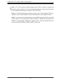
Note 1: The CPU maximum thermal design power (TDP) is subject to chassis and
heatsink cooling restrictions. For proper thermal management, please check the chas-
sis and heatsink specications for proper CPU TDP sizing.
Note 2: For IPMI conguration instructions, please refer to the Embedded IPMI Con-
guration User's Guide available at http://www.supermicro.com/support/manuals/.
Note 3: It is strongly recommended that you change BMC log-in information upon initial
system power-on. The manufacture default username is ADMIN and the password is
ADMIN. For proper BMC conguration, please refer to http://www.supermicro.com/
products/info/les/IPMI/Best_Practices_BMC_Security.pdf

17
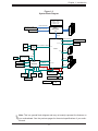
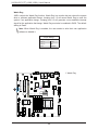
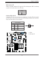
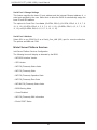
Chapter 1: Introduction
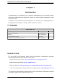
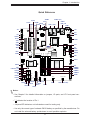
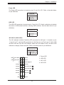
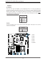
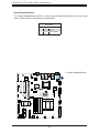
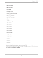
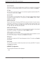
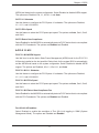
Note: This is a general block diagram and may not exactly represent the features on
your motherboard. See the previous pages for the actual specications of your moth-
erboard.
Figure 1-3.
System Block Diagram
#A-0
#A-1
#B-0
#B-1
#0-7
PCI-E X8 8.0 Gb/S
PCI-E X4 GEN2 / 5.0Gb/S
#5~#8
#5~#8
LAN1
RJ45
2 PHASE for Vcore
1 PHASE for VSA
MUX
IMVP 8 65W
SPI
Xeon
DMI3 x4
DMI3
BGA1440
I350-BT2
X550-BT2
LAN 1
SPI
PHY
RGRMII
Debug Card
FRONT PANEL
SYSTEM POWER
CTRL
FAN SPEED
PCI-E X1 2.5 Gb/S
USB 2.0
#13 USB2.0
#2~#7
USB
#1
#2
#3
#4
#5
PCH
6.0 Gb/S
USB 2.0
LPC
USB
#3
#2
SATA
#7
#6
RTL8211E-VB-CG
#5
#4
RJ45
SPI
Temp Sensor
TPM HEADER
BIOS
SPI
AST2400
BMC
#9/10/11/12
#13
RMII/NCSI
COM1
Connector
COM2
Header
VGA CONN
BMC Boot Flash
DDR3
DDR4-2133
PCIe 3.0 x8 ( in X16)
PCI-E X4 8.0 Gb/S
M.2 SSD
#1
#2
#3
#4
#5
#6
LAN2
RJ45
#7
#8
#10
#11
#9
#12
PCI-E X8 8.0 Gb/S
PCIe 3.0 x8
#8-15
PCI-E X4 8.0 Gb/S
PCIe 3.0 x4 ( in X8)
USB 3.0
#14

18
X11SSH-GF/-GTF (-1585/-1585L) User's Manual
1.2 Processor and Chipset Overview
Built upon the functionality and capability of the Intel® E3-1500 v5 (E3-1585 v5/65W;
E3-1585L v5/45W) series processors (Socket BGA 1440) and the Intel® C236 PCH, the
X11SSH-GF/-GTF (-1585/-1585L) motherboard offers maximum I/O expandability, energy
efciency, and data reliability in a 14-nm process architecture, and is optimized for embedded
storage solutions, networking applications, and cloud-computing platforms.
The Intel® E3-1500 v5 and PCH C236 platform supports the following features:
• ACPI Power Management Logic Support
• Intel® Turbo Boost Technology 2.0 Power Monitoring/Power Control, Turbo Time Parameter
(TAU), and Platform Power Control
• Congurable TDP (cTDP) and Lower-Power Mode
• Adaptive Thermal Management/Monitoring
• PCI-E 3.0, SATA 3.0 with transfer rates of up to 6 Gb/s
• System Management Bus (SMBus) Specication Version 2.0
• Integrated Sensor Hub (ISH)
• Intel® Trusted Execution Technology (Intel® TXT)
• Intel® Rapid Storage Technology
• Intel® Virtualization Technology for Directed I/O (Intel® VT-d)
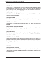
1.3 Special Features
This section describes the health monitoring features of the X11SSH-GF/-GTF motherboard.
The motherboard has an onboard System Hardware Monitor chip that supports system health
monitoring.
Recovery from AC Power Loss
The Basic I/O System (BIOS) provides a setting that determines how the system will respond
when AC power is lost and then restored to the system. You can choose for the system to
remain powered off (in which case you must press the power switch to turn it back on), or
for it to automatically return to the power-on state. See the Advanced BIOS Setup section
for this setting. The default setting is Last State.

19
Chapter 1: Introduction
1.4 System Health Monitoring
This section describes the health monitoring features of the X11SSH-GF/-GTF (-1585/-1585L)
motherboard. The motherboard has an onboard Baseboard Management Controller (BMC)
chip that supports system health monitoring. Once a voltage becomes unstable, a warning is
given or an error message is sent to the screen. The user can adjust the voltage thresholds
to dene the sensitivity of the voltage monitor.
Onboard Voltage Monitors
The onboard voltage monitor will continuously scan crucial voltage levels. Once a voltage
becomes unstable, it will give a warning or send an error message to the screen. Users can
adjust the voltage thresholds to dene the sensitivity of the voltage monitor. Real time readings
of these voltage levels are all displayed in BIOS.
Fan Status Monitor with Firmware Control
The system health monitor embedded in the BMC chip can check the RPM status of the
cooling fans. The CPU and chassis fans are controlled via lPMI.
Environmental Temperature Control
System Health sensors in the BMC monitor the temperatures and voltage settings of onboard
processors and the system in real time via the IPMI interface. Whenever the temperature of
the CPU or the system exceeds a user-dened threshold, system/CPU cooling fans will be
turned on to prevent the CPU or the system from overheating.
Note: To avoid possible system overheating, please be sure to provide adequate air-
ow to your system.
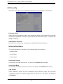
System Resource Alert
This feature is available when used with SuperDoctor 5
®
. SuperDoctor 5 is used to notify the
user of certain system events. For example, you can congure SuperDoctor 5 to provide you
with warnings when the system temperature, CPU temperatures, voltages and fan speeds
go beyond a predened range.

20
X11SSH-GF/-GTF (-1585/-1585L) User's Manual
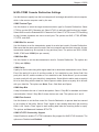
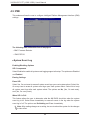
1.5 ACPI Features
ACPI stands for Advanced Conguration and Power Interface. The ACPI specication denes
a exible and abstract hardware interface that provides a standard way to integrate power
management features throughout a computer system including its hardware, operating system
and application software. This enables the system to automatically turn on and off peripherals
such as network cards, hard disk drives and printers.
In addition to enabling operating system-directed power management, ACPI also provides a
generic system event mechanism for Plug and Play and an operating system-independent
interface for conguration control.
1.6 Power Supply
As with all computer products, a stable power source is necessary for proper and reliable
operation. It is even more important for processors that have high CPU clock rates. In areas
where noisy power transmission is present, you may choose to install a line lter to shield
the computer from noise. It is recommended that you also install a power surge protector to
help avoid problems caused by power surges.
1.7 Super I/O
The Super I/O (ASpeed AST2400 chip) includes a data separator, write pre-compensation
circuitry, decode logic, data rate selection, a clock generator, drive interface control logic and
interrupt and DMA logic.
The Super I/O Support 2 sets high-speed, 16550 compatible serial communication ports
(UARTs), which includes support port 80h (programmable address) snoop feature with 128
bytes FIFO mode or DMA mode.
The Super I/O provides functions that comply with ACPI (Advanced Conguration and Power
Interface), which includes support of legacy and ACPI power management through a SMI
or SCI function pin. It also features auto power management to reduce power consumption.
The IRQs, DMAs and I/O space resources of the Super I/O can be exibly adjusted to meet
ISA PnP requirements, which support ACPI and APM (Advanced Power Management).
Page is loading ...
Page is loading ...
Page is loading ...
Page is loading ...
Page is loading ...
Page is loading ...
Page is loading ...
Page is loading ...
Page is loading ...
Page is loading ...
Page is loading ...
Page is loading ...
Page is loading ...
Page is loading ...
Page is loading ...
Page is loading ...
Page is loading ...
Page is loading ...
Page is loading ...
Page is loading ...
Page is loading ...
Page is loading ...
Page is loading ...
Page is loading ...
Page is loading ...
Page is loading ...
Page is loading ...
Page is loading ...
Page is loading ...
Page is loading ...
Page is loading ...
Page is loading ...
Page is loading ...
Page is loading ...
Page is loading ...
Page is loading ...
Page is loading ...
Page is loading ...
Page is loading ...
Page is loading ...
Page is loading ...
Page is loading ...
Page is loading ...
Page is loading ...
Page is loading ...
Page is loading ...
Page is loading ...
Page is loading ...
Page is loading ...
Page is loading ...
Page is loading ...
Page is loading ...
Page is loading ...
Page is loading ...
Page is loading ...
Page is loading ...
Page is loading ...
Page is loading ...
Page is loading ...
Page is loading ...
Page is loading ...
Page is loading ...
Page is loading ...
Page is loading ...
Page is loading ...
Page is loading ...
Page is loading ...
Page is loading ...
Page is loading ...
Page is loading ...
Page is loading ...
Page is loading ...
Page is loading ...
Page is loading ...
Page is loading ...
Page is loading ...
Page is loading ...
Page is loading ...
Page is loading ...
Page is loading ...
Page is loading ...
Page is loading ...
Page is loading ...
Page is loading ...
Page is loading ...
Page is loading ...
Page is loading ...
Page is loading ...
-
 1
1
-
 2
2
-
 3
3
-
 4
4
-
 5
5
-
 6
6
-
 7
7
-
 8
8
-
 9
9
-
 10
10
-
 11
11
-
 12
12
-
 13
13
-
 14
14
-
 15
15
-
 16
16
-
 17
17
-
 18
18
-
 19
19
-
 20
20
-
 21
21
-
 22
22
-
 23
23
-
 24
24
-
 25
25
-
 26
26
-
 27
27
-
 28
28
-
 29
29
-
 30
30
-
 31
31
-
 32
32
-
 33
33
-
 34
34
-
 35
35
-
 36
36
-
 37
37
-
 38
38
-
 39
39
-
 40
40
-
 41
41
-
 42
42
-
 43
43
-
 44
44
-
 45
45
-
 46
46
-
 47
47
-
 48
48
-
 49
49
-
 50
50
-
 51
51
-
 52
52
-
 53
53
-
 54
54
-
 55
55
-
 56
56
-
 57
57
-
 58
58
-
 59
59
-
 60
60
-
 61
61
-
 62
62
-
 63
63
-
 64
64
-
 65
65
-
 66
66
-
 67
67
-
 68
68
-
 69
69
-
 70
70
-
 71
71
-
 72
72
-
 73
73
-
 74
74
-
 75
75
-
 76
76
-
 77
77
-
 78
78
-
 79
79
-
 80
80
-
 81
81
-
 82
82
-
 83
83
-
 84
84
-
 85
85
-
 86
86
-
 87
87
-
 88
88
-
 89
89
-
 90
90
-
 91
91
-
 92
92
-
 93
93
-
 94
94
-
 95
95
-
 96
96
-
 97
97
-
 98
98
-
 99
99
-
 100
100
-
 101
101
-
 102
102
-
 103
103
-
 104
104
-
 105
105
-
 106
106
-
 107
107
-
 108
108


Supermicro X11SSH-GF-1585 User manual
- Category
- Server/workstation motherboards
- Type
- User manual
- This manual is also suitable for
Ask a question and I''ll find the answer in the document
Finding information in a document is now easier with AI
Related papers
-
Supermicro B1SD1-TF User manual
-
Supermicro 5038K-i User manual
-
-
-
Supermicro X11SSH-TF User manual
-
-
-
Supermicro X11SSE-F User manual
-
Supermicro X10SLD-F User manual
-
Other documents
-
 Supero C7B360-CB-M User manual
-
 Supero C7Z170-SQ User manual
-
Shenzhen B W Electronics Development BT022 Wireless Mini Numeric Keypad User manual
-
ASROCK 4X4-7735U-D5 Motherboard User manual
-
Channel Vision CasaTunes User manual
-
protech SP-7755 User manual
-
Grant Instruments CH3-150 Combitherm-2 dry block heating/cooling system User manual
-
BEA PIEZO BUTTON User guide
-
Portwell WEBS-35C3 User manual
-
Leadtek WinFast WS730 User manual

