HP PageWide Enterprise Color MFP 780 Printer series User guide

Type
User guide
1.1
1.2
1
NOTE: The printer MFP model is shown in this procedure. However, the
instructions are correct for all printer models.
Open the left door.
Grasp the green handle on the service fluid container, and then
pull it straight out of the printer.
A7W93-67027
www.hp.com/support/pagewidecolor750
www.hp.com/support/pwcolor765
www.hp.com/support/pagewidecolor772MFP
www.hp.com/support/pagewidecolor777MFP
www.hp.com/support/pwcolor780MFP
www.hp.com/support/pwcolor785MFP
Lea esto primero
Remove the airow assembly
J7Z09-90924.indd 1 8/3/2017 9:31:32 AM
1
2
2
1
2
1
1
2
1.3
1.4
1.5
1.6
Remove one screw (callout 1), and then remove the right cover (callout 2).Remove one screw (callout 1), and then remove the left cover (callout 2).
At the left side of the airflow assembly, disconnect one connector (callout
1) and one flat-flexible cable (FFC) (callout 2).
Loosen two screws (callout 1).
NOTE: These screws are captive and cannot be removed.
J7Z09-90924.indd 2 8/3/2017 9:31:33 AM
3
1.7
1.8
1.9
Grasp the air flow assembly by the outside edges, and rotate the top of the
assembly down and away from the printer.
REINSTALL TIP: It might take considerable force to install the assembly. An
audible click is heard when the assembly is fully engaged. The assembly
cannot be installed if the bottom retainers are not correctly installed.
Slide the airflow assembly straight out of the printer to release it.
CAUTION: Do not damage the FFC or the eject motor on the left side of the
airflow assembly when removing it.
NOTE: Slide the assembly as straight out as possible to avoid binding
interference with the chassis. It might take a considerable pulling force to
release the bottom retainers.
Remove the airow assembly.
NOTE: To prevent damage to the airow star wheels, never place the
assembly on a hard surface (set on a foam pad if available).
J7Z09-90924.indd 3 8/3/2017 9:31:34 AM
2.3
2.4
2.2 2.2
2.1 2.1
Remove four screws..
NOTE: These screws require a #20 TORX driver.
Open the right door, and then use a small flat-blade screwdriver to carefully
push in against the latch to release it.
Open the right- and left-side rear access covers. Rotate the top of the cover away from the printer (callout 1), and
then lift it up to remove it (callout 2).
Push in on the right- (shown) and left-side rear cover latches.
Rotate the top of the cover away from the printer (callout 1), and then lift it up
to remove it (callout 2).
1
2
1
2
4
2
Remove the rear cover (PW765/780/785) Remove the rear cover (PW750/772/777)
J7Z09-90924.indd 4 8/3/2017 9:31:35 AM
1
2
5
3.1
3.2
Loosen two thumbscrews (callout 1) and then lift up on the formatter cage
cover (callout 2) to remove it.
a) For an MFP: Disconnect all of the connectors,
and then pass the wire harnesses and cables through the openings in
the formatter cage.
b) For an SFP: Disconnect all of the connectors,
and then pass the wire harnesses and cables through the openings in
the formatter cage.
Do one of the following:
3
Remove the formatter, formatter cage, and back plate
NOTE: This step is for the PW765/780/785. For all other models, skip this step and go to step 4.
J7Z09-90924.indd 5 8/3/2017 9:31:35 AM
1
1
1
2
6
3.5 3.6
Rotate the bottom edge of the guide away from the printer (callout 1), and
then slightly lift up on the formatter cage while rotating the bottom edge of
the cage away from the printer (callout 2) to release it.
Remove the formatter cage and back plate assembly.
3.3 3.4
Disconnect one connector (callout 1).
REINSTALL TIP: Make sure to reconnect this connector when installing the
formatter and formatter cage. When correctly installed, the line on the FFC
is parallel to the connector body.
Remove four screws.
NOTE: One screw (callout 1) is captive and cannot be completely removed.
J7Z09-90924.indd 6 8/3/2017 9:31:36 AM
1
1
7
4.3 4.4
Release one FFC from the guide (callout 1) Remove two screws (callout 1)
4
Remove the AC controller module (ACCM) ((PW765/780/785) Remove the AC controller module (ACCM) ((PW750/772/777)
1
1
2
2
2
3
4.1
4.2
Release one tab (callout 1), release three pins (callout 2), and then move
the guide out of the way.
Do one of the following:
· MFP models: Disconnect two (callout 1/2), and then release the wire
harnesses from the guide (callout 3).
· SFP models: Disconnect one connector (callout 1), and then release the
wire harness from the guide (callout 3).
1
1
2
3
4.1
4.2
Loosen two screws (callout 1), and then rotate the guide up and away for
the printer to move it out of the way.
NOTE: These screws are captive and cannot be removed.
Do one of the following:
· MFP models: Disconnect five flat-flexible cables (FFCs) (callout 1) and two
connectors (callout 2).
· SFP models: Disconnect two connectors (callout 2) and one FFC (callout 3)
J7Z09-90924.indd 7 8/3/2017 9:31:38 AM
8
4.7 4.8
4.9 4. 10
Carefully pry out on the hinge portion of the lower FFC guide to separate it
from the ACCM, and then move it out of the way.
Disconnect one connector (callout 1), remove four screws (callout 2) on the
sheet-metal plate, and then remove two screws (callout 3) on the ACCM.
REINSTALL TIP: Install the four sheet-metal plate screws (callout 2) after
installing two screws (callout 3)
on the AC control module. Doing so allows the AC module and plate to be
repositioned if the four screw holes in the plate are not completely aligned
with the corresponding threaded holes in the chassis.
Hold the sheet-metal bracket out of the way, and slide the ACCM to the left
and away from the printer.
Remove the ACCM.
4.5 4.6
Push up on the guide to release it, and then move it out of the way.
REINSTALL TIP: There are some tabs on the sheet-metal side of the guide
that install in corresponding holes in the sheet-metal plate. The guide is
flat against the sheet metal when it is correctly installed.
Disconnect three FFCs (callout 1), push in on the FFC just below the ferrite
(callout 2) to release a tab, and then slide the ferrite down and out of the
holder (callout 3).
1
2
3
1
2
3
J7Z09-90924.indd 8 8/3/2017 9:31:39 AM
9
5.3
5.1
5
5.2
From the printer control panel, do the following:
a. Scroll to, and then select the Support Tools button.
b. Select the Service button to display the Sign In screen.
c. Use the keypad to enter the following printer service access
personal identification number (PIN):
09078017 (780/785 models)
09076517 (765 models)
d. Select Sign In to enter the Service menu.
NOTE: The printer must restart to enter the Service menu.
This can take up to 2 minutes.
e. Open the following menus:
Advanced Service
Component Tests
f. Select the Airflow Systems Motors item, and then select the
two different fans and then the Start button.
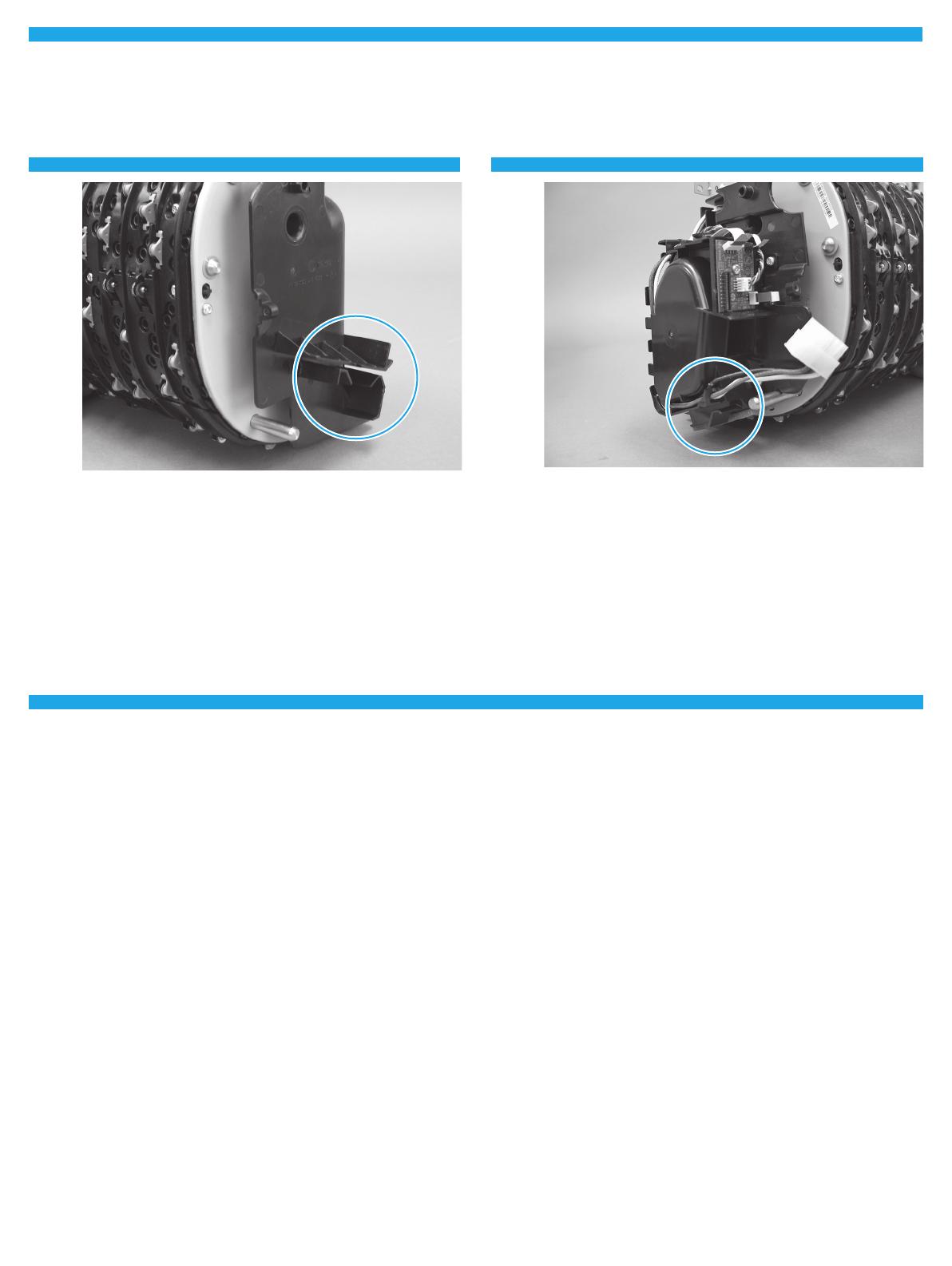
Take note of the mounting rail on the right side of the airow
assembly. This rail slides over a corresponding mounting bracket
on the right side of the printer chassis.
CAUTION: To prevent damage to the assembly or the printer, the
rail must be correctly aligned and installed on the bracket.
Reverse the removal steps to install the assembly. Also use the
following special installation instructions.
SPECIAL INSTALLATION INSTRUCTIONS: Airow assembly
Take note of the mounting rail on the left side of the airow
assembly. This rail slides over a corresponding mounting bracket
on the left side of the printer chassis.
CAUTION: To prevent damage to the assembly or the printer, the
rail must be correctly aligned and installed on the bracket.
NOTE: Continue to reverse the removal steps to nish installing
the assembly.
PW765/780/785 PW750/772/777
From the printer control panel, do the following:
a. Scroll to, and then touch the Support Tools button.
b. Touch the Service button.
c. Touch the Enter Access Code button.
d. Use the keypad to enter the following printer service access
personal identification number (PIN), and then touch the
Done button:
05075017
NOTE: It might take up to 2 minutes to enter the Service menu.
e. Touch the Subsystems button, and then touch the Printing
System button.
f. Touch the Airflow Subsystems button.
g. Select from the following airflow system tests, and then
touch the OK button to perform the test:
Subsystem information
Airflow Assembly Test
Airflow Assembly Fan
Aerosol Fan
J7Z09-90924.indd 9 8/3/2017 9:31:40 AM
10
J7Z09-90924.indd 10 8/3/2017 9:31:40 AM
11
J7Z09-90924.indd 11 8/3/2017 9:31:40 AM
© Copyright 2017 HP Development Company, L.P.
www.hp.com
J7Z09-90924.indd 12 8/3/2017 9:31:40 AM
J7Z09-90924
*J7Z09-90924*
*J7Z09-90924*
  • Page 1 1
  • Page 2 2
  • Page 3 3
  • Page 4 4
  • Page 5 5
  • Page 6 6
  • Page 7 7
  • Page 8 8
  • Page 9 9
  • Page 10 10
  • Page 11 11
  • Page 12 12

HP PageWide Enterprise Color MFP 780 Printer series User guide

Type
User guide

Ask a question and I''ll find the answer in the document

Finding information in a document is now easier with AI