Page is loading ...

www.rkiinstruments.com
GX-3R Pro
Operator’s Manual
Part Number: 71-0478
Revision: P11
Released: 6/3/20

GX-3R Pro Operator’s Manual
WARNING
Read and understand this instruction manual before operating instrument.
Improper use of the gas monitor could result in bodily harm or death.
Maintenance of the gas monitor is essential for proper operation and correct
readings.
Bump test the instrument before each day’s use with a known concentration of
each target gas. A bump test can be done in User Mode’s BUMP TEST item or
by applying gas in Measuring Mode. The instrument does not need to be
calibrated unless it does not pass the User Mode bump test or does not respond
appropriately, as defined by the user, in Measuring Mode. For more
information about bump test and calibration requirements, see IEC 60079-29-
2.

GX-3R Pro Operator’s Manual
Table of Contents
Chapter 1: Introduction . . . . . . . . . . . . . . . . . . . . . . . . . . . . . . . . . . . . . . . . . . . . 7
Overview . . . . . . . . . . . . . . . . . . . . . . . . . . . . . . . . . . . . . . . . . . . . . . . . . . . . . . . . . . . . . . 7
About the GX-3R Pro . . . . . . . . . . . . . . . . . . . . . . . . . . . . . . . . . . . . . . . . . . . . . . . . . . . . 7
Specifications . . . . . . . . . . . . . . . . . . . . . . . . . . . . . . . . . . . . . . . . . . . . . . . . . . . . . . . . . . . 8
About this Manual . . . . . . . . . . . . . . . . . . . . . . . . . . . . . . . . . . . . . . . . . . . . . . . . . . . . . . 11
Chapter 2: Description . . . . . . . . . . . . . . . . . . . . . . . . . . . . . . . . . . . . . . . . . . . . 12
Overview . . . . . . . . . . . . . . . . . . . . . . . . . . . . . . . . . . . . . . . . . . . . . . . . . . . . . . . . . . . . . 12
Instrument Description . . . . . . . . . . . . . . . . . . . . . . . . . . . . . . . . . . . . . . . . . . . . . . . . . . 12
Case . . . . . . . . . . . . . . . . . . . . . . . . . . . . . . . . . . . . . . . . . . . . . . . . . . . . . . . . . . . 12
LCD . . . . . . . . . . . . . . . . . . . . . . . . . . . . . . . . . . . . . . . . . . . . . . . . . . . . . . . . . . . 12
Control Buttons . . . . . . . . . . . . . . . . . . . . . . . . . . . . . . . . . . . . . . . . . . . . . . . . . . 13
Alarm LEDs . . . . . . . . . . . . . . . . . . . . . . . . . . . . . . . . . . . . . . . . . . . . . . . . . . . . . 13
Buzzer . . . . . . . . . . . . . . . . . . . . . . . . . . . . . . . . . . . . . . . . . . . . . . . . . . . . . . . . . . 13
Vibrator . . . . . . . . . . . . . . . . . . . . . . . . . . . . . . . . . . . . . . . . . . . . . . . . . . . . . . . . . 13
Sensors . . . . . . . . . . . . . . . . . . . . . . . . . . . . . . . . . . . . . . . . . . . . . . . . . . . . . . . . . 13
Filters . . . . . . . . . . . . . . . . . . . . . . . . . . . . . . . . . . . . . . . . . . . . . . . . . . . . . . . . . . 14
Infrared Communications Port . . . . . . . . . . . . . . . . . . . . . . . . . . . . . . . . . . . . . . . 15
Charging Socket . . . . . . . . . . . . . . . . . . . . . . . . . . . . . . . . . . . . . . . . . . . . . . . . . . 15
Included Accessories . . . . . . . . . . . . . . . . . . . . . . . . . . . . . . . . . . . . . . . . . . . . . . . . . . . . 16
Alligator Clip . . . . . . . . . . . . . . . . . . . . . . . . . . . . . . . . . . . . . . . . . . . . . . . . . . . . 16
Rubber Boot . . . . . . . . . . . . . . . . . . . . . . . . . . . . . . . . . . . . . . . . . . . . . . . . . . . . . 16
Wrist Strap . . . . . . . . . . . . . . . . . . . . . . . . . . . . . . . . . . . . . . . . . . . . . . . . . . . . . . 16
Single-Unit AC Charger . . . . . . . . . . . . . . . . . . . . . . . . . . . . . . . . . . . . . . . . . . . . 17
Calibration Cup . . . . . . . . . . . . . . . . . . . . . . . . . . . . . . . . . . . . . . . . . . . . . . . . . . 17
Other Accessories . . . . . . . . . . . . . . . . . . . . . . . . . . . . . . . . . . . . . . . . . . . . . . . . . . . . . . 17
12 VDC Charger . . . . . . . . . . . . . . . . . . . . . . . . . . . . . . . . . . . . . . . . . . . . . . . . . . 17
Multi-Unit AC Charger . . . . . . . . . . . . . . . . . . . . . . . . . . . . . . . . . . . . . . . . . . . . . 17
Belt Clip . . . . . . . . . . . . . . . . . . . . . . . . . . . . . . . . . . . . . . . . . . . . . . . . . . . . . . . . 18
SDM-3R. . . . . . . . . . . . . . . . . . . . . . . . . . . . . . . . . . . . . . . . . . . . . . . . . . . . . . . . . 18
RP-3R . . . . . . . . . . . . . . . . . . . . . . . . . . . . . . . . . . . . . . . . . . . . . . . . . . . . . . . . . . 18
Aspirator Adapter . . . . . . . . . . . . . . . . . . . . . . . . . . . . . . . . . . . . . . . . . . . . . . . . . 18
IrDA Cable . . . . . . . . . . . . . . . . . . . . . . . . . . . . . . . . . . . . . . . . . . . . . . . . . . . . . . 18
Chapter 3: Measuring Mode . . . . . . . . . . . . . . . . . . . . . . . . . . . . . . . . . . . . . . . 19
Overview . . . . . . . . . . . . . . . . . . . . . . . . . . . . . . . . . . . . . . . . . . . . . . . . . . . . . . . . . . . . . 19
Start Up . . . . . . . . . . . . . . . . . . . . . . . . . . . . . . . . . . . . . . . . . . . . . . . . . . . . . . . . . . . . . . 19
Turning On the GX-3R Pro . . . . . . . . . . . . . . . . . . . . . . . . . . . . . . . . . . . . . . . . . 19
Performing a Demand Zero . . . . . . . . . . . . . . . . . . . . . . . . . . . . . . . . . . . . . . . . . 24
Turning Off the GX-3R Pro . . . . . . . . . . . . . . . . . . . . . . . . . . . . . . . . . . . . . . . . . 24
Measuring Mode Operation . . . . . . . . . . . . . . . . . . . . . . . . . . . . . . . . . . . . . . . . . . . . . . . 25
Monitoring an Area . . . . . . . . . . . . . . . . . . . . . . . . . . . . . . . . . . . . . . . . . . . . . . . 25
Combustible Gas Detection . . . . . . . . . . . . . . . . . . . . . . . . . . . . . . . . . . . . . . . . . 26
Oxygen-Enriched Atmospheres. . . . . . . . . . . . . . . . . . . . . . . . . . . . . . . . . . . . . . . 27
H2-Compensated CO Detection . . . . . . . . . . . . . . . . . . . . . . . . . . . . . . . . . . . . . . 27

GX-3R Pro Operator’s Manual
Interference Information . . . . . . . . . . . . . . . . . . . . . . . . . . . . . . . . . . . . . . . . . . . . 27
CO2 Detection . . . . . . . . . . . . . . . . . . . . . . . . . . . . . . . . . . . . . . . . . . . . . . . . . . . 28
Aspirator Adapter Sampling . . . . . . . . . . . . . . . . . . . . . . . . . . . . . . . . . . . . . . . . . 28
Alarms . . . . . . . . . . . . . . . . . . . . . . . . . . . . . . . . . . . . . . . . . . . . . . . . . . . . . . . . . . . . . . . 29
Alarm Indications . . . . . . . . . . . . . . . . . . . . . . . . . . . . . . . . . . . . . . . . . . . . . . . . . 29
Responding to Alarms . . . . . . . . . . . . . . . . . . . . . . . . . . . . . . . . . . . . . . . . . . . . . 32
Data Logging . . . . . . . . . . . . . . . . . . . . . . . . . . . . . . . . . . . . . . . . . . . . . . . . . . . . . . . . . . 35
Chapter 4: Display Mode . . . . . . . . . . . . . . . . . . . . . . . . . . . . . . . . . . . . . . . . . . 36
Tips for Using Display Mode . . . . . . . . . . . . . . . . . . . . . . . . . . . . . . . . . . . . . . . . . . . . . . 37
Peak Screen (PEAK). . . . . . . . . . . . . . . . . . . . . . . . . . . . . . . . . . . . . . . . . . . . . . . . . . . . . 38
STEL Screen (STEL) . . . . . . . . . . . . . . . . . . . . . . . . . . . . . . . . . . . . . . . . . . . . . . . . . . . . 38
TWA Screen (TWA) . . . . . . . . . . . . . . . . . . . . . . . . . . . . . . . . . . . . . . . . . . . . . . . . . . . . . 39
Combustible Sensor Target Gas Conversion (HC GAS LIST). . . . . . . . . . . . . . . . . . . . . 39
User ID Screen (USER ID). . . . . . . . . . . . . . . . . . . . . . . . . . . . . . . . . . . . . . . . . . . . . . . . 41
Station ID Screen (STATION ID). . . . . . . . . . . . . . . . . . . . . . . . . . . . . . . . . . . . . . . . . . . 42
Last Successful Calibration Date (CAL DATA) . . . . . . . . . . . . . . . . . . . . . . . . . . . . . . . . 42
Last Successful Bump Test Date (BUMP DATA) . . . . . . . . . . . . . . . . . . . . . . . . . . . . . . 43
Date, Time, and Temperature Screen (DATE) . . . . . . . . . . . . . . . . . . . . . . . . . . . . . . . . . 44
Alarm Points Screen (ALARM POINTS) . . . . . . . . . . . . . . . . . . . . . . . . . . . . . . . . . . . . 45
Screen Inversion On/Off (INVERT SELECT) . . . . . . . . . . . . . . . . . . . . . . . . . . . . . . . . . 46
LCD Color Scheme (LCD BACKGROUND) . . . . . . . . . . . . . . . . . . . . . . . . . . . . . . . . . 46
Turning Bluetooth On/Off (BLUETOOTH). . . . . . . . . . . . . . . . . . . . . . . . . . . . . . . . . . . 47
Adjusting the Buzzer Volume (BUZZER VOLUME) . . . . . . . . . . . . . . . . . . . . . . . . . . . 47
Changing Instrument Language Back to English (LANGUAGE) . . . . . . . . . . . . . . . . . . 48
Chapter 5: User Mode and Calibration. . . . . . . . . . . . . . . . . . . . . . . . . . . . . . . 49
Overview. . . . . . . . . . . . . . . . . . . . . . . . . . . . . . . . . . . . . . . . . . . . . . . . . . . . . . . . . . . . . . 49
Entering User Mode . . . . . . . . . . . . . . . . . . . . . . . . . . . . . . . . . . . . . . . . . . . . . . . . . . . . . 53
Tips for Using User Mode . . . . . . . . . . . . . . . . . . . . . . . . . . . . . . . . . . . . . . . . . . . . . . . . 54
Performing a Bump Test (BUMP TEST) . . . . . . . . . . . . . . . . . . . . . . . . . . . . . . . . . . . . . 55
Performing a Calibration (GAS CAL) . . . . . . . . . . . . . . . . . . . . . . . . . . . . . . . . . . . . . . . 61
Setting Calibration Parameters (CAL SETTING) . . . . . . . . . . . . . . . . . . . . . . . . . . . . . . 74
Setting Bump Test Parameters (BUMP SETTING) . . . . . . . . . . . . . . . . . . . . . . . . . . . . . 76
Adjusting Man Down and Panic Settings (MAN DOWN). . . . . . . . . . . . . . . . . . . . . . . . 81
Alarm Settings (ALARM SETTING). . . . . . . . . . . . . . . . . . . . . . . . . . . . . . . . . . . . . . . . 83
Updating the Lunch Break Setting (LUNCH BREAK) . . . . . . . . . . . . . . . . . . . . . . . . . . 86
Setting the Confirmation Beep and Non-Compliance Indicator (CONFIRMATION). . . 87
Auto Backlight in Low Light (AUTO BACKLIGHT). . . . . . . . . . . . . . . . . . . . . . . . . . . 89
Updating the Backlight Time (BACKLIGHT TIME). . . . . . . . . . . . . . . . . . . . . . . . . . . . 89
Turning the Key Tone On/Off (KEY TONE) . . . . . . . . . . . . . . . . . . . . . . . . . . . . . . . . . . 90
Display Mode Items (D MODE SETTING). . . . . . . . . . . . . . . . . . . . . . . . . . . . . . . . . . . 90
Reading Units for IR Sensor (IR UNIT SELECT) . . . . . . . . . . . . . . . . . . . . . . . . . . . . . . 91
CO2 Fresh Air Adjustment On/Off (CO2 AIR SETTING) . . . . . . . . . . . . . . . . . . . . . . . 92
Setting the Date/Time (DATE) . . . . . . . . . . . . . . . . . . . . . . . . . . . . . . . . . . . . . . . . . . . . . 92
Setting the Date Format (DATE FORMAT) . . . . . . . . . . . . . . . . . . . . . . . . . . . . . . . . . . . 93
Changing the Instrument Language (LANGUAGE) . . . . . . . . . . . . . . . . . . . . . . . . . . . . 93
Turning the Password On/Off (USER PASSWORD). . . . . . . . . . . . . . . . . . . . . . . . . . . . 94

GX-3R Pro Operator’s Manual
Viewing the ROM/SUM (ROM/SUM). . . . . . . . . . . . . . . . . . . . . . . . . . . . . . . . . . . . . . . 94
Viewing the Radio Standards (RADIO STANDARD) . . . . . . . . . . . . . . . . . . . . . . . . . . . 95
Returning to Measuring Mode (START MEASURE) . . . . . . . . . . . . . . . . . . . . . . . . . . . 96
Chapter 6: Maintenance . . . . . . . . . . . . . . . . . . . . . . . . . . . . . . . . . . . . . . . . . . 97
Overview . . . . . . . . . . . . . . . . . . . . . . . . . . . . . . . . . . . . . . . . . . . . . . . . . . . . . . . . . . . . . 97
Troubleshooting . . . . . . . . . . . . . . . . . . . . . . . . . . . . . . . . . . . . . . . . . . . . . . . . . . . . . . . .97
Instrument Cleaning . . . . . . . . . . . . . . . . . . . . . . . . . . . . . . . . . . . . . . . . . . . . . . . . . . . . . 98
Replacing the Batteries (Alkaline Version). . . . . . . . . . . . . . . . . . . . . . . . . . . . . . . . . . . . 98
Recharging the Batteries (Li-ion Version) . . . . . . . . . . . . . . . . . . . . . . . . . . . . . . . . . . . . 98
Replacing the Buzzer Cover . . . . . . . . . . . . . . . . . . . . . . . . . . . . . . . . . . . . . . . . . . . . . . 101
Replacing the Sensor Filters . . . . . . . . . . . . . . . . . . . . . . . . . . . . . . . . . . . . . . . . . . . . . . 101
Replacing the Hydrophobic Dust Filter . . . . . . . . . . . . . . . . . . . . . . . . . . . . . . . . . . . . . 103
Replacing a Sensor . . . . . . . . . . . . . . . . . . . . . . . . . . . . . . . . . . . . . . . . . . . . . . . . . . . . . 104
Chapter 7: Storage and Disposal . . . . . . . . . . . . . . . . . . . . . . . . . . . . . . . . . . . 106
Chapter 8: General Parts List . . . . . . . . . . . . . . . . . . . . . . . . . . . . . . . . . . . . . 107
Appendix A: RK Link Phone App . . . . . . . . . . . . . . . . . . . . . . . . . . . . . . . . . . 110
Installing the App . . . . . . . . . . . . . . . . . . . . . . . . . . . . . . . . . . . . . . . . . . . . . . . . . . . . . . 110
Important Setup Notes . . . . . . . . . . . . . . . . . . . . . . . . . . . . . . . . . . . . . . . . . . . . . . . . . . 110
Pairing a GX-3R Pro. . . . . . . . . . . . . . . . . . . . . . . . . . . . . . . . . . . . . . . . . . . . . . . . . . . . 110
Searching for a Paired GX-3R Pro . . . . . . . . . . . . . . . . . . . . . . . . . . . . . . . . . . . . . . . . . 113
Disconnecting a Paired GX-3R Pro . . . . . . . . . . . . . . . . . . . . . . . . . . . . . . . . . . . . . . . . 114
Adjusting App Notification Settings. . . . . . . . . . . . . . . . . . . . . . . . . . . . . . . . . . . . . . . . 115
Defining Owner Information . . . . . . . . . . . . . . . . . . . . . . . . . . . . . . . . . . . . . . . . . . . . . 117
Setting Up Email/Text Alerts . . . . . . . . . . . . . . . . . . . . . . . . . . . . . . . . . . . . . . . . . . . . . 119
Changing GX-3R Pro Parameters. . . . . . . . . . . . . . . . . . . . . . . . . . . . . . . . . . . . . . . . . . 129
Alarm Settings. . . . . . . . . . . . . . . . . . . . . . . . . . . . . . . . . . . . . . . . . . . . . . . . . . . 130
Calibration and Bump Settings. . . . . . . . . . . . . . . . . . . . . . . . . . . . . . . . . . . . . . 132
Backlight Setting . . . . . . . . . . . . . . . . . . . . . . . . . . . . . . . . . . . . . . . . . . . . . . . . . 133
Logger Data Settings . . . . . . . . . . . . . . . . . . . . . . . . . . . . . . . . . . . . . . . . . . . . . 134
Viewing Serial Number, IDs, and Bump/Cal Information . . . . . . . . . . . . . . . . . . . . . . . 135
Viewing App Version Info . . . . . . . . . . . . . . . . . . . . . . . . . . . . . . . . . . . . . . . . . . . . . . . 138
Appendix B: Maintenance Mode . . . . . . . . . . . . . . . . . . . . . . . . . . . . . . . . . . 140
Overview . . . . . . . . . . . . . . . . . . . . . . . . . . . . . . . . . . . . . . . . . . . . . . . . . . . . . . . . . . . . 140
Entering Maintenance Mode . . . . . . . . . . . . . . . . . . . . . . . . . . . . . . . . . . . . . . . . . . . . . 142
Tips for Using Maintenance Mode . . . . . . . . . . . . . . . . . . . . . . . . . . . . . . . . . . . . . . . . . 143
Performing a Calibration (GAS CAL) . . . . . . . . . . . . . . . . . . . . . . . . . . . . . . . . . . . . . . 143
Performing a Gas Test (GAS TEST). . . . . . . . . . . . . . . . . . . . . . . . . . . . . . . . . . . . . . . . 143
Sensor/Battery Replacement Date (SENSOR DATE) . . . . . . . . . . . . . . . . . . . . . . . . . . 145
Performing a Bump Test (BUMP TEST) . . . . . . . . . . . . . . . . . . . . . . . . . . . . . . . . . . . . 146
Setting Alarms to Latching or Self-Resetting (LATCHING) . . . . . . . . . . . . . . . . . . . . . 147
Turning Demand Zero On/Off (DEMAND ZERO) . . . . . . . . . . . . . . . . . . . . . . . . . . . . 147
Turning Auto Zero On/Off (AUTO ZERO) . . . . . . . . . . . . . . . . . . . . . . . . . . . . . . . . . . 148
Turning ID Display Function On/Off (ID DISPLAY) . . . . . . . . . . . . . . . . . . . . . . . . . . 148

GX-3R Pro Operator’s Manual
Turning Zero Suppression On/Off (ZERO SUPPRESS) . . . . . . . . . . . . . . . . . . . . . . . . 149
Turning Zero Follower On/Off (ZERO FOLLOWER) . . . . . . . . . . . . . . . . . . . . . . . . . 149
User Mode Zero Suppression (DISP ZERO SUP) . . . . . . . . . . . . . . . . . . . . . . . . . . . . . 149
User Mode Zero Follower (DISP ZERO FLWR) . . . . . . . . . . . . . . . . . . . . . . . . . . . . . . 149
Setting the Date/Time (DATE) . . . . . . . . . . . . . . . . . . . . . . . . . . . . . . . . . . . . . . . . . . . . 149
Setting the Date Format (DATE FORMAT) . . . . . . . . . . . . . . . . . . . . . . . . . . . . . . . . . . 150
Setting the Instrument Language (LANGUAGE) . . . . . . . . . . . . . . . . . . . . . . . . . . . . . 150
Turning the Password On/Off (MAINT PASSWORD) . . . . . . . . . . . . . . . . . . . . . . . . . 151
Viewing the ROM/SUM (ROM/SUM). . . . . . . . . . . . . . . . . . . . . . . . . . . . . . . . . . . . . . 152
Adjusting the LCD’s Contrast (LCD CONTRAST). . . . . . . . . . . . . . . . . . . . . . . . . . . . 153
Performing a Default (M.DEFAULT). . . . . . . . . . . . . . . . . . . . . . . . . . . . . . . . . . . . . . . 153
Exiting Maintenance Mode (START MEASURE). . . . . . . . . . . . . . . . . . . . . . . . . . . . . 154
Appendix C: Gas Select Mode . . . . . . . . . . . . . . . . . . . . . . . . . . . . . . . . . . . . . 155
Overview. . . . . . . . . . . . . . . . . . . . . . . . . . . . . . . . . . . . . . . . . . . . . . . . . . . . . . . . . . . . . 155
Entering Gas Select Mode . . . . . . . . . . . . . . . . . . . . . . . . . . . . . . . . . . . . . . . . . . . . . . . 155
Tips for Using Gas Select Mode . . . . . . . . . . . . . . . . . . . . . . . . . . . . . . . . . . . . . . . . . . . 156
Changing the Gas Combination (GAS COMBO). . . . . . . . . . . . . . . . . . . . . . . . . . . . . . 157
Saving the Alarm Points (SAVE ALARM-P) . . . . . . . . . . . . . . . . . . . . . . . . . . . . . . . . . 159
Turning the Calibration Max Span On/Off (DISP MAX SPAN) . . . . . . . . . . . . . . . . . . 159
Stealth and Vibrator Settings (STEALTH) . . . . . . . . . . . . . . . . . . . . . . . . . . . . . . . . . . . 160
LEL Definition (CHANGE LEL) . . . . . . . . . . . . . . . . . . . . . . . . . . . . . . . . . . . . . . . . . . 161
Exiting Gas Select Mode (START MEASURE). . . . . . . . . . . . . . . . . . . . . . . . . . . . . . . 162
Appendix D: Interference Information . . . . . . . . . . . . . . . . . . . . . . . . . . . . . . 163
ESR-A13D-SO2, SO
2
Detection . . . . . . . . . . . . . . . . . . . . . . . . . . . . . . . . . . . . . . . . . . 163
ESR-A13i-H2S, H
2
S Detection . . . . . . . . . . . . . . . . . . . . . . . . . . . . . . . . . . . . . . . . . . . 165
ESR-A13P-CO, CO Detection . . . . . . . . . . . . . . . . . . . . . . . . . . . . . . . . . . . . . . . . . . . . 167
ESR-A1CP-COH, H
2
-Compensated CO Detection . . . . . . . . . . . . . . . . . . . . . . . . . . . . 169
ESR-A1DP-COHS, CO Detection . . . . . . . . . . . . . . . . . . . . . . . . . . . . . . . . . . . . . . . . . 171
ESR-A1DP-COHS, H
2
S Detection. . . . . . . . . . . . . . . . . . . . . . . . . . . . . . . . . . . . . . . . . 173
WARNING: Understand manual before operating. Substitution of components may
impair intrinsic safety. To prevent ignition of a hazardous atmosphere,
batteries must only be changed or charged in an area known to be
nonhazardous.

GX-3R Pro Operator’s Manual Chapter 1: Introduction • 7
Chapter 1: Introduction
Overview
This chapter briefly describes the GX-3R Pro gas monitor. This chapter also describes the
GX-3R Pro Operator’s Manual (this document). Table 1 at the end of this chapter lists the
specifications for the GX-3R Pro.
About the GX-3R Pro
Using an advanced detection system consisting of up to four gas sensors, the GX-3R Pro
personal five-gas monitor detects the presence of combustible gas, oxygen (O
2
), carbon
monoxide (CO), hydrogen sulfide (H
2
S), and CO
2
or a super toxic gas simultaneously. The
GX-3R Pro’s compact size and easy-to-use design make it ideally suited for a wide range of
applications, including sewage treatment plants, utility manholes, tunnels, hazardous waste
sites, power stations, petrochemical refineries, mines, paper mills, drilling rigs, and fire
fighting stations. The GX-3R Pro offers a full range of features, including:
• Simultaneous monitoring of one to five gases
• Liquid crystal display (LCD) for complete and understandable information at a glance
• Ultrabright alarm LEDs
• Distinctive audible/vibrating alarms for dangerous gas conditions and audible alarms for
unit malfunction
• Microprocessor control for reliability, ease of use, and advanced capabilities
• Data logging functions
• Alarm trend data
• STEL, TWA, and over range alarms
• Peak readings
• Built-in time function
• Lunch break feature
• CSA “C/US” classified as intrinsically safe (see Table 4 on page9)
WARNING: The Model GX-3R Pro detects oxygen deficiency, elevated levels of oxygen,
combustible gases, carbon monoxide, and hydrogen sulfide, all of which
can be dangerous or life threatening. When using the GX-3R Pro, you must
follow the instructions and warnings in this manual to assure proper and
safe operation of the unit and to minimize the risk of personal injury. Be
sure to maintain and periodically calibrate the GX-3R Pro as described in
this manual.

8 • Chapter 1: Introduction GX-3R Pro Operator’s Manual
Specifications
Table 1: Standard Sensor Specifications
Table 2: IR Sensor Specifications
Combustible Gas,
Methane (CH
4
)
Calibration Standard*
Oxygen (O
2
)Hydrogen
Sulfide (H
2
S)
Carbon
Monoxide (CO)
Detection Range 0 - 100% LEL 0 - 25.0% volume 0 - 100.0 ppm 0 - 500 ppm
Service Range n/a 25.1 - 40.0% volume 100.1 - 200.0 ppm 501 - 2,000 ppm
Reading
Increment
1% LEL 0.1% volume 0.1 ppm 1 ppm
Warning
Factory Setting
10% LEL 19.5% volume,
decreasing
5.0 ppm 25 ppm
Alarm
Factory Setting
25% LEL 18.0% volume,
decreasing
30.0 ppm 50 ppm
Alarm H
Factory Setting
50% LEL 23.5% volume,
increasing
100.0 ppm 1200 ppm
STEL Alarm n/a n/a 5.0 ppm 200 ppm
TWA Alarm n/a n/a 1.0 ppm 25 ppm
* The GX-3R Pro is also available set up for general hydrocarbons and calibrated to a combustible gas other than methane, such
as isobutane. Consult RKI Instruments, Inc. for further information.
Carbon Dioxide (CO
2
)
Detection Range 0 - 5.00% volume 0 - 10,000 ppm
Service Range 5.01 - 10.00% volume n/a
Reading
Increment
0.01% volume 20 ppm
Warning
Factory Setting
0.50% volume 5,000 ppm
Alarm
Factory Setting
3.00% volume 5,000 ppm
Alarm H
Factory Setting
3.00% volume 5,000 ppm
STEL Alarm 3.00% volume n/a
TWA Alarm 0.50% volume 5,000 ppm

GX-3R Pro Operator’s Manual Chapter 1: Introduction • 9
Table 3: EC Sensor Specifications
Table 4: GX-3R Pro Specifications
Sulfur Dioxide (SO
2
)
Detection Range
and Service Range
0 - 100.00 ppm (parts
per million)
Reading
Increment
0.05 ppm
Warning
Factory Setting
2.00 ppm
Alarm
Factory Setting
5.00 ppm
Alarm H
Factory Setting
100.00 ppm
STEL Alarm 5.00 ppm
TWA Alarm 2.00 ppm
Sampling
Method
Diffusion
Response Time T90 within 30 seconds
Display Graphics LCD Display
Environmental
Conditions
• 3000 meter maximum altitude
• Operating pressure: 70 - 120 kPa (70 - 110 kPa for explosion proof)
• Pollution degree 2
•IP 66/68
Operating
Temperature &
Humidity
Continuous environment: -20°C to 50
°
C/Below 90% RH
Temporary environment (up to 15 minutes): -40°C to 60
°
C/Below 95% RH
Indication
Accuracy for
Detection
Range
Combustible Gas, Catalytic Type Sensor
• Continuous environment (-20°C to 50
°
C): ± 5% of reading or ± 2% LEL (whichever is greater)
• Temporary environment (-40°C to -21°C and 51°C to 60°C): ± 10% LEL
Oxygen
± 0.5% O
2
Hydrogen Sulfide
± 5% of reading or ± 2 ppm H
2
S (whichever is greater)
Carbon Monoxide
± 5% of reading or ± 5 ppm CO (whichever is greater)
Carbon Dioxide (IR)
± 5% of reading or ± 2% of full scale (whichever is greater)
Sulfur Dioxide (EC)
± 10% of reading or ± 5% of full scale (whichever is greater)

10 • Chapter 1: Introduction GX-3R Pro Operator’s Manual
Indication
Accuracy for
Service
Range
Oxygen
± 3.0% O
2
Hydrogen Sulfide, Carbon Monoxide, and Carbon Dioxide
± 20% of reading
Safety/
Regulatory
• ATEX: Certificate Number: DEKRA 17ATEX0103 X
II1G Ex da ia IIC T4 Ga/IM1 Ex da ia I Ma (with NCR-6309)
II1G Ex ia IIC T4 Ga/IM1 Ex ia I Ma (without NCR-6309)
• IECEx: Certificate Number: IECEx DEK 17.0050X
Ex da ia IIC T4 Ga/Ex da ia I Ma (with NCR-6309)
Ex ia IIC T4 Ga/Ex ia I Ma (without NCR-6309)
• CSA classified, “C/US”, as Intrinsically Safe. Class I Division 1 Groups A, B, C, D T4.
Class I, Zones 0, A/Ex da ia IIC T4 Ga (with NCR-6309)
Class I, Zones 0, A/Ex ia IIC T4 Ga (without NCR-6309)
Alkaline version not verified with CAN/CSA 60079-29-1 & ANSI/ISA 60079-29-1
C US
186718
Power Supply • Lithium ion battery pack (3.7 VDC, 200 mA)
OR
• Alkaline battery pack with 2 AAA batteries (3.0 VDC, 250 mA)
Continuous
Operating
Hours
@ 25 °C
Lithium Ion Battery Pack
• 25 hours in Normal Mode for standard 4 gas plus EC sensor (non-alarm operation)
• 16 hours in Normal Mode for standard 4 gas plus IR sensor (non-alarm operation)
Alkaline Battery Pack
• 16 hours in Normal Mode for standard 4 gas plus EC sensor (non-alarm operation)
• 7 hours in Normal Mode for standard 4 gas plus IR sensor (non-alarm operation)
Battery
Charger Ratings
Input: 100 - 240 VAC, 47 - 63 Hz, 2.4 A
Output: 5.99 VDC, 2A max
Case High-impact Plastic, RF Shielded, Dust and Weather Proof (IP66/68)
Included
Accessories
• Alligator clip
• Rubber boot
•Wrist strap
• Calibration cup
• Single-unit charger (included with Li-ion versions only)
Other
Accessories
• 12 VDC charger
• Multi-unit charger
• Belt clip
•SDM-3R
•RP-3R
• Aspirator adapter
• IrDA/USB Cable for connecting to a computer when using the Data Logger Management
Program (not needed if computer has an infrared port)

GX-3R Pro Operator’s Manual Chapter 1: Introduction • 11
About this Manual
The GX-3R Pro Operator’s Manual uses the following conventions for notes, cautions, and
warnings.
NOTE: Describes additional or critical information.
CAUTION: Describes potential damage to equipment.
WARNING: Describes potential danger that can result in injury or death.
Dimensions and
Weight
Lithium Ion Battery Pack Version
Approximately 65(H) x 73(W) x 26(D) mm (2.6”H x 2.9”W x 1.0”D)
Approximately 120 g (4.2 oz.)
Alkaline Battery Pack Version
Approximately 65(H) x 73(W) x 34(D) mm (2.6”H x 2.9”W x 1.3”D)
Approximately 140 g (4.9 oz.)

12 • Chapter 2: Description GX-3R Pro Operator’s Manual
Chapter 2: Description
Overview
This chapter describes the GX-3R Pro instrument and its accessories.
Instrument Description
Case
The GX-3R Pro’s sturdy, high-impact plastic case is radio frequency (RF) resistant and is
suitable for use in many environmental conditions, indoors and out. The case is dust proof and
water resistant. A clear plastic window on the front of the case allows for LCD viewing. The
black bottom cover, located on the bottom of the case, allows access to the filters and sensors.
A sensor retainer and filter gasket help orient and retain the sensor and filters.
Three threaded inserts on the back of the case allow for installation of an alligator clip or belt
clip.
LCD
A digital LCD (liquid crystal display) is visible through a clear plastic window in the top case.
The LCD simultaneously shows the gas reading for all installed sensors. The LCD also shows
information for each of the GX-3R Pro’s operating modes.
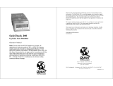
GX-3R
POW ER
MODE
CO/H
2
SLELO2
AIR
Bottom
Cover
Charging
Socket
Sensor
Retainer
Buzzer
Opening
Front Back
LCDLEDs
Threaded
Inserts
Figure 1: Component Location

GX-3R Pro Operator’s Manual Chapter 2: Description • 13
Control Buttons
Two control buttons, AIR and POWER MODE are located below the LCD.
Alarm LEDs
Five sets of red alarm LEDs (light emitting diodes) around the edge of the case alert you to
gas, low battery, and failure alarms.
Buzzer
One solid-state electronic buzzer is located inside the case. Sound exits the case through a
hole in the middle front of the case. The buzzer sounds for gas alarms, malfunctions, low
battery voltage, and as an indicator during use of the GX-3R Pro’s many display and
adjustment options.
Vibrator
A vibrating motor inside the GX-3R Pro case vibrates for gas alarms, unit malfunctions, and
as an indicator during normal use of the various modes of the GX-3R Pro.
NOTE: If STEALTH is set to ON, the vibrator only functions when VIBRATION in the
STEALTH Gas Select Mode item is set to ON. See “Stealth and Vibrator Settings
(STEALTH)” on page 160.
Sensors
The GX-3R Pro uses four sensors to monitor up to 5 gases simultaneously. The sensor retainer
and bottom cover hold the sensors in place. The sensors use different detection principles, as
described below.
Combustible Gas Sensor
The combustible gas sensor detects combustible gas in the % LEL range using a catalytic
element. The element’s resistance changes based on the reaction of gas with oxygen. The
change in resistance affects the current flowing through the element. The GX-3R Pro’s
circuitry amplifies the current, converts the current to a gas concentration, and displays the
concentration on the LCD.
Table 5: GX-3R Pro Control Button Functions
Button Function(s)
AIR • turns on LCD backlight
• resets alarm condition if LATCHING is set to ON in Maintenance Mode
• enters User Mode, Maintenance Mode, and Gas Select Mode when used
with POWER MODE button
• activates the demand zero function (adjusts the GX-3R Pro’s fresh air
reading)
• changes the value of a parameter available for adjustment
• scrolls through parameter options
POWER MODE • turns the GX-3R Pro on and off
• turns on LCD backlight
• enters and scrolls through Display Mode
• enters instructions into the GX-3R Pro’s microprocessor
• resets alarm condition if LATCHING is set to ON in Maintenance Mode
• enters User Mode, Maintenance Mode, and Gas Select Mode when used
with AIR button

14 • Chapter 2: Description GX-3R Pro Operator’s Manual
The standard calibration for the combustible gas sensor is to methane but the sensor will still
detect and respond to a variety of combustible gases.
O
2
/CO/H
2
S/Super Toxic Sensors
The O
2
, CO, H
2
S, and super toxic sensors are electrochemical cells that consist of two
precious metal electrodes in a dilute acid electrolyte. A gas permeable membrane covers the
sensor face and allows gas to diffuse into the electrolyte. The gas reacts in the sensor and
produces a current proportional to the concentration of the target gas. The GX-3R Pro’s
circuitry amplifies the current, converts the current to a gas concentration, and displays the
concentration on the LCD.
There are 4 different types of CO and H
2
S sensors available:
• CO only (ESR-A13P-CO): A single electrochemical cell that detects CO.
•H
2
compensated CO (ESR-A1CP-CO-H): A single electrochemical cell that detects CO.
This sensor does not respond to or responds minimally to hydrogen (displays H2 RICH
once H
2
concentration reaches 2000 ppm).
•H
2
S only (ESR-A13i-H2S): A single electrochemical cell that detects H
2
S.
•CO/H
2
S (ESR-A1DR-COHS): A combination electrochemical cell that detects both CO
and H
2
S.
IR Sensors
The infrared sensors detect CO
2
in the ppm and %volume ranges. Gas enters the sensor
through an opening on its face. Infrared light shines through the gas and into an infrared
detector. The intensity of the infrared light changes with the gas concentration and this change
is converted to an electrical signal. The GX-3R Pro’s circuitry converts the signal into a gas
concentration and displays the gas concentration on the LCD.
Dummy Sensors
A dummy sensor is installed in any units that have less than 4 sensors. Dummy sensors are
factory installed. The flat side of the dummy sensor faces away from the GX-3R Pro and the
hollow side faces toward the GX-3R Pro.
Filters
Combustible Gas Sensor H
2
S Removal Filter Disk (Dark Red)
An H
2
S removal filter disk is placed into a recess in the filter gasket over the combustible gas
sensor. The filter disk prolongs the life of the combustible gas sensor by preventing H
2
S in the
ambient air from reaching the sensor. The H
2
S filter disk is dark red in color and although it
may darken over time, its color is not indicative of remaining filter life.
The H
2
S filter disk needs replacing once it’s been exposed to 33 ppm hours of H
2
S. This
means the filter needs replacing after 80 minutes of exposure to 25 ppm H
2
S which equates to
40 2-minute calibrations with a cylinder containing 25 ppm H
2
S. If H
2
S exists in the
monitoring environment, the H
2
S filter disk will have to be replaced more frequently.
CO/H
2
S Sensor Dual Filter (Black and White)
A dual filter is placed into a recess in the filter gasket over the dual CO/H
2
S sensor. The black
half is a charcoal filter for the CO sensor. The white half is a humidity filter for the H
2
S
sensor.
Replace the filter if you notice:
• Unexplained CO readings.
• For users with a 1 ppm H
2
S alarm setpoint: A drift on the H
2
S zero reading,

GX-3R Pro Operator’s Manual Chapter 2: Description • 15
unexplained H
2
S readings, the filter appears dirty, or every 6 months (whichever is
sooner).
CO Sensor Charcoal Filter (Black)
A black charcoal filter is placed into a recess in the filter gasket over the CO sensor. The
charcoal filter disk scrubs H
2
S and certain hydrocarbons out of the sample to avoid false CO
readings. If false or elevated CO readings are noticed, especially in the presence of H
2
S,
change the charcoal filter.
H
2
S Sensor Humidity Filter (White)
A white humidity filter covers the H
2
S sensor. The filter absorbs humidity in the sampling
environment to prevent unstable readings around 0 ppm H
2
S. For users with a 1 ppm H
2
S
alarm setpoint, the filter should be replaced every 6 months, if you notice a drift on the zero
reading, or if the filter appears dirty (whichever is sooner). For users with a 2 ppm or higher
H
2
S alarm setpoint, the filter does not necessarily ever need to be replaced.
SO
2
Sensor H
2
S Removal Filter Disk (Tan)
An H
2
S removal filter disk is placed into a recess in the filter gasket over the SO
2
sensor (if an
SO
2
sensor is installed). The filter disk prolongs the life of the SO
2
sensor by preventing H
2
S
in the ambient air from reaching the sensor. The filter should be replaced every 6 months.
Hydrophobic Dust Filter
The oval-shaped hydrophobic dust filter is attached to the top of the filter gasket, covering the
sensor ports and the filters. The filter gasket and hydrophobic dust filter get replaced as a set.
NOTE: Some GX-3R Pros have a hydrophobic dust filter that is not attached to the filter
gasket. When replacing the hydrophobic dust filter on one of these GX-3R Pros,
remove the filter and the gasket and replace it with a filter gasket/hydrophobic dust
filter assembly.
Infrared Communications Port
An infrared (IR) communications port is located on the top of the case, near the top LEDs.
Logged data transmits through the port in standard IrDA protocol. A computer’s infrared port
or an IrDA/USB cable connected to a USB port can be used to download data to the GX-3R
Data Logger Management Program. See the GX-3R Data Logger Management Program
operator’s manual for data logging and downloading instructions.
Battery Pack
The GX-3R Pro is either powered by a rechargeable lithium-ion (Li-ion) battery pack or an
alkaline battery pack with 2 AAA batteries (Duracell MN2400 or PC2400). Instruments with
a Li-ion battery pack have a charging socket on the back of the instrument. Instruments with
an alkaline battery pack have a cover that allows for battery replacement.
The battery icon in the upper right of the LCD shows remaining battery life. A low battery
warning activates when the GX-3R Pro detects a low battery voltage. The GX-3R Pro sounds
a dead battery alarm when battery voltage is too low for Measuring Mode.
NOTE: Use of batteries or battery chargers not specified by RKI Instruments, Inc. will
compromise the CSA classification and may void the warranty. See pg.98 and
pg.100 for more information.

16 • Chapter 2: Description GX-3R Pro Operator’s Manual
WARNING: To prevent ignition of a hazardous atmosphere, batteries must only be
changed or charged in an area known to be nonhazardous.
AVERTISSEMENT:Pour éviter l’inflammation d’une atmosphère dangereuse, les batteries
doivent uniquement être modifiés ou facturés dans une zone connue
comme non dangereuse.
Included Accessories
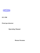
Alligator Clip
An alligator clip is installed on the back of the GX-3R Pro. The alligator clip can be used to
attach the GX-3R Pro to clothing or a belt. Teeth in the alligator clip’s jaws prevent the unit
from slipping off. The alligator clip can be rotated to change the instrument’s orientation.
Rubber Boot
A black rubber boot is installed on the GX-3R Pro.
Wrist Strap
A wrist strap is included with the GX-3R Pro and can be attached to the wrist strap installation
feature on the left side of the GX-3R Pro’s case.
Figure 2: Alligator Clip
Alligator
Clip

GX-3R Pro Operator’s Manual Chapter 2: Description • 17
Single-Unit AC Charger
The charging cable is a 4 foot cable with an AC adapter on one end and a charging plug that
connects to the GX-3R Pro on the other end.
Calibration Cup
Use the calibration cup to apply gas during a bump test, calibration, or gas test. The
calibration cup has an installation orientation to observe. “Front” and “rear” imprinting on the
bottom of the cup correspond to the front and rear of the GX-3R Pro when the calibration cup
is installed. In addition, a “front” label on the front of the calibration cup should be visible
when viewing the LCD with the calibration cup installed.
Other Accessories
12 VDC Charger
The 12 VDC charger is a 4 foot cable with a vehicle plug on one end and a plug that connects
to the GX-3R’s power jack on the other end.
Multi-Unit Charger
The multi-unit charger is a 4 foot wall plug style adapter that plugs into a bar. The bar has five
2-foot cables coming out one side. The end of each of the five cables has a plug that connects
to the GX-3R Pro’s power jack. The AC adapter is rated 100 - 240 VAC input, 5.99 VDC
output.
Figure 3: Charging Cable
AC Adapter
Charging
Plug
Figure 4: Calibration Cup
FRONT

18 • Chapter 2: Description GX-3R Pro Operator’s Manual
Belt Clip
A belt clip makes it easy to hook the GX-3R Pro to a utility belt.
SDM-3R
The SDM-3R is a calibration station for the GX-3R and GX-3R Pro. The station’s buttons can
be used for operations (Standalone Mode) or a computer can be used to control the docking
station (PC Controlled Mode). See the appropriate SDM-3R manual for more information.
RP-3R
The RP-3R is a pump that draws sample to the GX-3R Pro. See the RP-3R manual for more
information.
Aspirator Adapter
The aspirator adapter is a squeeze-bulb assembly that draws sample to the GX-3R Pro.
IrDA Cable
Unless your computer has a built-in IrDA port, an IrDA cable is needed to establish
communication between the GX-3R Pro and the Datalogging Program.
Figure 5: Belt Clip
Belt Clip

GX-3R Pro Operator’s Manual Chapter 3: Operation • 19
Chapter 3: Operation
Overview
This chapter explains how to perform confined space entry monitoring or general area
monitoring in the GX-3R Pro’s Measuring Mode.
Start Up
This section explains how to start up the GX-3R Pro, get it ready for operation, and turn it off.
NOTE: The screens illustrated in this section are for a 4-gas + 0 - 10.00% volume CO
2
unit.
The screens displayed by your GX-3R Pro may be slightly different.
Turning On the GX-3R Pro
To illustrate certain functions, the following description of the GX-3R Pro start up sequence
assumes that the following menu items are turned on: LUNCH BREAK, CAL REMINDER,
and BUMP REMINDER in User Mode, and ID DISPLAY and AUTO ZERO in
Maintenance Mode. If any of these items are turned off, then the corresponding screens will
not appear.
1 . Press and briefly hold down POWER MODE. Confirm that the LCD turns on, the LEDs
flash, the buzzer sounds, and the motor vibrates before continuing with operation.
Release the POWER MODE button when you hear a beep.
2 . If LUNCH BREAK is set to ON (factory setting is OFF, see pg.86), the Lunch Break
Screen appears. The unit counts down from 5 seconds.
a. Continue Accumulating: To continue accumulating peak and time-weighted average
(TWA) readings from the last time the GX-3R Pro was used, press and release
POWER MODE or allow the countdown to reach 0. The short-term exposure limit
(STEL) reading is reset each time the GX-3R Pro is turned on.
b. Reset Accumulation: To reset the accumulation of peak and time-weighted average
(TWA) readings, press and release AIR before the countdown reaches 0.
7:49
5 SEC
NO :AIR
LUNCH BREAK
7:49
5 SEC
YES :MODE
LUNCH BREAK

20 • Chapter 3: Operation GX-3R Pro Operator’s Manual
3 . If CAL REMINDER is set to ON (factory setting) and a calibration is due, the screen
that appears next depends on how CAL EXPIRED is set in User Mode (see pg.75). The
three possible screens are described below. If a calibration is not due, the instrument
displays the number of days left until a calibration is due.
CAL EXPIRED set to
CONFIRM TO USE (factory setting)
CAL EXPIRED set to
CANNOT USE
CAL EXPIRED set to
NO EFFECT
LCD
Sound Buzzer sounds double pulsing tone Buzzer sounds double pulsing tone None
Action • Option A, Perform calibration
: Press
and release POWER MODE to
perform a calibration. The instrument
takes you straight to the AUTO CAL
CYLINDER A screen in User Mode’s
GAS CAL\AUTO CAL item. See
pg.61 for calibration instructions.
If the calibration is successful, the
screen above will not appear again
until the unit is due for calibration. If
the calibration is not successful, the
screen above will again appear in the
startup sequence.
• Option B, Bypass message
: To
continue without performing a
calibration, press and release AIR.
The GX-3R Pro cannot be used until a
successful calibration is performed.
Press and release POWER MODE to
perform a calibration. The instrument
takes you straight to the AUTO CAL
CYLINDER A screen in User Mode’s
GAS CAL\AUTO CAL item. If you
don’t press POWER MODE, the instru-
ment automatically goes to the AUTO
CAL CYLINDER A screen after 6 sec-
onds. See pg.61 for calibration instruc-
tions.
If the calibration is successful, the
screen above will not appear again until
the unit is due for calibration. If the cali-
bration is not successful, the screen
above will again appear in the startup
sequence.
• Option A, Perform calibration
: To
perform a calibration, press and
release POWER MODE. The
instrument takes you straight to the
AUTO CAL CYLINDER A screen in
User Mode’s GAS CAL\AUTO CAL
item.
• Option B, Bypass message
: To
continue without performing a
calibration, wait a few seconds for the
instrument to continue with its startup
sequence.
7:49
CONFIRM TO USE
USER MODE:MODE
NO :AIR
CAL DATE PAST
7:49
CANNOT USE
USER MODE:MODE
CAL DATE PAST
7:49
NO EFFECT
USER MODE:MODE
CAL DATE PAST
/