Page is loading ...

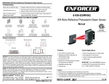
ENFORCER 50ft Reflective Photoelectric Beam Sensor
4 SECO-
LARM U.S.A., Inc.
WARRANTY
:
This SECO
-
LARM product is warranted against defects in material and workmanship while used in normal service
for a period of one (1) year from the date of sale to the original consumer customer. SECO-
LARM’s obligation is limited to the
repair or replacement of any defective part if the unit is returned, transportation prepaid, to SECO
-
This Warranty is void if damage is caused by or attributed to acts of God, physical or electrical misuse or abuse, neglect, r
or alteration, improper or abnormal usage, or faulty installation, or if for any other reason SECO-
LARM determines that such
equipment is not operating properly as a result of causes other than defects in material and workmanship.
The sole obligation of SECO-LARM, and the purchaser’s excl
usive remedy, shall be limited to replacement or repair only, at
SECO-LARM’s option. In no event shall SECO-
LARM be liable for any special, collateral, incidental, or consequential personal
or property damages of any kind to the purchaser or anyone else.
NOTICE:
The information and specifications printed in this manual are current at the time of publication. However, the
SECO-LARM policy is one of continual development and improvement. For this reason, SECO-
LARM reserves the right to
change specifications without notice. SECO-
LARM is also not responsible for misprints or typographical errors.
Copyright © 2016 SECO-
LARM U.S.A., Inc. All rights reserved. This material may not be reproduced or copied, in whole or in
part, without the written permission of SECO-LARM.
SECO
-
LARM
®
U.S.A., Inc.
16842 Millikan Avenue, Irvine, CA 92606
Website: www.seco-larm.com
Tel: 800-662-0800 / 949-261-2999 Fax: 949-261-7326
E-mail: info@seco-larm.com
Troubleshooting:
Sensor does not detect the object.
•
Change
the angle of the sensor or readjust
the sensitivity setting.
The beam sensor LED will not turn green.
•
Clean the sensor and reflector with a damp
(not wet) cloth.
•
Adjust the reflector and/or sensor for proper
alignment.
Beam sensor LED lights when
object
is detected, but there is no output.
•
Check wiring between the sensor and local
alarm device.
Sample Applications:
Garage
Door
Gate
Vehicle
Detection
Other Sensors Available:
Dual and
Quad Beam
Optional Accessory:
Reflector Hood
E-931ACC-HR1Q
Provides extra
protection for the
reflector.
Compatible with Reflective Photoelectric Beam Sensor models
E-931-S50RRGQ, E-931-S35RRQ, and E-931-S33PRGQ.
Reflective
Photobeam
LARM U.S.A., Inc.
LARM product is warranted against defects in material and workmanship while used in normal service
LARM’s obligation is limited to the
-
LARM.
This Warranty is void if damage is caused by or attributed to acts of God, physical or electrical misuse or abuse, neglect, r
epair,
LARM determines that such
equipment is not operating properly as a result of causes other than defects in material and workmanship.
usive remedy, shall be limited to replacement or repair only, at
LARM be liable for any special, collateral, incidental, or consequential personal
The information and specifications printed in this manual are current at the time of publication. However, the
LARM reserves the right to
LARM is also not responsible for misprints or typographical errors.
LARM U.S.A., Inc. All rights reserved. This material may not be reproduced or copied, in whole or in
MI_E
-
931
-
S50RRGQ_151215.docx
PITSW3
the angle of the sensor or readjust
the sensitivity setting.
Clean the sensor and reflector with a damp
Adjust the reflector and/or sensor for proper
Check wiring between the sensor and local
Assembly
Line
Other Sensors Available:
Dual and
Quad Beam
Curtain and
Barrier
E-931-S50RRGQ
50ft Reflective Photoelectric Beam Sensor
Manual
•
Up to 50ft (15m) sensing range
• Weatherproof (IP55)
• Anti-condensation housing
• 12-30V DC/AC 60Hz, 100mA
•
Form C relay:
0.5A
•
Beam status LED
• N.C. Tamper
switch:
500mA@30VA
Caution:
• This sensor is not designed to prevent bodily injury or loss of life.
• This sensor is not designed for use in
environments where explosive gasses may be present.
•
Use of this sensor in certain security applications may be regulated by local laws or codes. SECO
responsible for compliance with such laws or codes.
50ft Reflective Photoelectric Beam Sensor
0.5A
@30VAC/VDC
Beam status LED
switch:
500mA@30VA
C/VDC
environments where explosive gasses may be present.
Use of this sensor in certain security applications may be regulated by local laws or codes. SECO
-LARM is not

ENFORCER 50ft Reflective Photoelectric Beam Sensor
2 SECO-LARM U.S.A., Inc.
Specifications:
Model
E
-
931
-
S50RR
G
Q
Type
Reflective photoelectric
beam sensor
Sensing range
50ft (15m)
Operating voltage
12
-
30V DC/AC 60Hz, 100mA
Current
drain
Standby
55mA@12VDC
Active
40
mA@12VDC
Response time
10ms
Light source
IR LED
LEDs
Solid
Green
Good beam signal, properly aligned
Alternating flash
Poor
beam signal
Solid
Red
No beam signal, triggered
Trigger output
SPDT Relay output (NO/NC/COM)
Switching capacity
500mA@30VAC/VDC
Tamper switch
500mA@30
VAC/
VDC
IP Rating
IP55
Operating temperature
-13
°
~140
°
F (-25
°
~60
°
C)
Parts List:
1x Sensor
1x Reflector
1x Mounting bracket
1x Sensor hood
4x Cover screws
2x Mounting screws
1x Reflector mounting screw
1x Rubber ring
1x Cable connector
1x Manual
1x Removable terminal block
1x 10KΩ Resistor
Overview:
Tamper switch
Vertical
adjustment screw
(without cover)
Cover
Cover
screw
Wire cable connector
Mounting plate
Hood
Dimensions:
Beam
sensor LED
Terminal
block
Cable breakout
Captive screw
Beam sensor
4
13
/
16
”
(122mm)
3
/
16
”
(4mm)
3
1
/
4
”
(82mm)
3
/
8
”
(9mm)
2
1
/
8
”
(54mm)
2
3
/
8
”
(60mm)
1
15
/
16
”
(49mm)
2
7
/
16
”
(62mm)
Cable breakout
•
Polarity does not matter for the power input.
• Connect the N.C. tamper terminal to the
tamper circuit of an alarm control panel.
Wiring Diagram:
12
-
30V DC/AC
60Hz, 100mA
(Non-Polarity)
N.C.
N.O.
COM
Tamper
N.C.
Relay
Note:
Depending on the monitoring system used by the gate motor, it may be necessary to use either the N.C. output or
connect the included 10kΩ resistor to the N.O. or N.C. output. Please refer to the gate operator manual or the gate
operator manufacturer for the preferred monitoring method.
ENFORCER 50ft Reflective Photoelectric Beam Sensor
SECO-LARM U.S.A., Inc. 3
1.
Mount the sensor
and reflector so that they face
each other.
2. Connect power to the sensor. The LED will light
as indicated in the chart below.
3. Unscrew the four cover screws and remove the
cover.
4. To find the correct alignment, slowly turn the
lens assembly left and right to adjust the
horizontal angle.
5. Loosen the vertical adjustment screw to adjust
the vertical angle.
6. Place the hood on the sensor by sliding the
hood’s ridges into the slots on the sides of the
sensor.
7. Re-attach the cover, replace the four screws,
and attach the hood to the top of the sensor.
1.
Unscrew th
e
f
o
u
r
cover screws and remove the
cover.
2. Loosen the captive screw and remove the sensor
from the mounting plate.
3. Using the included mounting screws, mount the
mounting plate to the wall.
4. Use the cable breakout and cable connector at
the bottom or rear of the sensor to run the wires.
5. Hang the sensor back on the plate and use the
captive screw to secure it in place.
6. Re-attach the cover, replace the four screws, and
attach the hood to the top of the sensor.
Mounting:
Alignment:
Solid green
Good beam signal,
properly aligned
Alternating flash
Poor beam signal
Solid red
No beam signal,
triggered
Lens
alignment
±90
°
±5
°
Horizontal
adjustment
Vertical
adjustment
Wiring for the Bottom Cable Breakout
1.
Puncture
the cable breakout located at the bottom
of the sensor using a screwdriver or other object.
2. Insert the short end side of the cable connector
into the cable breakout hole and use the nut to
secure it, tightening with a wrench as needed.
3. Run the wires through the end cap and cable
connector.
4. Then screw the end cap into the external side of
the cable connector to prevent water from
entering the unit.
Cable
Connector
End cap
Sensor
Nut
Rubber
neck
/
