
JABLOTRON ALARMS a.s.
Pod Skalkou 4567/33 46601 Jablonec n. Nisou
Czech Republic www.jablotron.com
||
|
The JA-150M, JA-150MB, JA-150M-AN, JA-150M-GR
Wireless magnetic detector with 2 universal inputs
JA-150M, JA-150MB, JA-150M-AN, JA-150M-GR 1 / 2 MND51113
The JA-150M is a wireless component of the JABLOTRON system.
It is a magnetic detector with two configurable independent inputs.
The detector is also designed to detect the movement of roller blinds, if it
is equipped with a CT-01 roller detector. Small movements are filtered
out so that wind blasts do not cause false alarms. The module occupies
2 positions in the F-link device list. The JA-150M can be used with up to
two LD-81 flood detectors.
The product must be installed by a trained technician with a valid
certificate issued by an authorized distributor.
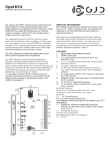
Figure: 1 – Place for locking screw, 2 – Cover tab, 3 – LED indication, 4 – Battery,
5 – Production number, 6 – DIP switch settings, 7 – Terminals,
8 – Cover tamper contact
Axis
X
Y
Z
Activation distance (mm)
25/7
14/9
44/25
Deactivation distance (mm)
24/6
13/8
43/24
Table 1: Spacing on a non-magnetic surface. Distances are issued for device
using ferrite magnet / ring magnet.
Axis
X
Y
Z
Activation distance (mm)
17/9
11/4
43/18
Deactivation distance (mm)
16/8
10/3
42/17
Table 2: Spacing on a magnetic surface. Distances are issued for device using
ferrite magnet /ring magnet.
There are two different types of permanent magnets in the package –
a ferrite magnet in a plastic housing (A) and a neodymium ring magnet
(B) for use in places where there is not enough space for a standard
magnet or for counter-sinking the magnet into a door’s or window’s inner
frame. The positions for placing both types of magnets against
the internal magnetic sensor are shown above (see Figure) as well as
the reaction areas for magnets in millimetres in three axes of movement
(see Table 1 and 2). The polarity of the magnet can affect the change in
detection distance.
Installation
1. Open the detector cover by pressing the cover tab (2).
2. Screw the rear cover onto the required place. If it´s needed, put
the cables through the rear plastic base. The length of cables
to the detector should not exceed 3 m; choose the place
of installation accordingly.
3. Attach the selected magnet to the moving part of the door (window)
with screws. The lower edge of the ferrite magnet must be at
the same height as the lower edge of the detector. It is recommended
to attach the ring magnet with a special non-magnetic screw from
the package.
4. Connect the wires from external contact to the required terminals
if they are used.
5. It is not necessary to use any wire jumpers if none of the terminals
will be used (this is also valid for tamper).
6. Set the DIP switches according to your needs (see Table 3).
7. Proceed according to the control panel installation manual.
Basic procedure:
a. Go to the F-link software, select the required position in
the Devices window and launch the enrollment mode by
clicking on the Enroll option.
b. Insert the batteries (mind the correct polarity). The enrolment
signal is transmitted when the battery is inserted into
the detector. Note – the detector occupies 2 positions (each
input has its own position). If the second position
is occupied, it will be automatically overwritten.
8. Close the detector cover.
Note:
− The detector can also be enrolled into the system by entering its serial
number (5) in the F-link software (1400-00-0000-0001). You can find
the production code on the sticker under the bar code on the battery
holder.
− If only the first input is used, the second input can be deleted by pressing
“Delete” to release the position for another device.
− By deleting the first input position, the module will always be deleted
completely.
Setting the detector properties
This can be done by DIP switches 1-4 on the detector’s PCB. Select
the required mode according to Table 2. The detector immediately reads
the NO/NC status of all input terminals when the battery is inserted.
The detected NC or NO state is taken as the default (standby). The input
terminals IN1 and IN2 also work with 1k resistor-balancing.
Example: When there is a requirement to change the default logic of IN1
from NC to NO it is necessary to insert the battery when the input
is disconnected.
Description of inputs:
IN1 – Input terminal for connection to detector no. 1
IN2 – Input terminal for connection to detector no. 2
TMP – Input terminal for tamper contact connection
COM – Common terminal for inputs IN1, IN2 and TMP
MG – Internal magnetic detector
Description of input modes:
Norm – status mode, the detector signals activation and deactivation
of the input terminals
Pulse – pulse mode, the detector just signals activation (whether
turning off or turning on depends on the default NO/NC standby mode)
Off – input disabled
Rol1, Rol2 – roller mode, which reacts to repeated pulses and short
activating (NO) pulses with a sensitivity selectable in to two levels: Rol1 =
activation after 3 pulses within a 2-minute period; Rol2 = activation after
5 pulses within a 2-minute period. After input is triggered in Rol1/Rol2 mode,
the detector does not react to the next activation for 10 s. LD-81 – mode for
connecting one or two LD-81 flood detectors. If there are two flood detectors
used simultaneously, alarm will always be triggered only from the first detector
(logic OR function).
Table 3: Setting the detector properties (• = DIP switch ON)
Mode
DIP1
DIP2
DIP3
DIP4
MG
IN1
IN2
0
Norm
Off
Norm
1
•
Norm
Off
Pulse
2
•
Norm
Off
Rol1
3
•
•
Norm
Off
Rol2
4
•
Pulse
Off
Pulse
5
•
•
Pulse
Off
Rol1
6
•
•
Pulse
Off
Rol2
7
•
•
•
Off
LD-81
LD-81
8
•
Off
Norm
Norm
9
•
•
Off
Norm
Pulse
10
•
•
Off
Norm
Rol1
11
•
•
•
Off
Norm
Rol2
12
•
•
Off
Pulse
Pulse
13
•
•
•
Off
Pulse
Rol1
14
•
•
•
Off
Rol1
Rol1
15
•
•
•
•
Off
Rol2
Rol2

The JA-150M, JA-150MB, JA-150M-AN, JA-150M-GR
Wireless magnetic detector with 2 universal inputs
JA-150M, JA-150MB, JA-150M-AN, JA-150M-GR 2 / 2 MND51113
Battery replacement
The system sends a report automatically when the battery is low.
Remember to switch the system to Service mode before changing
the batteries (otherwise a tamper alarm will be triggered). Warning:
The input terminals must be in standby mode when a new battery is
inserted, the detector reads the inputs and takes the status as default.
(This is not valid for an internal magnetic contact).
Technical specifications
Power 1x alkaline battery, type AA (LR6 1.5 V/2.4 Ah)
Please note: Battery is not included
Typical lifetime of battery about 2 years (max. 10 activation daily)
LowBatt state <0.92 V
Quiescent current consumption 40 µA
Maximum current consumption 120 mA
Communication frequency 868.1 MHz, JABLOTRON protocol
Maximum radio-frequency power (ERP) 13 mW
RF range approx. 300 m (unrestricted area)
The maximum length of cable for external detectors 3 m
Dimensions transmitter part 24 x 109 x 24 mm
Dimensions magnet part 16 x 55 x 15 mm
Weight (without battery) 55 g
Classification Security grade 2/Environmental class II (EN 50131-1)
Operational environment Indoor general
Operational temperature range -10 °C to +40 °C
Average operating humidity 75 % RH, without condensation
Certification body Trezor Test s.r.o. (no. 3025)
Complies with EN 50131-1, EN 50131-2-6, EN 50131-5-3
ETSI EN 300 220-1-2, EN 50130-4, EN 55032, EN 62368-1,
EN IEC 63000
Can be operated according to ERC/REC 70-03
Recommended screw 2 x ø 3.5 x 40 mm (countersunk head)
JABLOTRON ALARMS a.s. hereby declares that the JA-150M,
JA-150MB, JA-150M-AN, JA-150M-GR
is in compliance with
the relevant European Union harmonisation legislation: Directives
No: 2014/53/EU, 2014/35/EU, 2014/30/EU, 2011/65/EU, when used
as intended. The original of the conformity assessment can be found
at www.jablotron.com – the Downloads Section.
Note: Disposing of this product correctly will help save valuable
resources and prevent any potential negative effects on human
health and the environment, which could otherwise arise from
inappropriate waste handling. Please return the product to the dealer
or contact your local authority for further details of your nearest
designated collection point.
-
 1
1
-
 2
2


Ask a question and I''ll find the answer in the document
Finding information in a document is now easier with AI
Related papers
-
Jablotron JA-60N Owner's manual
-
Jablotron JA-183M User manual
-
Jablotron JA-151M Operating instructions
-
Jablotron JA-111M User manual
-
-
-
-
-
-
Other documents
-
Roger PR821-CH User manual
-
 GJD GJD017 User manual
-
 King Pigeon S800 User manual
-
Eldes Pitbull Alarm User manual
-
Eldes EWF1 User manual
-
-
-
-
Satel AXD-200 User manual
-
Risco RWX73F User manual

