Siemens VNT User manual

Type
User manual

Siemens VNT is a fanless single board computer that acts as a gateway, supporting intercommunication of system components. It transports supervision and monitoring data between VNTs via TCP/IP and routes audio when required. Features include:

  • 100BaseT TCP/IP connection to a local Fiber Ring Switch for network signals, audio, supervision, and monitoring data streams
  • One or more independent HNET RS485 interfaces to the module network
  • An XNET RS485 interface to the XLS/Desigo nodes within a system
  • An XNET over TCP/IP feed to an NCC at a command center
  • An HNET RS485 interface to an XLS/Desigo node within a system
Siemens Siemens
Siemens Siemens
Siemens IndustryIndustry
IndustryIndustry
Industry,,
,,
, Inc. Inc.
Inc. Inc.
Inc.
Building Building
Building Building
Building
TT
TT
Tecec
ecec
echnologies Dihnologies Di
hnologies Dihnologies Di
hnologies Divisionvision
visionvision
vision
P/N 315-050490-3
Virtual Network Tunnel
Installation Instructions
Model VNT
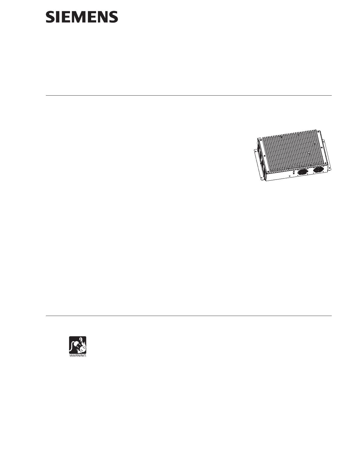
INTRODUCTION The Model VNT Virtual Network Tunnel (as shown in Figure 1) from Siemens Industry,
Inc. is a UL approved fanless single board computer that is powered from its local
24V power supply with battery back up. The VNT Gateway is responsible for support-
ing the intercommunication of system components.
It transports HNET and XNET supervision and
monitoring between VNTs via TCP/IP. It also routes
audio over TCP/IP when required between VNTs. If
the VNT Gateway is at a control point, it is respon-
sible for generating audio from the local source.
The VNT Gateway utilizes some or all of the
following interfaces depending upon its location
within the system:
100BaseT TCP/IP connection to a local Fiber Ring Switch. This connection
transports the network signals (HNET and XNET), audio, supervision and
monitoring data streams.
One or more independent HNET RS485 interfaces to the module network of an
XLS/Desigo Fire Safety Modular/Cerberus PRO Modular or its components.
An XNET RS485 interface to the XLS/Desigo Fire Safety Modular/Cerberus
PRO Modular node(s) within a given system.
An XNET over TCP/IP feed to an NCC at a command center.
An HNET RS485 interface to an XLS/Desigo Fire Safety Modular/Cerberus
PRO Modular node within a given system.
An audio input to accept a microphone paging source.
An audio output to distribute paging audio to a given system.
INSTALLATION The VNT mounts on a VNT-MP in a CAB1, CAB2 or CAB3 enclosure. Refer to the VNT-MP
Installation Instructions, P/N 315-050489, for information on mounting the VNT-MP.
Remove all system power before installation, first battery then AC. (To power up,
connect the AC first, then the battery.)
The following items are supplied with the VNT (P/N 500-650490):
QuantityItem
1 VNT fanless computer
1 Cable P/N 555-150464
1 Cable P/N 555-150494 (to fiber switch)
4 #8-32 hex nuts
Figure 1
Virtual Network Tunnel
firealarmresources.com
Siemens Industry, Inc.
Building Technologies Division
P/N 315-050490-32
VNT Mounting Refer to Figure 2.
The VNT mounts at the top of the VNT mounting plate with the four hex nuts provided.
1. Place the VNT over the four studs on the VNT-MP.
2. Place the four hex nuts supplied over the studs and tighten them to secure
the VNT to the VNT-MP.
VNT
STUDS (4) FOR
MOUNTING VNT
VNT-MP
FIBER SWITCH
MOUNTING RAIL
XND BRACKET
Figure 2
Mounting the VNT to the VNT-MP
WIRING Wiring for the VNT-Building Configuration is shown in Figure 3. Wiring for the VNT-Fire
Command Center is shown in Figure 4.
All connections are supervised and power limited unless otherwise stated.
ELECTRICAL RATINGS For power, the VNT may only be connected to the VNT-PS (P/N 500-450491).
Input Voltage: Regulated 24VDC
Input Current: 1.7A @ 24VDC max.
firealarmresources.com
Siemens Industry, Inc.
Building Technologies Division
P/N 315-050490-33
FIRE SYSTEM
TO
P5
11
19
1
1
+
+
+
_
_
_
2
2
H
N
GND
6
24
12
18
7
13
12
34
TB1
TB2
BATTERY
P9 P12
TB3
TB4
P4
OFF
O
ON
P10
HNET/CAN
1
2
3
4
5
1
2
3
4
5
P3
1 2
E5
Figure 3
Connection Diagram for VNT-Building
firealarmresources.com
Siemens Industry, Inc.
Building Technologies Division
P/N 315-050490-34
Figure 4
Connection Diagram for VNT-FCC (Fire Command Center)
P5
11
19
1
1
+
+
+
_
_
_
2
2
H
N
GND
6
24
12
18
7
13
12
34
TB1
TB2
BATTERY
P9 P12
TB3
TB4
P4
OFF
O
ON
P10
HNET/CAN
1
2
3
4
5
P3
P2P5
P7 P4 P3
13
*GND
(GND IS THICK
BLACK WIRE.
CUT THIN
BLACK WIRE.)
E5
1
2
3
4
5
6
7
8
9
0
1
2
3
4
5
6
7
8
9
0
1
2
3
4
5
6
7
8
9
0
1
2
3
4
5
6
7
8
9
0
1
2
3
4
5
6
7
8
9
0
1
2
3
4
5
6
7
8
9
0
1
2
3
4
5
6
7
8
9
0
1
2
3
4
5
6
7
8
9
0
1
2
3
4
5
6
7
8
9
0
1
2
3
4
5
6
7
8
9
0
1
2
3
4
5
6
7
8
9
0
1
2
3
4
5
6
7
8
9
0
1
2
3
4
5
6
7
8
9
0
1
2
3
4
5
6
7
8
9
0
1
2
3
4
5
6
7
8
9
0
1
2
3
4
5
6
7
8
9
0
LCM-8
OR
SCM-8
LCM-8
OR
SCM-8
LCM-8
OR
SCM-8
LCM-8
OR
SCM-8
LCM-8
OR
SCM-8
LCM-8
OR
SCM-8
LCM-8
OR
SCM-8
LCM-8
OR
SCM-8
P1
P2
P1
P2
P1
P2
P1
P2
P1
P2
P1
P2
P1
P2
P1
P2
Buzzer
12345678 12345678
1
2
3
4
5
6
7
8
9
0
1
2
3
4
5
6
7
8
9
0
1
2
3
4
5
6
7
8
9
0
1
2
3
4
5
6
7
8
9
0
1
2
3
4
5
6
7
8
9
0
1
2
3
4
5
6
7
8
9
0
1
2
3
4
5
6
7
8
9
0
1
2
3
4
5
6
7
8
9
0
LCM-8
OR
SCM-8
LCM-8
OR
SCM-8
LCM-8
OR
SCM-8
LCM-8
OR
SCM-8
P1
P2
P1
P2
P1
P2
P1
P2
*
*
CAN TERMINATOR
P/N 110-134215
BLACK
RED
WHITE
GREEN
WHITE
BLACK
WHITE
firealarmresources.com
Siemens Industry, Inc.
Building Technologies Division
P/N 315-050490-35
Cyber security disclaimer
Siemens products and solutions provide security functions to ensure the secure operation of building comfort,
fire safety, security management and physical security systems. The security functions on these products and
solutions are important components of a comprehensive security concept.
It is, however, necessary to implement and maintain a comprehensive, state-of-the-art security concept that is
customized to individual security needs. Such a security concept may result in additional site-specific preventive
action to ensure that the building comfort, fire safety, security management or physical security system for your
site are operated in a secure manner. These measures may include, but are not limited to, separating networks,
physically protecting system components, user awareness programs, defense in depth, etc.
For additional information on building technology security and our offerings, contact your Siemens sales or
project department. We strongly recommend customers to follow our security advisories, which provide infor-
mation on the latest security threats, patches and other mitigation measures.
http://www.siemens.com/cert/en/cert-security-advisories.htm
firealarmresources.com
Siemens Industry, Inc.
Building Technologies Division
P/N 315-050490-36
THIS PAGE HAS BEEN LEFT INTENTIONALLY BLANK.
firealarmresources.com
Siemens Industry, Inc.
Building Technologies Division
P/N 315-050490-37
THIS PAGE HAS BEEN LEFT INTENTIONALLY BLANK.
firealarmresources.com
Siemens Industry, Inc.
Building Technologies Division
Florham Park, NJ
Siemens Canada, Ltd.
1577 North Service Road East
Oakville, Ontario
L6H 0H6 Canada
P/N 315-050490-3Document ID A6V10316286
firealarmresources.com
  • Page 1 1
  • Page 2 2
  • Page 3 3
  • Page 4 4
  • Page 5 5
  • Page 6 6
  • Page 7 7
  • Page 8 8

Siemens VNT User manual

Type
User manual

Siemens VNT is a fanless single board computer that acts as a gateway, supporting intercommunication of system components. It transports supervision and monitoring data between VNTs via TCP/IP and routes audio when required. Features include:

  • 100BaseT TCP/IP connection to a local Fiber Ring Switch for network signals, audio, supervision, and monitoring data streams
  • One or more independent HNET RS485 interfaces to the module network
  • An XNET RS485 interface to the XLS/Desigo nodes within a system
  • An XNET over TCP/IP feed to an NCC at a command center
  • An HNET RS485 interface to an XLS/Desigo node within a system

Ask a question and I''ll find the answer in the document

Finding information in a document is now easier with AI