Quick Installation Guide
for LG ESS Home 8 (RBA008K0A00)
Important Safety Instruction
IMPORTANT: This product should not be used for any purpose other
than the purpose described in the installation manual.
indicates a hazardous situation that will result in death or
serious injury if the instruction is not followed.
yDo not open the door. There are no user serviceable parts inside.
Service may be performed only by trained service provider.
yRisk of electric shock from energy stored in capacitor. Do not
remove the door until 10 minutes after disconnecting all sources
when service needed.
yElectric shock hazard. Do not touch uninsulated wires when the
product cover is removed.
yDo not disconnect, disassemble, or repair to avoid injuries, electric
shock or burns.
yThere is a high possibility of electric shock or serious burns due to
the high voltages in the ESS.
yThe AC cables are high voltage. Risk of death or serious injury due
to electric shock.
yThis product poses potential danger such as death or serious injury
by re, high voltages, or explosion if appropriate precautions are not
read, fully understood, and followed.
yDo not place or install ammable or potentially explosive objects
near the product or in explosive atmospheres.
yDo not charge or discharge arbitrarily. It may lead to fault, electric
shock, or burns.
yDo not damage the unit in any manner, such as by dropping,
deforming, impacting, cutting, or spearing with a sharp object. It
may cause electrolyte leakage or re.
yBreakdown of the unit may cause electrolyte leakage or ammable
gas generation.
yIf electrolytes leak, avoid contact with eyes, skin, or clothes. In
event of accidental contact, ush with water and seek medical help
immediately.
yDo not place near open ame or incinerate. It may lead to re or
explosion.
yKeep the unit away from moisture or liquid. Do not touch or use the
product if liquids have been spilled on it.
yKeep out of reach of children or animals.
yElectrical installations must be done in accordance with
local standards, national electrical safety standards, and the
manufacturer’s instructions.
yThe battery system is a bidirectional source of voltage. The battery
circuit breaker and inverter must both be off before working in the
wiring box.
yDisconnect each circuit individually before servicing. Both AC and
DC voltage sources are terminated inside this equipment.
yDo not dispose of batteries in a re. The batteries may explode.
yDo not open or assemble while product is working.
Indicates a potentially dangerous situation. Death or serious
injury may result if appropriate precautions are not taken.
yA potentially hazardous circumstance such as excessive heat or
electrolyte mist may occur due to improper operating conditions,
damage, misuse and/or abuse.
yThe contents included in this box are the ESS and its accessories.
The total weight is very heavy. Serious injury may occur due to
the weight of the package containing the ESS and accessories.
Therefore, special care must be taken in handling. Make sure to use
the handle lift to deliver and install the package.
yDo not open or damage batteries. Released electrolyte is harmful to
the skin and eyes. It may be toxic.
yDo not place heavy objects on this product. It may cause
deformation or fracture.
yDo not place any kind of objects on top of the product during
operation.
yAll work on the ESS must be carried out by trained service providers
only.
yElectrical installations must be done in accordance with the local
and national electrical safety standards.
yWear rubber gloves and protective clothing (including protective
glasses and boots) when working on the ESS.
yTo reduce the risk of re, do not connect to an AC load center
(circuit breaker panel) with multiwire branch circuits connected.
Indicates a situation where damage or injury may occur. If it is
not avoided, minor injury and/or damage to property may result.
yBefore testing electrical parts inside the system, there is a minimum
of a 10 minute standby period to completely discharge the system.
yDo not use any damaged, cracked, or frayed electrical cables or
connectors. Protect the electrical cables from physical or mechanical
abuse, such as being twisted, kinked, pinched, closed in a door,
or stepped on. Periodically examine the electrical cables of your
product. If the appearance indicates damage or deterioration,
discontinue use of this product and have the cables replaced with
an exact replacement part by a qualied personnel.
yEnsure that you connect the earth ground wire to prevent possible
electric shock. Do not try to ground the product by connecting it to
telephone wires, lightning rods, or gas pipes.
yDo not put the product or components in water or liquid.
yMake sure that there are no water sources, such as faucets or
sprinklers, near the installation site.
yDo not block any ventilation openings. Ensure reliable operation
of the product and protect it from overheating. Do not block any
openings by placing objects on this product.
yThe metal enclosure may heat to a high temperature during
operation.
yThe product must be disposed of according to local regulations.
yIf the ESS is not operated for a long time, the battery may be
overdischarged.
yDo not step on the product or the product package. The product
may be damaged.
yBatteries may present a risk of electrical shock and high short-
circuit current. The following precautions should be observed when
working on the ESS system include:
a) Remove watches, rings, and other metal objects.
b) Use tools with insulated handles.
c) Wear rubber gloves, boots, and glasses.
d) Do not lay tools or metal parts on top of the system.
yIn the event of fault, the system must not be restarted. Product
maintenance and repairs must be performed by trained service
providers.
yIf a system fault occurs immediately after starting the system,
check the error code on the Smart Energy Box (SE Box) display and
follow the solution described in the manual.
Indicates a risk of possible damage to the product.
yThis product is intended for residential use only and is not intended
for use in industrial Purposes.
yThe System consists of Home 8 and SE Box. They must be
installed together and it will not work when installing unauthorized
components to the system.
yThe unit is designed to feed power to the public grid only. Do not
connect the unit to a generator as connecting the power to external
devices could result in serious damage to the equipment.
yLG ESS Home 8 performs best when it is connected to the internet
and registered through the ThinQ service, so that the rmware may
be remotely updated periodically.
yFor the latest ESS documents, visit:
- Warranty : https://www.lg.com/us/ess/warranty
- Installation Manual : https://www.lg.com/us/ess/Installationmanual
- User Manual : https://www.lg.com/us/ess/usermanual
- Quick Installation Guide : https://www.lg.com/us/ess/quickstart
yIf the S/W version is not up to date during installation, update the
S/W using a FAT32 formatted USB storage device. When the SE
Box is connected to Ethernet through a LAN cable after normal
operation, it is automatically updated to the latest S/W version.
yHandling of batteries should be performed or supervised by a
trained service provider.
yThe battery does not discharge when the load is under a certain
level.
yTo prevent network problems, check the “Network Settings” before
installation.
yDo not store or place any objects on top of or against the unit. It
may cause serious malfunction or other problems.
yNever use any solvents, abrasives, or corrosive materials to clean
this unit.
yUnder backup operation, whether the battery SoC is higher than
90% or the ESS needs to reduce the charging power, the ESS may
reduce the solar power generation.
yIf the battery SoC is too low during backup operation during a
power outage, the system operates as follows.
-Even though the PV system is equipped, the system will not supply power
to the home load. However, the system can charge the battery from the
PV system rst and then supply power to the home again if the battery
SoC is sufciently charged.
-If the PV system is not equipped, the system cannot supply power to the
home load and the system will go into sleep mode.
Contact
If there are any errors occurred, you can check it on Home 8 LED
Indicators or HMI Display of SE Box.
Please check Error Code by referring to installation manual or user
manual.
If you have any technical problems or questions, contact the
installation company or LGEUS.
LG Electronics ESS Service
ATTN: Electro-Tech Services, Inc. 11149 Arrow Route, Rancho
Cucamonga, CA 91730
(833) 940-5010
Using LG ThinQ® Applications (For User)
yTo use the LG ThinQ® Application, the SE Box must be connected to
the Internet.
yFor more information, please refer to the Installation Manual or the
User Manual.
INFO
1. Download ‘LG ThinQ®’ application in the Google® Play Store or Apple®
App Store® on a mobile phone.
2. Registering the system
Create an account and sign in. > Select [Add a Device] > [Select Device]
> Select [ESS Home].
3. On your SE Box display, press [ ] > [Settings] > [General Settings].
4. Set the [Soft AP] option to [Active] state.
Installation Location
33°C
(91.4°F)
0°C
(32°F)
3 000 m
(9842 ft) > 95%
yIndoors installation is recommended in cold climates regions below 0°C
(32°F).
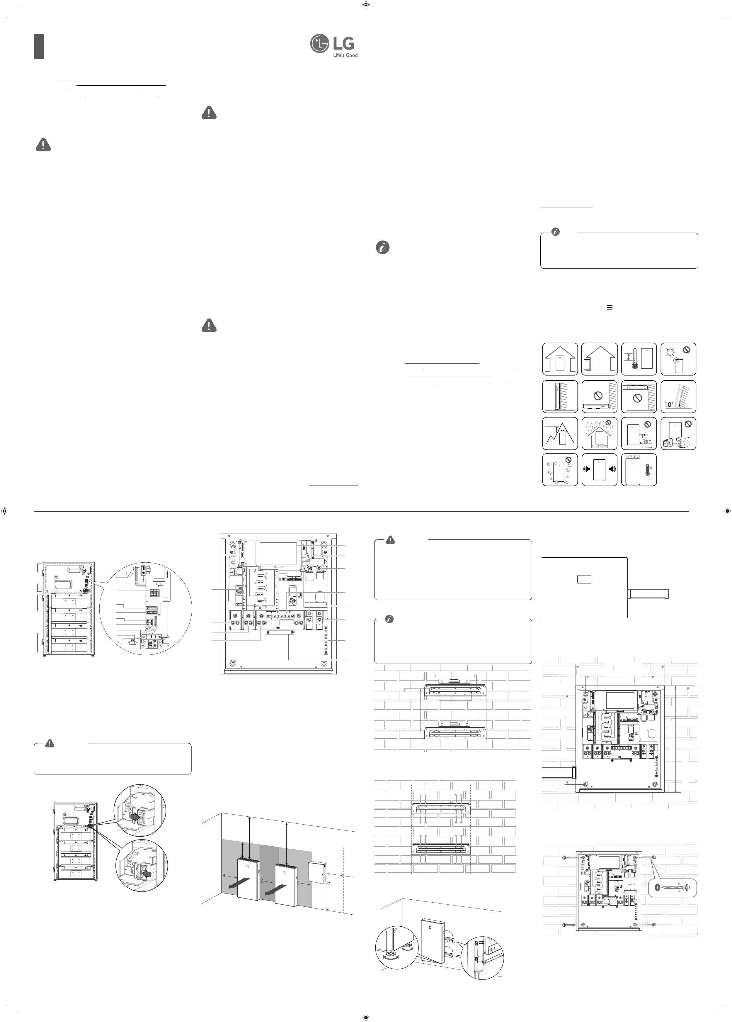
Part Names
Connection parts (Home 8)
1 2
PCSBattery
A
B
C
D
E
F
G
H
A DIP switches
B AC power terminals (L1, Neutral, L2) (CN_GRID)
C Communication terminal block (to another Home 8) (CN_PCS)
D Communication terminal block (to the SE Box) (CN_ATS)
E Ground terminal (Protective Earth terminal, AC Power)
F Ground terminal (Protective Earth terminal, Communication)
G Battery fuse
H Battery circuit breaker
The battery packs and harness contain high voltages. Risk of death or
serious injury due to electric shock. Before working on any Home 8
wiring, make sure the Home 8 battery circuit breaker is set to OFF.
WARNING
Connection Parts (SE Box)
A
F
G
H
K
J
I
L
M
B
C
D
E
A Communication terminal (to Home 8) (CN1000)
B Panelboard
C Backup load terminals (L1)
D Backup load terminals (L2)
E Neutral terminals for grid and load
F HMI (Human Machine Interface) display
G Grid terminal (L2)
H Grid terminal (L1)
I Neutral terminals for Home 8 and
PV inverter
J Non-backup load terminals (L2)
K Non-backup load terminals (L1)
L Ground terminals for grid and load
M Ground terminals for Home 8 and PV inverter
Minimum Clearance
915 mm
(36 inches)
878 mm
(34.6 inches)
915 mm
(36 inches)
305 mm
(12 inches)
305 mm
(12 inches)
305 mm
(12 inches)
305 mm
(12 inches)
305 mm
(12 inches)
7
0
0
m
m
(
2
8
i
n
c
h
e
s
)
7
0
0
m
m
(
2
8
i
n
c
h
e
s)
Floor Standing Wall Support
yIt is important to ensure that the drilling locations are not located on
any electrical wiring or plumbing inside the wall.
yAlign both bracket positions correctly. If the bracket positions are
not correct, the Home 8 may not be mounted properly.
yThe Home 8 must be installed on the oor with a wall support due
to its heavy weight.
yThe system must be installed according to NFPA 855.
WARNING
APlace the wall bracket on a wall.
yThe following images are for reference. For the safe installation the
installers have to assess whether additional xing is required
yThe Weight of Home 8 is 163kg (359 lbs), and SE Box is 25 kg (55
lbs). The wall must contain blocked studs that can bear the weight
or can be of masonry or other suitable structure.
INFO
406 mm (16 inches)
305 mm (12 inches)
404 mm (15.9 inches)
768 mm (30.2 inches)
From floor
BAfx the wall bracket to the wall with screws or anchors.
Align the upper and lower brackets so that they are straight
vertically.
CHang the Home 8 on the wall bracket using the lift.
Then rotate the legs to bring the Home 8 level with the oor.
D Install a conduit as needed and attach the conduit fitting to the inlet
of the wiring compartment
Home 8
Mounting the SE Box
APlace the SE Box on a wall which meets every installation conditions
and clearance requirement.
400 mm (15.8 inches)
500 mm (19.7 inches)
520 mm (20.5 inches)
600 mm (23.6 inches)
1,478 mm (58.2 inches)
From oor
BFix the SE Box with 4EA screws and anchors with O-rings in each
position.
Before fastening the screws, place the supplied O-rings on the
screws.
http://www.lg.com/us/ess
Copyright © 2022 LG Electronics Inc. All Rights Reserved.
*MFL71879401*
Rev.E 22/12/2022
Please read the Installation Manual carefully before installing, operating, or servicing this product.
For the latest ESS documents, visit:
- Warranty : https://www.lg.com/us/ess/warranty
- Installation Manual : https://www.lg.com/us/ess/Installationmanual
- User Manual : https://www.lg.com/us/ess/usermanual
- Quick Installation Guide : https://www.lg.com/us/ess/quickstart

