Page is loading ...

Installation and Care Guide
Lighted Rain Panel
Français, page ″Français-1”
Español, página ″Español-1”
K-98741
1207716-2-C

IMPORTANT INSTRUCTIONS
WARNING: When using electrical products, basic
precautions should always be followed, including the
following:
DANGER: Risk of electrocution. Disconnect the electricity
to the working area at the main breaker panel before
performing the installation steps for hardwiring.
DANGER: Risk of electric shock. Connect only to circuits
protected by a Ground-Fault Circuit-Interrupter (GFCI).
Grounding is required. The unit should be installed and
grounded by a qualified service representative.
WARNING: Risk of electric shock. A licensed electrician
should route all electrical wiring.
WARNING: Risk of electric shock. Disconnect power before
servicing.
WARNING: Risk of injury or property damage. Please read
all instructions thoroughly before beginning installation.
NOTICE: Follow all plumbing, electrical, and building codes.
NOTICE: Provide unrestricted service access to the Power Data
Supply (PDS). This access must be located immediately next to the
PDS. Refer to the roughing-in information.
Specifications
Shower Installation Application Ceiling-mount only
Ambient Temperature Max 104°F (40°C)
Maximum Relative Humidity 95% non-condensing
Power Data Supply (PDS) 100-240 VAC, 50-60 Hz, 1.7 A
PDS Power Cable Length 3’ (0.91 m)
Chroma Data Cable Length 30’ (9.14 m)
Chroma Power Cable Length 30’ (9.14 m)
1207716-2-C 2 Kohler Co.

Tools
Socket Wrench &
11 mm or 7/16"
Socket and Extension
5/64" and
5/32" Hex
Wrenches
Masking Tape
Sealant
Tape
Soldering
Supplies
Plus:
Note: All nipples & fittings 1/2" NPT
• (4) 2-1/2" nipples
• Female fittings
• 1/2" copper tubing
• 2x4s and 2x6s
• Conventional woodworking tools
& materials
• #8 x 1-1/2" drywall screws
• Standard wood or drywall screws
• Electrical Wire
• Wire Cutters or Wire Strippers
Phillips
Screwdriver
Kohler Co. 3 1207716-2-C

Roughing-In
20-1/8"
(511 mm)
5-1/2"
(140 mm)
8-1/4"
(210 mm)
1/8" (3 mm)
3-1/2"
(89 mm)
5/16"
(8 mm)
8-13/16"
(224 mm)
2" (51 mm)
Chroma Power Cable
30' (9.1 m)
30' (9.1 m)
Chroma Data Cable
3-1/2" (89 mm) Min Clearance
Bottom Face of Template/Cradle
3-5/16"
(84 mm)
4-13/16"
(122 mm)
1/2" NPT
9-5/8" (244 mm)
3-11/16"
(93 mm)
4-7/8" (124 mm)
Min Clearance
Bottom Face of
Ceiling Joist
19-5/16"
(490 mm)
21"
(533 mm)
1207716-2-C 4 Kohler Co.

Important Information
NOTICE: Choose an automatic compensating valve with the
appropriate minimum flow rate to assure your valve will provide
safety at the lowest flow rates.
•
For a showerhead rated at 2.5 gal/min (9.5 l/min) maximum, use
with an automatic compensating valve rated at 2.0 gal/min (7.6
l/min) or less.
CAUTION: Risk of personal injury. If the rain panel is not
securely held in place during installation, the product may
fall causing personal injury. Get help when installing the light
panel assembly and waterways.
Observe all local plumbing, building, and electrical codes.
Your model may differ in appearance, the instructions still apply.
Read these instructions and determine all required components
along with their installation locations before beginning this
installation.
This product is designed for ceiling-mount installation only. Do
not install to a shower wall.
This manual covers vertical installation of the Power Data Supply
(PDS) in a service closet or 2x6 stud pocket. If the wall is
enclosed, an access panel must be provided for servicing.
The PDS may also be mounted under the floor joists. If mounting
under the floor, the unit must not be enclosed.
The PDS must be located within 25’ (7.62 m) of the rain panel.
Inspect the supply piping for damage. Replace as necessary.
The PDS is intended for hardwire installation. Make sure
electrical power can be provided to a service closet or 2x6 stud
framing with access panel, not more than 2’ (0.61 m) from the
intended PDS mounting location.
The installation must have a Class A Ground-Fault
Circuit-Interrupter (GFCI). The GFCI protects against
line-to-ground shock hazard. Use a 100 VAC - 240 VAC, 50 Hz -
60 Hz supply.
To reduce the risk of electric shock, locate the PDS and overhead
rain panel within proximity to each other to allow for each cable
to have a drip loop.
For service parts information, visit your product page at
www.kohler.com/serviceparts.
Kohler Co. 5 1207716-2-C

1. Determine Components
Speakers
AC Power
AC Power
Media Module
Router
Computer Internet
Audio
Source
If a steam generator
is not used, connect
the PDS directly to
the media box.
Incandescent
Lighting
100-240 VAC
Power Data
Supply (PDS)
Steam
Adapter
Digital
Interfaces
Steam Generator
Digital
Mixing Valve
Lighted Rain Panel
1207716-2-C 6 Kohler Co.

Determine Components (cont.)
A 30’ (9.14 m) power cable is supplied for connecting the
overhead rain panel to the PDS. A 30’ (9.14 m) data cable is
supplied for connecting the PDS to the media module or steam
adapter.
Determine all required components along with their installation
locations before beginning the overhead rain panel installation.
Route the chroma power cable from the rain panel installation
location to the PDS installation location.
Route the chroma data cable from the PDS installation location to
the media module or steam adapter installation location.
Kohler Co. 7 1207716-2-C

2. Install the Supply Piping – Single Supply
Route the water supply lines.
Use the provided soldering template to construct a pressure
balancing loop.
Position tees in the loop over each of the four raised locations on
the template.
Solder the assembly while it is attached to the template.
Remove the pressure balancing loop from the template.
Connect the pressure balancing loop to the water supply.
Do not strap the pipes.
Temporarily install a nipple to each tee. Do not use any sealant.
Ø 9-5/8"
(244 mm)
6-3/4"
(172 mm)
Soldering Template
6-3/4" (172 mm)
Clamp each tee
to the template
during soldering.
1/2" NPT Nipple
Soldering
Template
Pressure
Balancing Loop
Pressure
Balancing
Loop
1207716-2-C 8 Kohler Co.

3. Install the Supply Piping – Multiple Supplies
Route the water supply lines.
Use the provided soldering template to construct the pressure
balancing loops.
Position tees in the loops over each of the four raised locations on
the template.
Solder the assembly while it is attached to the template.
IMPORTANT! To ensure proper alignment of the tees with the
product, the two pressure balancing loops must be rigidly connected
to each other while on the soldering template.
While still on the soldering template, rigidly connect the two
pressure balancing loops to each other.
Remove the pressure balancing loop assembly from the template.
Connect the pressure balancing loops to the water supplies.
Do not strap the pipes.
Temporarily install a nipple to each tee. Do not use any sealant.
Pressure
Balancing
Loops
1/2" NPT Nipple
Soldering
Template
Clamp each tee
to the template
during soldering.
Rigidly connect
to each other.
Ø 9-5/8"
(244 mm)
6-3/4"
(172 mm)
Soldering Template
6-3/4" (172 mm)
Kohler Co. 9 1207716-2-C

4. Install the Support Framing
WARNING: Risk of injury or property damage.
Template/cradle must be properly secured to support the
weight of the rain panel. Secure the cradle to the framing
using a minimum of six #8 x 1-1/2″ long drywall screws.
If installing the rain panel to a finished ceiling, remove drywall
from the installation location.
IMPORTANT! The soldering template must be secured to structural
framing.
Attach a mounting surface to structural framing of the ceiling
using #8 x 1-1/2″ long drywall screws.
Construct the support framing using 2x4 studs as shown in the
illustration above. The face of each 2x4 should be installed flush
with the face of the ceiling joists.
Position the soldering template/cradle under the pressure
balancing loop(s), as illustrated. Attach the cradle to the support
framing.
Do not strap the pipes.
14-1/2" (368 mm)
12-1/4"
(311 mm)
2x4
Pressure
Balancing
Loop
Ceiling
Joist
Soldering
Template/Cradle
Bottom View
2x4
Ceiling Joist
Pressure
Balancing Loop
1207716-2-C 10 Kohler Co.

5. Install the Finished Ceiling
Build a 5″ (127 mm) typical drop sill (including finished ceiling
material) around the mounting cradle using cut/modified 2x6
lumber.
Install the water-resistant wallboard.
IMPORTANT! The rough opening (cutout) size must be within
specified limits (refer to cutout dimensions shown above). The seal
will not cover gaps greater than 1/4″ (6 mm).
IMPORTANT! The pressure balancing loop(s) must be centered
within 1/8″ (3 mm) with the pipe nipples evenly spaced from the
edges of the rough opening.
Cut out a 20-1/4″ (514 mm) to 20-1/2″ (521 mm) square at the
desired installation location.
Install the finished ceiling material (if using tile).
Double check that the finished drop sill is the proper height
relative to the cradle. The depth from the bottom of cradle to the
finished surface should be between 3-1/2″ (89 mm) and 3-3/4″
(95 mm).
20-3/8" +/– 1/8"
(518 mm +/– 3 mm)
5" (127 mm) Typical
4-7/8" (124 mm) Min
Finished
Ceiling
3-5/8" (92 mm) Typical
3-1/2" (89 mm) Min
2x4
Ceiling Joist
2x6
Cut/Modified
Ceiling
Joist
2x4
Finished
Ceiling
Cutout
Nipple
Pressure
Balancing
Loop
Cutout
20-3/8"
+/– 1/8"
(518 mm
+/– 3 mm)
Kohler Co. 11 1207716-2-C

6. Install the Pipe Nipples and Light Panel
CAUTION: Risk of personal injury. If the rain panel is not
securely held in place during installation, the product may
fall causing personal injury. Get help when installing the light
panel assembly and waterways.
Remove the nipples.
Apply thread sealant to the threads of the nipples.
Reinstall the nipples to the tees/elbows.
Run water through the system to flush out any dirt or debris.
IMPORTANT! The following steps require two people.
Lift the light panel up to the installation location and attach the
pre-routed chroma power cable to the light panel assembly.
Insert the light panel into the rough opening of the finished
ceiling and hold in place. The light panel must be supported until
it is secured by installing the adapters.
Pipe Nipple
Light Panel
Assembly
Finished
Ceiling
Chroma
Power Cable
1207716-2-C 12 Kohler Co.

7. Install the Waterway
CAUTION: Risk of personal injury. If the rain panel is not
securely held in place during installation, the product may
fall causing personal injury. Get help when installing the light
panel assembly and waterways.
IMPORTANT! The following steps require two people.
Insert an escutcheon into one of the four openings in the light
panel. Orient the double ribs of the escutcheon toward the center
of the panel.
While another person holds the light panel in place in the rough
opening, thread an adapter onto the pipe nipple.
While another person holds the light panel in place, insert an
escutcheon and thread an adapter onto the pipe nipple in each of
the other three openings.
Release the panel. (The panel will not be tight to the ceiling at
this time.)
IMPORTANT! Secure the adapter sufficiently to create a water-tight
seal for the pipe threads.
Waterway
Screw
Adapter
Extension
Socket Wrench
With 11 mm Bit
Double Ribs
Inside Leak
Shield
Escutcheon
Finished
Ceiling
Light Panel
Frame
Notch
Kohler Co. 13 1207716-2-C

Install the Waterway (cont.)
Secure the adapter using the 11 mm bit (provided) with the 11
mm or 7/16″ socket extension, and socket wrench. Use masking
tape to hold the bit in place to prevent it from falling off and
causing damage to your shower. The light panel should still sit
loosely against the ceiling.
Install the waterway by aligning the notch in the waterway with
the double ribs on the inside of the leak shield.
Press the waterway into place over the adapter. Secure the
waterway to the adapter with the screw provided. Do not
completely tighten at this time.
Repeat for the remaining waterways.
Tighten the screws evenly until the outer frame of the panel is
against the ceiling, and the sealing gasket is compressed.
IMPORTANT! If the light panel frame does not meet the ceiling
within 1/32″ (1 mm), the pipe nipple is too long. Check the rough
depth. Try turning the threaded adapter further, or use a shorter
pipe nipple.
1207716-2-C 14 Kohler Co.

8. Install the Sprayhead
Using a 5/32″ hex wrench, secure the sprayhead to the waterway
with the two hex screws. Do not overtighten.
Verify that the sprayhead sits squarely within the escutcheon and
tilts freely up and down.
Place the nozzle membrane over the sprayhead, aligning the long
edge of the membrane with the ribs.
NOTE: For optimum performance, ensure that the membrane is
applied evenly.
Applying pressure evenly, press the membrane seal into the
sprayhead groove.
Waterway
Sprayhead
Hex Screws
Ribs
Groove
Nozzle Membrane
Escutcheon
Kohler Co. 15 1207716-2-C

9. Install the Sprayface
Tilt the sprayhead to expose the ribs.
Position the grooves of the sprayface over the ribs, then rotate the
loose end of the sprayface up as illustrated.
Press the sprayface into place to cover the sprayhead.
Tilt the sprayhead assembly to expose the setscrew holes.
IMPORTANT! To avoid product damage, the setscrews must not
protrude beyond the sprayface.
Using a 5/64″ hex wrench, turn the setscrews counterclockwise
until they are flush with the sprayface.
Repeat for the remaining sprayfaces.
Setscrews
Sprayface
Ribs
Sprayface
1207716-2-C 16 Kohler Co.

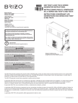
10. Install the PDS
WARNING: Risk of electrocution. Disconnect the electricity
to the working area at the main breaker panel before
performing the installation steps for hardwiring.
The PDS is designed to fit within a service closet or 2x6 stud
cavity with access panel. The service closet or access panel must
be located less than 30’ (9.14 m) from the overhead rain panel.
Recommended maximum distance is 25’ (7.62 m).
If mounting boards are required, they should be positioned to
allow adequate surface area to attach the PDS via the existing
mounting holes on both ends of the PDS box.
Route electrical wire to the service closet or 2x6 stud framing,
within 24″ (610 mm) of the PDS. Make sure the wire is in a
position to reach the PDS where electrical connections can be
made, and allow enough wire to create a drip loop.
Orient the PDS box within the service closet or access panel to
allow room for cover removal and connecting the cables. If
possible, connect the cables through the side holes rather than
those on the cover to avoid complicated cover removal for
servicing.
100-240 VAC
6" (152 mm) Min
2x6 Stud Cavity
8-1/4" (210 mm)
Mounting Board
Power Data Supply
Position
to far left.
2x6
Drip Loop
Kohler Co. 17 1207716-2-C

Install the PDS (cont.)
If installing the PDS within a 2x6 stud cavity, position it to the far
left of the cavity to allow room for connecting the cables to the
side holes.
Attach the PDS to structural framing or other secure surface using
standard wood or drywall screws (not supplied). Mounting
boards may need to be installed between stud framing.
Remove the PDS cover.
Feed electrical wire through the 1/2″ NPT hole into the power
connection chamber of the PDS.
Using wire nuts, connect the Line (black or brown), Neutral
(white or blue with white), and Ground (green or green with
yellow stripe) wires. Refer to the ″PDS Connection Key″
illustration.
Following the electrical codes for internal wire bending, carefully
tuck the wires into the PDS housing. Ensure the wires will not be
pinched when reinstalling the PDS cover.
1207716-2-C 18 Kohler Co.

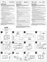
PDS Connection Key
Status
LED
Ground: Green
or Green with
Yellow Stripe
Chroma Power Cable
30' (9.14 m)
Chroma Data Cable
Connect power
cord conductors
with wire nuts.
Neutral: White or Blue with White
Line: Black or Brown
Fuse
100-240 VAC
1/2" NPT
RS485 Chain
(CSM, Steam Generator)
To Rain Panel
30' (9.14 m)
Kohler Co. 19 1207716-2-C

11. Connect the Cables
WARNING: Risk of electric shock. Make sure the power
cord is unplugged before removing the access cover.
IMPORTANT! When possible, connect the cables through the side
holes of the PDS rather than the cover holes to ease cover removal
for servicing.
Prepare cable ends for installation into the PDS by unthreading
the strain relief cap and separating the rubber stopper from the
threaded body. This will prevent the cables from twisting while
the strain relief is threaded into the box.
Insert the chroma power cable into a 1/2” NPT hole and install
into the “RAIN PANEL” connector until it snaps together.
Insert the chroma data cable into a 1/2” NPT hole and install into
the “DATA IN” connector until it snaps together.
Secure the cables and the electrical wire to the PDS using the
watertight strain relief fittings. Thread the fitting into the box,
then slide the rubber stopper into the fitting. Tighten the cap to
create a seal.
Access Cover
Fuse
Chroma Data Cable
100-240 VAC
Chroma
Power Cable
Strain Relief Fitting
Cap
PDS
1207716-2-C 20 Kohler Co.
/