LG 55LV77A Installation guide

Type
Installation guide
www.lg.com
P/NO : MFL68606101 (1806-REV03)
Copyright © 2018 LG Electronics Inc. All Rights Reserved.
*MFL68606101*
Easy Setup Guide
LG Digital
Signage
(MONITOR SIGNAGE)
Please read this manual carefully before operating your set and retain it for
future reference.
55LV75A
55LV77A
2
ASSEMBLING AND PREPARING
ENG
ENGLISH
ASSEMBLING AND PREPARING
Accessories
Check your product box for the following items. If there are any missing accessories, contact the local
dealer where you purchased your product. The illustrations in this manual may differ from the actual product
and accessories.
Do not use any pirated items to ensure the safety and product life span.
Any damages or injuries by using pirated items are not covered by the warranty.
CAUTION
Remote Control
and Batteries
Power Cord IR Receiver RS-232C Cable
DP Cable
M4 x L6
Screws (8 ea)
M6 x L10
Screws (4 ea)
CD (Owner's Manual) /
Cards
Mounting Cable Tie (2 ea)
(For Cable Arrangement)
Tiling Guide(4 ea)
The accessories supplied with your product may vary depending on the model.
Product specifications or contents in this manual may be changed without prior notice due to upgrade
of product functions.
SuperSign SW & Manual
- Downloading from the LG Electronics website.
- Visit the LG Electronics website (
http://partner.lge.com
) and download the latest software for your
model.
NOTE
3
ASSEMBLING AND PREPARING
ENG
ENGLISH
Dimensions (Width x Height x Depth) / Weight
To View the Owners Manual
Insert CD-ROM in Computer.
CD-ROM will open automatically.(for Windows only)
If it does not run automatically, it is available to see the below sequence.
My computer
Digital_LG(CD-ROM)
Index.htm Open
My computer
Digital_LG(CD-ROM)
Manual
Owner's Manual Open
H
W
D
1213.4 mm x 684.2 mm x 88.5 mm / 23 kg
4
ASSEMBLING AND PREPARING
ENG
ENGLISH
Do not Clamp
Do not drop from clamping.
2 Persons needed for transport
Load with care.
PRECAUTION IN MOVEMENT
Adhere to the warning signs printed on the Box.
Do not drop from stacking.
4 Persons needed for transport
Do not transport horizontally.
Do not drop from carrying.
This way up/ Fragile/ Keep away from rain/ Stacking limit 4.
Do not tumble the Set box sideward down.
Do not place the product on the top of a box.
Do not lean on the product.
- The illustration may look different from the actual product.
5
ASSEMBLING AND PREPARING
ENG
ENGLISH
Move the Set as a team of 2 persons. When you move
the bare Set, please use one hand on grabbing the
handle and the other support under the Set.
PRECAUTION IN HANDLING Precaution
10 cm
10 cm
10 cm10 cm
20 cm
1 Remove the L-bracket on the corner of the Set be-
fore installation. When moving the Set, re-assemble
the L-bracket.
2 Be careful not to collide the sets with the floor or with
each other. Install in the space with enough airflow.
6
ASSEMBLING AND PREPARING
ENG
ENGLISH
Causes & Phenomena of the
Line Defect
The line defect would occur on your Set if you strike on
the edge of the Set.
LOG (LINE ON GLASS) DEFECT
COF (CHIP ON FILM) DEFECT
COF Cable
Source PCB
COF Cable
Source PCB
1 Shock on Module Top Side Top COF Crack
Vertical Line Defect
2 Shock on Module Left Side Left COF Crack
Horizontal Line Defect
1 Shock on Module Left/Top Corner Left/Top LOG
Crack Horizontal Line Defect
7
ASSEMBLING AND PREPARING
ENG
ENGLISH
Installing the Product
1 Cut Packing Strap of the Box.
3 Open the Box and remove the top packing.
5 Open the Poly Bag.
4 Remove the Upper Box.
6 Undress the Poly Bag.
2 Cut Tape on the Box.
- The illustration may look different from the actual product.
8
ASSEMBLING AND PREPARING
ENG
ENGLISH
7 Lift up the Set using the SIDE/BACK Handle.
9 With one hand under the set and the other hand grabbing the set, move the set.
10 Lay the back of the Set down on the table.
8 Remove Bottom packing when lifting up the Set.
9
ASSEMBLING AND PREPARING
ENG
ENGLISH
11 Use the cushion or Pad when you lay the face of the Set downward.
12 Connect IR receiver to use remocon. And then, connect power cord.
1
2
10
ASSEMBLING AND PREPARING
ENG
ENGLISH
How to Mount the Set
Tiling Displays
Example of 2 x 2 tiling
How to Join Sets
The load applied to each set should be
supported by the wall mount plate or the wall
using a VESA wall mount (600 x 400).
The load applied to each set should be
supported by the wall mount plate using a
VESA wall mount. (Each set must be firmly
mounted to the wall mount plate or the wall.)
You may mount the set without using
the tiling guide; this does not affect the
performance of the device.
Loosen the screws on the set to install the
tiling guides. (The screws are enclosed with
the other components in the box, including
the tiling guides.)
NOTE
Set 4 joined to the rest of the sets
(2 x 2 tiling)
1 Join other sets using screws for fixing the
VESA wall mount in the same way as above.
2 After joining the sets, use the tiling guide to
adjust the gap between the sets.
3 Now the 2 x 2 tiling is complete. You can tile in
various combinations, such as 3 x 3.
When you connect Monitor sets for
multivision, you may find that the screen
color is not the same across all the Monitor
sets. If you want to adjust the screen color
manually, please refer to the Installation
Manual.
When you install multiple Monitor sets onto a
wall, attach the IR Receiver to all the sets, or
use an RS-232C cable to connect them and
then attach the IR Receiver to the first set.
CAUTION
Screws for attaching the
VESA wall mount (M6)
600
400
≤ 6 mm
Screws (15-M4)
11
REMOTE CONTROL
ENG
ENGLISH
REMOTE CONTROL
The descriptions in this manual are based on the buttons of the remote control. Please
read this manual carefully and use the Monitor set correctly.
To replace batteries, open the battery cover, replace
batteries (1.5 V AAA) matching and ends to the
label inside the compartment, and close the battery
cover. To remove the batteries, perform the installation
actions in reverse.
ID
BACK
TILE
ON
OFF
EXIT
(POWER)
Turns the monitor set on or off.
MONITOR ON
Turn on the monitor.
MONITOR OFF
Turn off the monitor.
1/a/A Button
Toggles between numerical
and alphabetical.
ENERGY SAVING( )
Reduces power consumption
by adjusting peak screen
brightness.
INPUT
Selects the input mode.
3D
This button does not apply to
this model.
Number and Alphabet Buttons
Enters numerical or alphabetical
characters depending on the
setting.
CLEAR
Deletes the entered numerical
or alphabetical character.
PSM
Selects the Picture Status
Mode.
MUTE
Mutes all sounds.
ARC
Selects the Aspect Ratio
Mode.
Volume Up / Down
This button does not apply to
this model.
BRIGHTNESS Key
Adjust the brightness by
pressing the Up and Down
buttons on the remote control.
In USB mode, the OSD menu
has the Page function to move
to the next file list.
Do not mix old and new batteries, as this
may damage the remote control.
Make sure to point the remote control to the
remote control sensor on the monitor set.
CAUTION
12
REMOTE CONTROL
ENG
ENGLISH
Select an input signal.
AV Component RGB HDMI DVI-D
Dispaly Port USB
NOTE
W.BAL
Enters the White Balance
menu.
Navigation Buttons
Scrolls through menus or
options.
S.MENU
(SuperSign Menu Key)
This button does not apply to
this model.
EXIT
Clears all on-screen displays
and returns to Monitor set
viewing from any menu.
TILE
Selects the TILE Mode.
INFO
Displays the input
information.
SETTINGS
Accesses the main menus
or saves your input and exit
menus.
OK
Selects menus or options and
confirms your input.
BACK
Allows the user to move back
one step in user interaction
function.
Allows you to control various
multimedia devices simply
by using the remote control
through the SimpLink menu.
(It may not be supported
depending on the model.)
USB Menu control buttons
Controls media playback.
ID ON/OFF
When the number of Picture
ID is equal to Set ID you can
control the monitor which
you want in the multi display
condition.
AUTO
Automatically adjusts picture
position and minimizes image
instability.(RGB input only)
13
MAKING CONNECTIONS
ENG
ENGLISH
VIDEO OUT
AUDIO IN
MAKING CONNECTIONS
Connect the signal input cable
and tighten it by turning the
screws clockwise.
NOTE
14
MAKING CONNECTIONS
ENG
ENGLISH
Connecting the Power Cord
Connecting the External devices
Power Button
1
2
HDMI
DVI
AV
Component
AV
Component
HDMI
DVI
RGB
LAN
Display Port
HDMI
DVI
AV
Component
HDMI
DVI
AV
Component
HDMI
AV
Component
HD Receiver DVD VCR
Memory storage
PC Camcorder/ Camera Gaming device
Speaker
USB
15
MAKING CONNECTIONS
ENG
ENGLISH
Daisy Chain Monitors
Monitor 1 Monitor 2 Monitor 3 Monitor 4
DP Cable
Use the cable provided with the product or use a DisplayPort certified cable version 1.1a or higher.
16
MULTIVISION CONFIGURATION
ENG
ENGLISH
MULTIVISION CONFIGURATION
1
IR Receiver connection.
3
Set ID setup for each set. (* The model
55LV75A does not support any functions for
controlling the Fan.)
2
Connecting the Power cord.
4
IR Receiver removal for all sets except for Set 1.
5
RGB connection.
Function Setting
Back of the product.
1
2
Macintosh Adapter
(not included)
Back of the product.
PC/ MAC
15-pin D-Sub Signal
Cable (Max 3m)
(not included)
Move OK
OPTION
• Language
• ISM Method : Normal
• DPM Select : 5 sec.
• Fail Over : Off
• Factory Reset
• Set ID : 1
• Tile Mode
• PIP/PBP
• Fan
• USB Content Recovery : Off
• SIMPLINK
• Product/Service Info.
1
Close
17
MULTIVISION CONFIGURATION
ENG
ENGLISH
6
Connect the Monitor sets, in series, using an RS-232C cable.
7
Installation Menu setup.
8
Tile Mode setup. (* The model 55LV75A does not support any functions for controlling the Fan.)
Monitor 1 Monitor 2 Monitor 3 Monitor 4
RS-232C Cable
Installation Menu (V 2.21)
LG Digital Signage Setup
White Balance Adjust
Password Change
Conguration Cloning
Set ID Setup
OK
Move OK
OPTION
• Language
• ISM Method : Normal
• DPM Select : 5 sec.
• Fail Over : Off
• Factory Reset
• Set ID : 1
• Tile Mode
• PIP/PBP
• Fan
• USB Content Recovery : Off
• SIMPLINK
• Product/Service Info.
Move Prev.
Tile
Tile Mode
Auto Config.
Position
Size
Natural
Reset
Off
2
2
1
Tile Mode
Row
Colunm
Tile ID
18
MULTIVISION CONFIGURATION
ENG
ENGLISH
In Tile Mode you can view an image in a larger
scale by connecting multiple monitors.
Tile Mode Off:
An input image is not
enlarged, and the same image is shown on
all connected monitors.
Tile Mode On:
An input image is enlarged
according to the value in the H. Set Count
and V. Set Count fields.
(* The model 55LV75A does not support any
functions for controlling the Fan.)
Setting the Tile Mode
ID 1
ID 2
ID 3
ID 4
2X2
When using 4 monitors
ID 1
ID 2
ID 4
ID 5
ID 3
ID 6
ID 7
ID 8
ID 9
3X3
When using 9 monitors
ID 1
ID 2
ID 5
ID 6
ID 3
ID 7
ID 9
ID 10
ID 11
ID 4
ID 8
ID 12
ID 13
ID 14
ID 15
ID 16
4X4
When using 16 monitors
ID 1
ID 2
1X2
When using 2 monitors
Tile ID
Move
OK
OPTION
• Language
• ISM Method : Normal
• DPM Select : 5 sec.
• Fail Over : Off
• Factory Reset
• Set ID : 1
• Tile Mode
• PIP/PBP
• Fan
• USB Content Recovery : Off
• SIMPLINK
• Product/Service Info.
Move Prev.
Tile
Tile Mode
Auto Config.
Position
Size
Natural
Reset
Off
2
2
1
Tile Mode
Row
Colunm
Tile ID
19
MULTIVISION CONFIGURATION
ENG
ENGLISH
AUDIO
(RGB/DVI)
REMOTE
CONTROL IN
RS-232C OUT
RS-232C IN
RS-232C OUT
RS-232C IN
RS-232C OUT
RS-232C IN
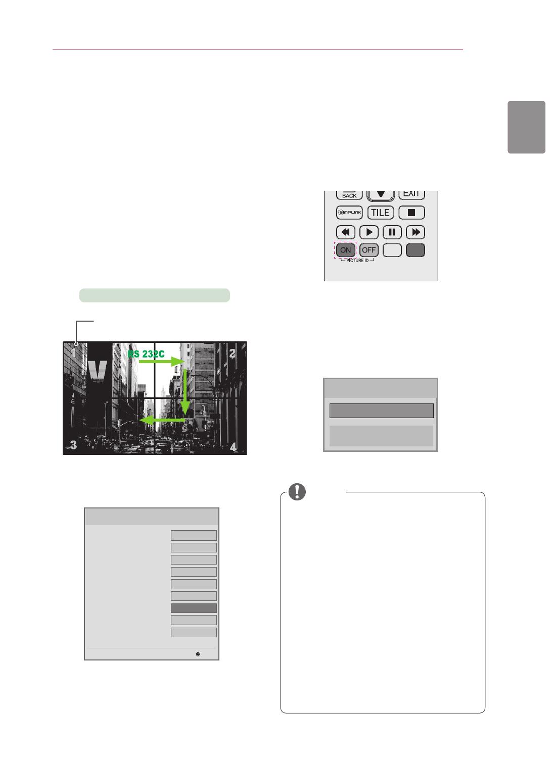
The Picture ID menu allows you to control all sets using the IR Receiver connected to Set 1.
The IR signal of the remote control is
transmitted through the RS-232C cables
connected in serial mode.
When you set a Picture ID using the remote
control, you can only control the Set that
matches the Picture ID.
ex) For example, if you set a Picture ID to 2,
you can only control the monitor with the
Set ID 2.
If Picture ID is set to Off, you can control all
monitors at the same time.
Setting the Picture ID
IR Receiver
2X2 Multi-Vision (Total Set ID: 4)
Sets the total number of products to be connected in
Tile mode. Total Set ID is used as the maximum value of
Picture ID.
1
Set the Total Set ID in the Installation Menu.
2
Press the red ON button on the remote control
to assign the Picture ID.
3
If you press the left/right buttons or press the
ON button repeatedly, the Picture ID cycles
through OFF/1 and the value set in the Total Set
ID.
For example, if the Picture ID is assigned to
2, the upper right display (Set ID: 2) can be
controlled by IR signals.
For each set, you can change the settings
for the PICTURE, AUDIO, TIME, NETWORK
and MY MEDIA menus or the hot keys on the
remote control.
If you press the green OFF button for Picture
IDs, the Picture IDs for all sets are turned off.
If you then press any button on the remote
control, all sets will start working again.
Picture ID will be disabled while using the
MY MEDIA menu.
If Picture ID is set to Off, holding buttons
on the remote control will execute only one
action at a time.
NOTE
Picture ID
Close
Off
LG Digital Signage Setup (V2.21)
255
On
9600
0
On
On
On
On
OK
• Factory Reset
• Menu Display
• OSD Display
• LG IR Operation
• Local Key Operation
• Input Source Change
• Total Set ID
• Baudrate
• Min Volume
Off
  • Page 1 1
  • Page 2 2
  • Page 3 3
  • Page 4 4
  • Page 5 5
  • Page 6 6
  • Page 7 7
  • Page 8 8
  • Page 9 9
  • Page 10 10
  • Page 11 11
  • Page 12 12
  • Page 13 13
  • Page 14 14
  • Page 15 15
  • Page 16 16
  • Page 17 17
  • Page 18 18
  • Page 19 19
  • Page 20 20

LG 55LV77A Installation guide

Type
Installation guide

Ask a question and I''ll find the answer in the document

Finding information in a document is now easier with AI