Page is loading ...

IMR02L03-E1
PF900
PF901
Instruction
Manual
Ramp/Soak Controller
This document contains 530 pages.
Use caution before printing out the
contents.
(This comment is not displayed in a
hardcopy.)

All Rights Reserved, Copyright © 2010, RKC INSTRUMENT INC.
NOTICE
Windows is a trademark of Microsoft Corporation.
Modbus is a registered trademark of Schneider Electric.
Company names and product names used in this manual are the trademarks or registered trademarks
of the respective companies.
This manual assumes that the reader has a fundamental knowledge of the principles of
electricity, process control, computer technology and communications.
The figures, diagrams and numeric values used in this manual are only for purpose of
illustration.
RKC is not responsible for any damage or injury that is caused as a result of using this
instrument, instrument failure or indirect damage.
RKC is not responsible for any damage and/or injury resulting from the use of instruments
made by imitating this instrument.
Periodic maintenance is required for safe and proper operation of this instrument. Some
components have a limited service life, or characteristics that change over time.
Every effort has been made to ensure accuracy of all information contained herein. RKC
makes no warranty expressed or implied, with respect to the accuracy of the information.
The information in this manual is subject to change without prior notice.
No portion of this document may be reprinted, modified, copied, transmitted, digitized, stored,
processed or retrieved through any mechanical, electronic, optical or other means without
prior written approval from RKC.

IMR02L03-E1
i-1
Safety Precautions
Pictorial Symbols (safety symbols)
Various pictorial symbols are used in this manual to ensure safe use of the product, to protect you and
other people from harm, and to prevent damage to property. The symbols are described below.
Be sure you thoroughly understand the meaning of the symbols before reading this manual.
: This mark indicates precautions that must
be taken if there is danger of electric shock,
fire, etc., which could result in loss of life or
injury.
:
This mark indicates that if these precautions
and operating procedures are not taken,
damage to the instrument may result.
: This mark indicates that all precautions
should be taken for safe usage.
An external protection device must be installed if failure of this instrument
could result in damage to the instrument, equipment or injury to personnel.
All wiring must be completed before power is turned on to prevent electric
shock, fire or damage to instrument and equipment.
This instrument must be used in accordance with the specifications to
prevent fire or damage to instrument and equipment.
This instrument is not intended for use in locations subject to flammable or
explosive gases.
Do not touch high-voltage connections such as power supply terminals, etc.
to avoid electric shock.
RKC is not responsible if this instrument is repaired, modified or
disassembled by other than factory-approved personnel. Malfunction can
occur and warranty is void under these conditions.

IMR02L03-E1
i-2
This product is intended for use with industrial machines, test and measuring equipment.
(It is not designed for use with medical equipment and nuclear energy.)
This is a Class A instrument. In a domestic environment, this instrument may cause radio
interference, in which case the user may be required to take additional measures.
This instrument is protected from electric shock by reinforced insulation. Provide reinforced
insulation between the wire for the input signal and the wires for instrument power supply,
source of power and loads.
Be sure to provide an appropriate surge control circuit respectively for the following:
- If input/output or signal lines within the building are longer than 30 meters.
- If input/output or signal lines leave the building, regardless the length.
This instrument is designed for installation in an enclosed instrumentation panel. All
high-voltage connections such as power supply terminals must be enclosed in the
instrumentation panel to avoid electric shock by operating personnel.
All precautions described in this manual should be taken to avoid damage to the instrument
or equipment.
All wiring must be in accordance with local codes and regulations.
All wiring must be completed before power is turned on to prevent electric shock, instrument
failure, or incorrect action.
The power must be turned off before repairing work for input break and output failure
including replacement of sensor, contactor or SSR, and all wiring must be completed before
power is turned on again.
To prevent instrument damage or failure, protect the power line and the input/output lines
from high currents with a protection device such as fuse, circuit breaker, etc.
Prevent metal fragments or lead wire scraps from falling inside instrument case to avoid
electric shock, fire or malfunction.
Tighten each terminal screw to the specified torque found in the manual to avoid electric
shock, fire or malfunction.
For proper operation of this instrument, provide adequate ventilation for heat dispensation.
Do not connect wires to unused terminals as this will interfere with proper operation of the
instrument.
Turn off the power supply before cleaning the instrument.
Do not use a volatile solvent such as paint thinner to clean the instrument. Deformation or
discoloration will occur. Use a soft, dry cloth to remove stains from the instrument.
To avoid damage to instrument display, do not rub with an abrasive material or push front
panel with a hard object.
Do not connect modular connectors to telephone line.
When high alarm with hold action is used for Event function, alarm does not turn on while
hold action is in operation. Take measures to prevent overheating which may occur if the
control device fails.

IMR02L03-E1
i-3
Symbols
Pictorial Symbols (safety symbols)
: This mark indicates important information on installation,
handling and operating procedures.
: This mark indicates supplemental information on installation,
handling and operating procedures.
: This mark indicates where additional information may be located.
Character Symbols
This manual indicates 11-segment display characters as shown below.
0 1 2 3 4 5 6 7 8 9 Minus Period
0 1 2 3 4 5 6 7 8 9 - .
A B (b) C c D (d) E F G H I J K
A b C c D E F G H I J K
L M N (n) O (o) P Q q R r S T t
L M n o P Q q R r S T t
U u V W X Y Z Dash /
*
Temperature units
U u V W X Y Z ` / Š $ &
%
→
_
% ‹ _
8.
Dim lighting
8.
Flashing
8
Bright lighting
Abbreviation Symbols
The names of some items are indicated by alphabetical abbreviations in this manual.
Abbreviation
symbols
Name
Abbreviation
symbols
Name
PV Measured value DI (1 to 6) Digital input (1 to 6)
SV Set value DO (1 to 12) Digital output (1 to 12)
AT Autotuning FBR Feedback resistance
ST Self-tuning
OUT (1 to 3) Output (1 to 3)
HBA (1 or 2) Heater break alarm (1or 2)
CT (1 or 2) Current transformer (1 or 2)
LBA Control loop break alarm
LBD LBA deadband

IMR02L03-E1
i-4
Document Configuration
There are four manuals pertaining to this product. Please be sure to read all manuals specific
to your application requirements. If you do not have a necessary manual, please contact
RKC sales office, the agent, or download from the official RKC website.
The following manuals can be download from the official RKC website:
http://www.rkcinst.com/english/manual_load.htm.
Manual Manual Number Description Remarks
PF900/PF901
User’s Manual
IMR02L04-E
This document describes installation,
wiring and basic operation.
Provided with
product
PF900/PF901
Instruction Manual
IMR02L03-E1
This Manual.
This manual explains the method of
the mounting and wiring, the
operation of various functions, and
troubleshooting.
PF900/PF901 Pattern
Record Sheet
IMR02L05-E
This spreadsheet is to record patterns
for Program control operation.
Communication Setup
Tool for PF900/PF901
Program Controller
(WinUCI-PF900)
Instruction Manual
IMT01D09-E
This document describes installation
of communication setup tool,
connection and setting of data.
Provided with
product
On CD-ROM
[Downloadable]

IMR02L03-E1
i-5
Contents
Page
NOTICE
Safety Precautions................................................................................................................i-1
Pictorial Symbols (safety symbols)...............................................................................i-1
WARNING ........................................................................................................................i-1
CAUTION..........................................................................................................................i-2
Symbols.................................................................................................................................i-3
Pictorial Symbols (safety symbols)...............................................................................i-3
Character Symbols .......................................................................................................i-3
Abbreviation Symbols ...................................................................................................i-4
Document Configuration........................................................................................................i-5
1. OUTLINE............................................................................1-1
The chapter 1 describes features, package contents and model code, etc.
1.1 Features .......................................................................................................1-2
1.2 Checking the Product ...................................................................................1-4
1.3 Model Code..................................................................................................1-5
Suffix code................................................................................................................1-5
Quick start code 2 (Initial setting code).....................................................................1-9
1.4 Parts Description........................................................................................1-12
Front Panel View....................................................................................................1-12
Key operation.........................................................................................................1-15
Side view................................................................................................................1-16
1.5 Input/Output and Function Blocks...............................................................1-17
1.6 Handling Procedure to Operation...............................................................1-18
2. MOUNTING........................................................................2-1
The chapter 2 describes installation environment, mounting cautions, dimensions and
mounting procedures.
2.1 Mounting Environment..................................................................................2-2
2.2 Mounting Cautions........................................................................................2-3
2.3 Dimensions...................................................................................................2-5
2.4 Procedures of Mounting and Removing .......................................................2-6
Mounting procedures................................................................................................2-6
Removal procedures ................................................................................................2-7
Removal procedures by using slotted (standard) screwdriver..................................2-8

IMR02L03-E1
i-6
Page
3. WIRING..............................................................................3-1
The chapter 3 describes wiring cautions, wiring layout and wiring of terminals.
3.1 Wiring Cautions............................................................................................3-2
Power supply wiring..................................................................................................3-2
Input/Output wiring ...................................................................................................3-3
Ground wiring...........................................................................................................3-4
Wiring method..........................................................................................................3-4
3.2 Terminal Layout............................................................................................3-6
Terminal configuration..............................................................................................3-6
Isolations of the instrument.......................................................................................3-7
3.3 Wiring of Each Terminal...............................................................................3-8
Power supply............................................................................................................3-8
Measured input (TC/RTD/Voltage/Current) [universal input]....................................3-9
Output 1 (OUT1)/Output 2 (OUT2).........................................................................3-10
Output 3 (OUT3).....................................................................................................3-12
Digital input 1 to 11 (DI1 to DI6 [optional], DI7 to DI11 [standard]).........................3-13
Digital output 1 to 4 (DO1 to DO4) [standard].........................................................3-14
Digital output 5 to 12 (DO5 to DO12) [optional]......................................................3-15
Current transformer (CT) input/Feedback resistance (FBR) input [optional]...........3-16
Communication 1/Communication 2 [optional].......................................................3-17
3.4 Handling of the Terminal Cover [optional] ..................................................3-18
Mounting procedures..............................................................................................3-18
Removing procedures ............................................................................................3-19
4. BASIC OPERATION..........................................................4-1
The chapter 4 describes mode type, parameter, mode switching and set value
change/setting.
4.1 Operation Menu............................................................................................4-2
4.1.1 Mode switching.......................................................................................................4-2
4.1.2 Input type and input range display..........................................................................4-3
4.2 Changing Set Value......................................................................................4-4
Numeric value setting...............................................................................................4-4
Setting item selection ...............................................................................................4-6
4.3 Operation of the Direct Keys.........................................................................4-7
Direct key menu .......................................................................................................4-7
Direct key type..........................................................................................................4-8
4.4 Protecting Setting Data.................................................................................4-9
4.5 Parameter Description................................................................................4-10
4.5.1 SV setting & monitor mode ...................................................................................4-10
SV setting mode.....................................................................................................4-10
Monitor mode .........................................................................................................4-13
4.5.2 Operation mode ....................................................................................................4-15
Parameter list.........................................................................................................4-15
Parameter switching...............................................................................................4-16

IMR02L03-E1
i-7
Page
4.5.3 Parameter setting mode........................................................................................4-17
Setting type for Program pattern ............................................................................4-17
Parameter list [Partial setting type].........................................................................4-18
Parameter switching [Partial setting type]...............................................................4-23
Parameter list [Batch setting type]..........................................................................4-27
Parameter switching [Batch setting type]................................................................4-28
4.5.4 Setup setting mode...............................................................................................4-30
Parameter list.........................................................................................................4-30
Parameter switching...............................................................................................4-32
4.5.5 Engineering mode.................................................................................................4-33
Parameter list.........................................................................................................4-33
Parameter switching...............................................................................................4-45
4.5.6 Initial level engineering mode................................................................................4-51
Parameter list.........................................................................................................4-51
Parameter switching...............................................................................................4-54
5. OPERATION......................................................................5-1
The chapter 5 describes initial setting before operation, cautions for operation, parameter
setting by Operation mode and setting procedure via loader communication.
5.1 Initial Setting.................................................................................................5-2
5.1.1 Check the parameter related to the input................................................................5-2
5.1.2 Check the parameter related to the event action ....................................................5-4
5.1.3 Check the parameter related to the control.............................................................5-5
5.1.4 Check set value of parameter for program control operation..................................5-7
5.2 Operating Precautions..................................................................................5-8
5.3 Type and Switching Procedures of Operation Mode ....................................5-9
5.3.1 Type of Operation mode .........................................................................................5-9
5.3.2 Operation mode switching.......................................................................................5-9
5.4 Program Control Operation.........................................................................5-12
5.4.1 Program control mode display ..............................................................................5-12
5.4.2 Program control operation procedures..................................................................5-13
5.4.3 Set up program patterns .......................................................................................5-13
5.4.4 Start/End Program control.....................................................................................5-21
5.4.5 Changing procedure of End segment number in Program pattern........................5-23
5.5 Fixed Set Point Control Operation..............................................................5-24
5.5.1 Fixed set point control mode display.....................................................................5-24
5.5.2 Switch to Fixed set point control mode..................................................................5-25
5.5.3 Parameter setting via Fixed set point control mode ..............................................5-26
5.6 Manual Control Operation...........................................................................5-28
5.6.1 Manual control mode display ................................................................................5-28
5.6.2 Switch to Manual control mode.............................................................................5-29
5.6.3 Parameter setting via Manual control mode..........................................................5-30
5.7 Parameter Setting via Loader Communication...........................................5-33
5.7.1 Preparation ...........................................................................................................5-33
5.7.2 Instructions for use................................................................................................5-33
5.7.3 Connections for loader communication.................................................................5-34
5.7.4 Parameter setting..................................................................................................5-35

IMR02L03-E1
i-8
Page
6. FUNCTION AND SETTING PROCEDURE .......................6-1
The chapter 6 describes function and parameter switching procedures.
6.1 Input .............................................................................................................6-2
6.1.1 Changing Measured value (PV)..............................................................................6-2
6.1.2 Changing Sampling cycle........................................................................................6-5
6.1.3 Changing Measured value (PV) unit display...........................................................6-6
6.1.4 Changing Power supply frequency .........................................................................6-7
6.1.5 Input correction.......................................................................................................6-8
6.1.6 Input filter..............................................................................................................6-10
6.1.7 Square root extraction...........................................................................................6-11
6.1.8 Feedback resistance (FBR) input..........................................................................6-13
6.1.9 Digital input (DI)....................................................................................................6-14
6.1.10 Action, Function and Settings for Input error.......................................................6-31
6.1.11 Current transformer (CT) input setting and assignment......................................6-34
6.1.12 Setting limiter......................................................................................................6-36
6.2 Output.........................................................................................................6-37
6.2.1 Output assignment (OUT1 to OUT3).....................................................................6-37
6.2.2 Digital output (DO) assignment (DO1 to DO12)....................................................6-41
6.2.3 Setting of Energized/De-energized (OUT2, OUT3 or DO1 to DO12)....................6-43
6.2.4 Output limiter.........................................................................................................6-45
6.2.5 Proportional cycle time (OUT1 to OUT3) ..............................................................6-47
6.2.6 Transmission output..............................................................................................6-49
6.3 Display........................................................................................................6-54
6.3.1 Graph display selection.........................................................................................6-54
6.3.2 Setting of Power saving mode ..............................................................................6-59
6.4 Event 1 to 4, Heater Break Alarm (HBA)
and Control Loop Break Alarm (LBA).........................................................6-61
6.4.1 Setting procedure of Event 1 to 4..........................................................................6-61
6.4.2 Setting procedure of Heater break alarm (HBA) ...................................................6-77
6.4.3 Setting procedure of Control loop break alarm (LBA) ...........................................6-81
6.4.4 Interlock release....................................................................................................6-86
6.5 Control........................................................................................................6-88
6.5.1 Change Control Action..........................................................................................6-88
6.5.2 Control response parameter ...............................................................................6-100
6.5.3 Position proportioning PID control setting...........................................................6-102
6.5.4 Manual reset.......................................................................................................6-113
6.5.5 Start action at recovering power failure...............................................................6-115
6.5.6 Ramp/Soak stabilizer function.............................................................................6-117
6.5.7 Autotuning (AT)...................................................................................................6-119
6.5.8 Autotuning (AT) with learning..............................................................................6-130
6.5.9 Level PID ............................................................................................................6-135

IMR02L03-E1
i-9
6.6 Program Control.......................................................................................6-143
Program configuration..........................................................................................6-143
6.6.1 Memory group.....................................................................................................6-144
Memory group to be set by segment....................................................................6-144
Memory group to be set by pattern.......................................................................6-144
Setting example of Memory group........................................................................6-145
Setting procedure.................................................................................................6-146
6.6.2 Program control start selection ...........................................................................6-148
Start with the Set value (SV) in the Reset mode..........................................................6-148
PV start 1 [Time fixed type] ..................................................................................6-148
PV start 2 [Time saving & ramp holding type] (Factory set value)........................6-149
PV start 3/PV start 4 [Time saving & level searching type]...................................6-151
Parameter setting.................................................................................................6-152
Setting procedure.................................................................................................6-152
6.6.3 Search function...................................................................................................6-154
Description of function..........................................................................................6-154
Parameter setting.................................................................................................6-155
Setting procedure.................................................................................................6-155
6.6.4 Hold (HOLD).......................................................................................................6-156
HOLD display.......................................................................................................6-156
Key operation.......................................................................................................6-156
6.6.5 Step (STEP)........................................................................................................6-157
Key operation.......................................................................................................6-157
6.6.6 Wait.....................................................................................................................6-158
Description of function..........................................................................................6-158
Parameter setting.................................................................................................6-161
Setting procedure.................................................................................................6-163
6.6.7 Repeat and Pattern link.......................................................................................6-164
Description of function..........................................................................................6-164
Parameter setting.................................................................................................6-166
Setting procedure.................................................................................................6-167
6.6.8 Pattern end .........................................................................................................6-169
Description of function..........................................................................................6-169
Parameter setting.................................................................................................6-171
Setting procedure.................................................................................................6-172
6.6.9 Time signal (Segment signal)..............................................................................6-174
Description of function..........................................................................................6-174
Setting procedure flowchart..................................................................................6-178
Parameter setting.................................................................................................6-179
Setting procedure.................................................................................................6-181
6.6.10 Output program.................................................................................................6-184
Parameter setting.................................................................................................6-185
Setting procedure.................................................................................................6-186
6.6.11 Edit function......................................................................................................6-187
Pattern copy.........................................................................................................6-187
Segment copy ......................................................................................................6-187
Data clear.............................................................................................................6-187
Parameter setting.................................................................................................6-187
Setting procedure.................................................................................................6-188
6.6.12 Tag function......................................................................................................6-191
6.6.13 Forward/Back-up function.................................................................................6-192

IMR02L03-E1
i-10
Page
6.7 Intercontroller Communication Function...................................................6-193
Settable parameter in link operation.....................................................................6-194
6.7.1 Operation procedure...........................................................................................6-195
6.7.2 Wiring procedure for Intercontroller communication............................................6-196
Connectable controller..........................................................................................6-196
Communication terminal number and signal details.............................................6-197
Wiring example.....................................................................................................6-197
6.7.3 Parameter setting for master controller...............................................................6-199
Parameter setting at F61 in the Engineering mode..............................................6-199
Parameter setting at F61 in the Initial level engineering mode.............................6-200
Parameter setting at Wait memory group setting block
in the Parameter setting mode. ............................................................................6-202
Setting procedure.................................................................................................6-202
6.7.4 Parameter setting for slave controller..................................................................6-204
6.7.5 Action at power ON.............................................................................................6-206
6.7.6 Link operation via intercontroller communication................................................6-207
When intercontroller communication is in error state............................................6-207
Autotuning (AT) in intercontroller communication.................................................6-208
Wait function in intercontroller communication.....................................................6-208
Remarks...............................................................................................................6-209
7. HOST COMMUNICATION [OPTIONAL]...........................7-1
The chapter 7 describes Host communication including connection, setting, protocol and
communication data.
7.1 Connections..................................................................................................7-2
7.1.1 RS-232C connection...............................................................................................7-2
7.1.2 RS-422A connection...............................................................................................7-5
7.1.3 RS-485 connection .................................................................................................7-6
7.1.4 USB connection......................................................................................................7-7
7.2 Setting..........................................................................................................7-9
7.2.1 Description of each parameter................................................................................7-9
7.2.2 Setting procedure..................................................................................................7-10
7.2.3 Communication requirements...............................................................................7-11
7.3 RKC Communication Protocol....................................................................7-13
7.3.1 Polling...................................................................................................................7-13
7.3.2 Selecting...............................................................................................................7-20
7.4 Modbus Protocol.........................................................................................7-25
7.4.1 Message format....................................................................................................7-25
7.4.2 Function code .......................................................................................................7-26
7.4.3 Communication mode...........................................................................................7-26
7.4.4 Slave responses ...................................................................................................7-27
7.4.5 Calculating CRC-16 ..............................................................................................7-28
7.4.6 Register read and write.........................................................................................7-30
Read holding registers [03H]..................................................................................7-30
Preset single register [06H]....................................................................................7-31
Diagnostics (Loopback test) [08H]..........................................................................7-32
Preset multiple registers [10H] ...............................................................................7-33

IMR02L03-E1
i-11
Page
7.4.7 Caution for handling communication data.............................................................7-34
7.4.8 How to use memory group data............................................................................7-35
7.4.9 How to use data mapping .....................................................................................7-38
7.5 Communication Data List............................................................................7-39
7.5.1 Reference to communication data list...................................................................7-39
7.5.2 Communication data [RKC communication/Modbus]............................................7-40
7.5.3 Memory group data [Modbus]...............................................................................7-81
7.5.4 Data mapping address [Modbus]..........................................................................7-95
8. TROUBLESHOOTING.......................................................8-1
The chapter 8 describes Error display when the Measured value (PV) exceeds the display
range and the Self-diagnostic error.
8.1 Error Display.................................................................................................8-2
Display when input error occurs...............................................................................8-2
Self-diagnostic error .................................................................................................8-4
8.2 Solutions for Problems .................................................................................8-5
Display......................................................................................................................8-6
Control......................................................................................................................8-8
Operation................................................................................................................8-10
Event function.........................................................................................................8-11
Heater break alarm (HBA)......................................................................................8-12
Control loop break alarm (LBA)..............................................................................8-12
Ramp/Soak control.................................................................................................8-13
Communication function.........................................................................................8-15
9. SPECIFICATIONS .............................................................9-1
APPENDIX............................................................................A-1
A.1 The parameters which will be initialized or changed,
if the parameters are changed ....................................................................A-2
A.2 Removing the Internal Assembly...............................................................A-14
A.3 Replacing the Waterproof/Dustproof Rubber Packing...............................A-16
A.4 Current Transformer (CT) Dimensions......................................................A-18
INDEX .............................................................................................................A-19

IMR02L03-E1
i-12
MEMO

OUTLINE
IMR02L03-E1 1-1
This chapter describes features, package contents and model code, etc.
1.1 Features........................................................................................... 1-2
1.2 Checking the Product....................................................................... 1-4
1.3 Model Code...................................................................................... 1-5
1.4 Parts Description............................................................................ 1-12
Front Panel View.....................................................................................1-12
Key operation..........................................................................................1-15
Side view.................................................................................................1-16
1.5 Input/Output Functions................................................................... 1-17
1.6 Handling Procedure to Operation................................................... 1-18

1. OUTLINE
1-2 IMR02L03-E1
1.1 Features
The program controller has the following features:
Selectable LCD color
Dominant color (s) of LCD is selectable when
ordering.
• PF900: Green and Orange
• PF901: White
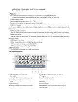
Easy-to-read display
Easily check the operation state in progress by the
simultaneous display of segment level and segmen
t
time, the operation lamps, and the program patter
n
indicated with the bar graph of dots.
Large-capacity program setting
Up to 99 program patterns may be set. Each program
p
attern offers up to 99 segments.
1024 segments maximum:
number of Pattern
× number of segment
Autotuning (AT) with learning function
Search soak areas to conduct Autotuning (AT) to the
segments in turn in the Reset mode (RESET).
Display
RESET RUN FIX MAN HOLD
STEP R.SET
PTN END
PV
TM
H:M:S SV
††150
$
120
>
00<<<100
!
PTN
SEG
OUT1
1
81
85
2 3 4 5 6 7 8 9 10 11 12
A
LM
DO
TS
A
T
OUT2
OUT3
Segment level
Bar graph
of dots
Segment
time
Operation
lamps
Measured
value (PV)
Function
Selectable Sampling cycle
It is possible to switch Sampling cycle between
50 ms, 100 ms and 250 ms.
Program pattern copy function
Easily create new program pattern by copying
p
atterns or segments being programmed.
Pattern 99
Pattern 2
Pattern 1
SEG. 1
Pattern 1
SEG. 2 SEG. 99
Set values management
Setting the Memory group of each segment where
set values such as PID values and Event are store
d
may allow specific control for each segment.
Parameter setting groups
• PID memory group: 8 groups
• Event memory group: 8 groups
• Wait memory group: 8 groups
• Time signal memory group: 16 groups
• Output program memory group:
1 to (128/Maximum segment number)
Selectable PID zones
Level PID and Segment PID may be changed.
400°C
100°C
Level 3
PID memory group 3
Level PID
Level 2
PID memory group 2
Level 1
PID memory group 1
400°C
100°C
Segment PID
Segment
1
PID
memory
group
1
Segment 2
PID
memory
group 2
Segment 3
PID
memory
group 2
Segment 4
PID
memory
group
1
Ramp/Soak stabilizer function
Suppress overshoot when the program shifts from
ramp to soak.
Promote follow-up
Suppress overshoot
Segment level
Ramp area Soak area
Measured value (PV)

1. OUTLINE
IMR02L03-E1
1-3
Loader communication
Use the loader communication port to connect
PF900/901 with the personal computer to set or
monitor parameter set values.
Use with the communication converter,
COM-K (RKC product).
WinUCI-PF900 (monitor and setting tool for
PF900) is required to set or monitor this
instrument by using a personal computer.
To use a personal computer to set or control this
instrument, you must use WinUCI-PF900 software
(monitor and setting tool for PF900).
Refer to the CD-ROM (accessory) or download
from the official RKC website.
RESET RUN FIX MAN HOLD
STEP R.SET
PTN END
PF900
PV
TM H:M:S SV
†††50
$
120
>
00<<<100
!
PTN
SEG
OUT1
1
8 1
8 5
2 3 4 5 6 7 8 9 10 11 12
A
LM
DO
TS
A
T
MONI
OUT2
OUT3
MODE
SET
Communication
converter
Front loader communication port
Personal computer
Two communication ports (optional)
PF900/901 has 2 communication ports: COM port 1
is for the Host communication and COM port 2 is
for Intercontroller communication between
controllers.
Host communication (communication 1)
Connect to the Host devices such as the Host
computer and operation panel by using the Host
communication.
Select communication interface from RS-232C,
RS-422A or RS-485 (when ordering).
Link operation (communication 2)
Connect with single loop temperature controller or
p
rogram controller via Intercontroller
communication to operate master/slave link
operation. No need to use remote setting input by
analog signal or the Host communication.
(Communication interface: RS-485)
Communication
Intercontroller communication
(RS-485)
Host
communication
PF900/PF901
(master)
FB400 (slave)
Maximum connections: 4 controllers
Host computer
Link operation with program controller
Operability
Simple setting by direct key
It is possible to switch operation mode among the
Program control mode, the Fixed set point control
mode, and the Manual control mode by using direc
t
keys in the SV setting & monitor mode. No need to
go to the specific setting display.
Also the type of key operation of the direct keys is
selectable: Press once, Press twice, or Press an
d
hold (2 seconds or more).
To prevent errors, the direct key operation can be
p
rohibited.
PF900/PF901
Maximum connections:
1 controller
RS-232C
Host computer
Connection by RS-232C
RS-422A
or
RS-485
PF900/PF901
Maximum connections: 31 controllers
Host computer
Multi-drop connection by RS-422 or RS-485
Slave controller: PF900/PF901, FB series, RB series

1. OUTLINE
IMR02L03-E1
1-4
1.2 Checking the Product
Before using this product, check each of the following:
z Model code
z Check that there are no scratches or breakage in external appearance (case, front panel, or terminal, etc.)
z Check that all of the items delivered are complete. (Refer to below)
Accessories
Details Q’TY Remarks
Instrument (PF900 or PF901) 1
⎯⎯⎯⎯
Mounting brackets (with screw) 4
⎯⎯⎯⎯
Seal (parts code: SAP-306) 1
⎯⎯⎯⎯
Waterproof/Dustproof rubber
packing
(parts code: KFB900-36<1>)
1 For waterproof/dustproof
Placed on the case
PF900/PF901 User’s Manual
(IMR02L04-E)
1 B6 size (hard copy)
CD-ROM 1 Contents of CD-ROM
• ReadMe
• Communication Setup Tool for PF900/PF901 Program
Controller (WinUCI-PF900)*
• Communication Setup Tool for PF900/PF901 Program
Controller (WinUCI-PF900)
INSTRUCTION MANUAL (IMT01D09-)*
• PF900/PF901 Instruction Manual (IMR02L03-)*
• PF900/PF901 Pattern Record Sheet*
• USB driver for COM-K communication converter*
• Installation USB driver for COM-K communication
converter [IMT01D07-E]*
* This manual can be downloaded from the official RKC website:
http://www.rkcinst.com/english/manual_load.htm.
Sold separately
Details Q’TY Remarks
Terminal cover
(parts code: KFB400-511)
2 Optional
Front cover
(parts code: KF9-35)
1 Optional
Current transformer
CTL-6-P-N [for 0 to 30 A] or
CTL-12-S56-10L-N [for 0 to 100 A]
Depending on the
order quantity
Optional
If any of the products are missing, damaged, or if your manual is incomplete, please contact RKC
sales office or the agent.

1. OUTLINE
IMR02L03-E1
1-5
1.3 Model Code
Check that the product received is correctly specified by referring to the following model code list:
If the product is not identical to the specifications, please contact RKC sales office or the agent.
Suffix code
Suffix code
Specifications
Hardware coding only Quick start code1
PF900
(PV display: Green, SV display: Orange) (1) (2) (3) (4) (5) (6) (7) (8) (9) (10)
PF901
(PV and SV displays: White) − −
*
− /Y
Relay contact M
Voltage pulse V
Voltage/Current [Refer to Output Code Table (P. 1-7)]
Triac T
Output 1 (OUT1)
1
Open collector
D
None N
Relay contact M
Voltage pulse V
Voltage/Current [Refer to Output Code Table (P. 1-7)]
Triac T
Output 2 (OUT2)
1
Open collector D
None N
Voltage pulse V
Voltage/Current [Refer to Output Code Table (P. 1-7)]
Output 3 (OUT3)
1
Open collector
D
24 V AC/DC 3
Power supply voltage
100 to 240 V AC 4
4 points (DO1 to DO4) [Standard] 4
Digital output
(DO1 to DO12)
2
12 points (DO1 to DO12)
C
None N
CT input (2 points) T
CT input or Feedback
resistance input
Feedback resistance input
3
F
None N
Communication 1 (RS-232C) and DI1 to DI6, No communication 2 1
Communication 1 (RS-422A) and DI1 to DI6, No communication 2 4
Communication 1 (RS-485) and DI1 to DI6, No communication 2 5
Communication 1 (RS-232C), Communication 2 (RS-485)
5
and DI1 to DI6 W
Communication 1 (RS-485), Communication 2 (RS-485)
5
and DI1 to DI6 X
Communication 1 (None), Communication 2 (RS-485)
5
and DI1 to DI6 Y
Communication
function
Digital input
(DI1 to DI6)
4
DI1 to DI6
D
No quick start code (Configured at factory set value)
6
N
Specify quick start code 1 1
Quick start code
Specify quick start code 1 and 2 (For Quick start code 2, refer to page 1-9) 2
No specify quick start code No code
PID control with AT (Reverse action) F
PID control with AT (Direct action) D
Heat/Cool PID control with AT (Cooling gain linear type) G
Heat/Cool PID control with AT (for Extruder [air cooling]) A
Heat/Cool PID control with AT (for Extruder [water cooling]) W
Position proportioning PID control without FBR (Reverse action) Z
Control Method
[Quick start code 1]
Position proportioning PID control without FBR (Direct action)
C
No specify quick start code No code
Measured input and
Range
[Quick start code 1]
Refer to Range Code Table. (P.1-7, P. 1-8)
Instrument specification Version symbol
Y
1
Some output types are not specifiable. Refer to the Output type availability on page 1-6.
2
The output type for DO1 to DO4 is Relay: for DO5 to DO12 is Open collector.
3
When Feedback resistance input is specified with other control method than Z or C, the factory set value is fixed to “Z: Position proportioning
PID control without FBR (Reverse action).”
4
Digital input 7 (DI7) to 11 (DI11) are standard.
5
Communication 2 is for the Intercontroller communication.
6
Set initial setting parameters in the Engineering mode. Refer to 4.5.5 Engineering mode (P.4-33) for description of the parameters.

1. OUTLINE
IMR02L03-E1
1-6
Output type availability
PID control with AT [×: Usable −: Not usable]
Details of output
Transmission output
Output type
Manipulated output
value 1 (MV1)
a
Manipulated output
value 2 (MV2)
a
Other
b
Output program
Event output
Relay contact × − − × −
Voltage pulse × − − × −
Voltage/Current × − − × −
Triac × − − × −
Output 1
(OUT1)
Open collector × − − × −
Relay contact × − − × ×
Voltage pulse × − − × ×
Voltage/Current × − × × −
Triac × − − × ×
Output 2
(OUT2)
Open collector × − − × ×
Voltage pulse × − − × ×
Voltage/Current × − × × −
Output 3
(OUT3)
Open collector × − − × ×
a
MV1 and MV2 can be used as Transmission output.
b
Other: Transmission output of Measured value (PV), Deviation value (DEV), Set value (SV) monitor and Segment time (percentage)
Heat/Cool PID control with AT [×: Usable −: Not usable]
Details of output
Transmission output
Output type
Manipulated output
value 1 (MV1)
[heat-side]
a
Manipulated output
value 2 (MV2)
[cool-side]
a
Other
b
Output program
Event output
Relay contact × − − × −
Voltage pulse × − − × −
Voltage/Current × − − × −
Triac × − − × −
Output 1
(OUT1)
Open collector × − − × −
Relay contact × × − × ×
Voltage pulse × × − × ×
Voltage/Current × × × × −
Triac × × − × ×
Output 2
(OUT2)
Open collector × × − × ×
Voltage pulse × × − × ×
Voltage/Current × × × × −
Output 3
(OUT3)
Open collector × × − × ×
a
MV1 and MV2 can be used as Transmission output.
b
Other: Transmission output of Measured value (PV), Deviation value (DEV), Set value (SV) monitor and Segment time (percentage)
Position proportioning PID control without FBR [×: Usable −: Not usable]
Details of output
Transmission output
Output type
Manipulated output
value 1 (MV1)
[open-side]
a
Manipulated output
value 2 (MV2)
[close-side]
a
Other
b
Output program
Event output
Relay contact × − − × −
Voltage pulse × − − × −
Voltage/Current × − − × −
Triac × − − × −
Output 1
(OUT1)
Open collector × − − × −
Relay contact − × − × ×
Voltage pulse − × − × ×
Voltage/Current − × ×
c
× −
Triac − × − × ×
Output 2
(OUT2)
Open collector − × − × ×
Voltage pulse − − − × ×
Voltage/Current − − × × −
Output 3
(OUT3)
Open collector − − − × ×
a
MV1 and MV2 can be used as Transmission output.
b
Other: Transmission output of Measured value (PV), Deviation value (DEV), Set value (SV) monitor and Segment time (percentage)
c
When Position proportioning PID control is selected, it is still possible to assign PV, SV, SV monitor or Transmission output of Segment
time (percentage) to OUT 2 while Manipulated output value 2 (MV2) [close-side] cannot be used.
/