RWLED ROADWAY 50W 78W 105W 125W 150W INSTRUCTIONS
Thank you for buying RAB lighting xtures. Our goal is to design the best quality products to get the job done right. We’d like to hear your comments.
Call the Marketing Department at 888-RAB-1000 or email: marketing@rabweb.com
TM
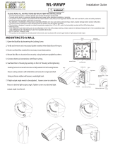
SLIPFITTER MOUNTING
1. The Sliptter ts a 2
3
/8” O.D. Pole Tenon. Place the
Sliptter over the tenon and secure the xture with 2
Set Screws on the side of the Sliptter.
2. Feed wires from Fixture through Sliptter and supply
wires from Pole. Make the necessary connections in the
Sliptter and knot wires for strain relief.
3. To adjust the angle of the Sliptter, remove 2 screws
and remove the Sliptter Cover Plate. Loosen the
Locking Bolt and swivel xture to desired angle. The
graduation on the Sliptter Cover Plate can be used as
guidelines to adjust the angle.
4. Tighten the Locking Bolt. Replace Sliptter Cover Plate.
Tighten Screws.
5. Seal Plug using Teon tape or silicone sealant.
Set
screws
Pole Tenon
Locking Bolt
Fixture
Sliptter
Screws
Plug
Sliptter
cover
plate
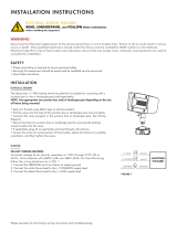
FIXTURE WIRING
Universal voltage driver permits operation at 120 to
277VAC, 50 or 60Hz. Units ordered with (/480V) sux are
480V, 50Hz or 60Hz. Factory ordered xtures with sux
(/PCS) are120V swivel photocell and (/PCS2) are 277V swivel
photocell. 6kV surge protector for 120 to 277VAC, 50 or
60Hz, or 10kV surge protector for 480VAC provided with the
xture. Wire the surge protector in the pole handle away
from the xture and at least 6” above ground.
1. Connect the black xture lead to the (+) LINE supply
lead and black surge protector wire.
2. Connect the white xture lead to the (-) COMMON
supply lead and white surge protector wire.
3. Connect the bare copper Ground wire from xture to
supply ground and green surge protector wire.
CLEANING & MAINTENANCE
CAUTION: Be sure xture temperature is cool enough
to touch. Do not clean or maintain while xture is
energized.
1. Clean glass lens with non-abrasive glass cleaning
solution.
2. Do not open xture to clean the LED. Do not touch the
LED.
TROUBLESHOOTING
1. Check that the line voltage at xture is correct. Refer to
wiring directions.
2. Is the xture grounded properly?
3. Is the photocell functioning properly (if used)?
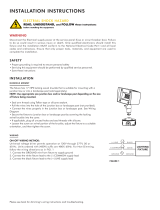
ACCESSORIES
Wedge can be ordered with
WEDGERW-A Bronze Wedge
WEDGERW-W White Wedge
WEDGERW-RG Roadway Gray Wedge
Fixtures with Roadway arm can be provided with
120V -277V twist lock photocell (/PCT)