
99932865 © 2014 Greenlee Textron Inc. IM 1424 REV 2 2/14
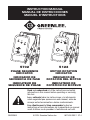
5702
PHASE SEQUENCE
INDICATOR
INDICADOR DE
SECUENCIA DE FASE
INDICATEUR DE
SEQUENCE DE PHASE
INSTRUCTION MANUAL
MANUAL DE INSTRUCCIONES
MANUEL D’INSTRUCTIONS
5123
MOTOR ROTATION
INDICATOR
INDICADOR DE
ROTACIÓN DEL MOTOR
INDICATEUR DE
ROTATION DU MOTEUR
Read and understand all of the instructions and safety
information in this manual before operating or servicing
this tool.
Lea y entienda todas las instrucciones y la información
sobre seguridad que aparecen en este manual, antes de
manejar estas herramientas o darles mantenimiento.
Lire attentivement et bien comprendre toutes les
instructions et les informations sur la sécurité de ce manuel
avant d’utiliser ou de procéder à l’entretien de cet outil.

2
Description
Before connecting a three-phase motor to a three-phase circuit, it is necessary
to match the “legs” or windings of the motor to the phases of the circuit.
This ensures that the motor will rotate in the proper direction when power is
applied to the circuit.
Use the 5123 Motor Rotation Indicator to identify the legs of the motor; use the
5702 Phase Sequence Indicator to identify the phases of the circuit.
Safety
Safety is essential in the use and maintenance of Greenlee tools and
equipment. This manual and any markings on the tool provide information for
avoiding hazards and unsafe practices related to the use of this tool. Observe
all of the safety information provided.
Purpose
This instruction manual is intended to familiarize all personnel with the safe
operation and maintenance procedures for the Greenlee 5702 Phase Sequence
Indicator and 5123 Motor Rotation Indicator.
Keep this manual available to all personnel.
Replacement manuals are available upon request at no charge
at www.greenlee.com.
Do not discard this product or throw away!
For recycling information, go to www.greenlee.com.
All specifications are nominal and may change as design improvements occur.
Greenlee Textron Inc. shall not be liable for damages resulting from misapplication or
misuse of its products.
KEEP THIS MANUAL

5702 • 5123
3
Important Safety InformationDescription
Before connecting a three-phase motor to a three-phase circuit, it is necessary
to match the “legs” or windings of the motor to the phases of the circuit.
This ensures that the motor will rotate in the proper direction when power is
applied to the circuit.
Use the 5123 Motor Rotation Indicator to identify the legs of the motor; use the
5702 Phase Sequence Indicator to identify the phases of the circuit.
Safety
Safety is essential in the use and maintenance of Greenlee tools and
equipment. This manual and any markings on the tool provide information for
avoiding hazards and unsafe practices related to the use of this tool. Observe
all of the safety information provided.
Purpose
This instruction manual is intended to familiarize all personnel with the safe
operation and maintenance procedures for the Greenlee 5702 Phase Sequence
Indicator and 5123 Motor Rotation Indicator.
Keep this manual available to all personnel.
Replacement manuals are available upon request at no charge
at www.greenlee.com.
Do not discard this product or throw away!
For recycling information, go to www.greenlee.com.
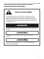
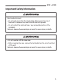
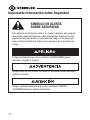
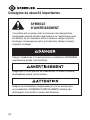
This symbol is used to call your attention to hazards or unsafe
practices which could result in an injury or property damage. The
signal word, defined below, indicates the severity of the hazard. The
message after the signal word provides information for preventing or
avoiding the hazard.
SAFETY ALERT SYMBOL
Immediate hazards which, if not avoided, WILL result in severe injury
or death.
Hazards which, if not avoided, COULD result in severe injury
or death.
Hazards or unsafe practices which, if not avoided, MAY result in
injury or property damage.

4
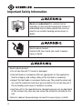
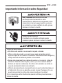
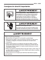
Important Safety Information
Read and understand this material before
operating or servicing this equipment. Failure to
understand how to safely operate this tool can
result in an accident causing serious injury or
death.
Electric shock hazard:
Contact with live circuits can result in severe
injury or death.
Electric shock hazard:
• Do not use the unit if it is wet or damaged.
• Use test leads or accessories that are appropriate for the application.
See the category and voltage rating of the test lead or accessory.
• Inspect the test leads or accessory before use. They must be clean and
dry, and the insulation must be in good condition. Do not use the unit if
the contrasting inner layer of insulation is visible.
• Use this unit for the manufacturer’s intended purpose only, as described
in this manual. Anyotheruse can impair the protection provided by the
unit.
Failure to observe these warnings can result in severe injury or death.

5702 • 5123
5
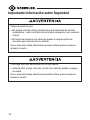
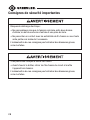
Important Safety Information
Electric shock hazard:
• Do not apply more than the rated voltage between any two input
terminals, or between any input terminal and earth ground.
• Do not contact the test lead tips or any uninsulated portion of the
accessory.
Failure to observe these warnings can result in severe injury or death.
• Do not operate with the case open.
• Before opening the case, remove the test leads from the circuit and shut
off the unit.
Failure to observe these warnings can result in severe injury or death.

6
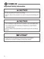
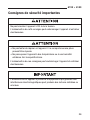
Important Safety Information
Using this unit near equipment that generates electromagnetic
interference can result in unstable or inaccurate readings.
• Do not attempt to repair this unit. It contains no user-serviceable parts.
• Do not expose the unit to extremes in temperature or high humidity.
See Specifications.
Failure to observe these precautions can result in injury and can damage
the unit.
Do not connect the 5123 unit to live voltage.
Failure to observe this precaution can result in injury and can damage the
unit.

5702 • 5123
7
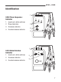
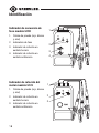
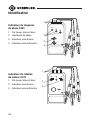
Identification
5123 Motor Rotation
Indicator
1. Leads (red, white and blue)
2. Clockwise Indicator
3. Counterclockwise Indicator
5702 Phase Sequence
Indicator
1. Leads (red, white and blue)
2. Phase Indicators
3. Clockwise Indicator
4. Counterclockwise Indicator
2
3
1
4
2
3
1

8
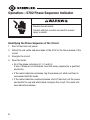
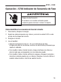
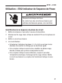
Operation —5702 Phase Sequence Indicator
Electric shock hazard:
Contact with live circuits can result in severe
injury or death.
Identifying the Phase Sequence of the Circuit
1. Shut off and lock out power.
2. Attach the red, white and blue leads of the 5702 to the three phases of the
circuit.
3. Energize the circuit.
4. Read the tester:
• All of the phase indicators (L1, L2 and L3).
If any of these do not illuminate, have the wiring repaired by a qualified
electrician.
• If the meter indicates clockwise, tag the phases red, white and blue to
correspond with the leads.
• If the meter indicates counterclockwise, shut off and lock out the power
and switch the red and white leads. Energize the circuit. The meter will
now indicate clockwise.

5702 • 5123
9
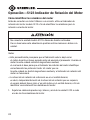
Operation—5123 Motor Rotation Indicator
Notes:
• This procedure assumes that the motor was “bumped,” or run for a short
period of time, by the motor manufacturer prior to shipment.
A bumped motor will retain residual magnetism, which is the basis for the
Motor Rotation Indicator to correctly identify the legs of the motor. A motor
that has not been bumped will not have any residual magnetism and the
Motor Rotation Indicator will not work.
• Clockwise is the reference direction — regardless of the required direction
of motor rotation, the user must spin the motor shaft clockwise to correctly
identify the motor wires.
1. Attach the red, white and blue leads of the 5123 to the three motor wires.
Identifying Motor Wires
Before connecting a three-phase motor to a circuit, use the 5123 Motor
Rotation Indicator to identify the wires for correct motor rotation.
Do not connect the 5123 unit to live voltage.
Failure to observe this precaution can result in injury and can damage
the unit.

10
Operation—5123 Motor Rotation Indicator (cont’d)
2. Press the test button while rotating the shaft clockwise.
• If clockwise rotation is required and the clockwise indicator is
illuminated, tag the motor wires to correspond with the Motor Rotation
Indicator leads.
• If clockwise rotation is required and the counterclockwise indicator
is illuminated, switch the red and white leads and re-test. When the
clockwise indicator illuminates, tag the motor wires to correspond with
the Motor Rotation Indicator leads.
• If counterclockwise rotation required and the counterclockwise
indicator is illuminated, tag the motor wires to correspond with the Motor
Rotation Indicator leads.
• If counterclockwise rotation is required and the clockwise indicator
is illuminated, switch the red and white leads and re-test. When the
clockwise indicator illuminates, tag the motor wires to correspond with
the Motor Rotation Indicator leads.
3. Shut off and lock out power. Connect the motor wires to correspond to the
phases of the circuit. Energize the circuit.

5702 • 5123
11
Battery Replacement (5123)
1. Disconnect the unit from the circuit. Turn the unit OFF.
2. Remove the screw from the battery compartment cover.
3. Remove the cover and shake out the battery.
4. Replace the battery (observe polarity).
5. Replace the battery compartment cover and screw.
Before opening the case, remove the test leads from the circuit and shut
off the unit.
Failure to observe these warnings can result in severe injury or death.

12
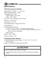
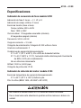
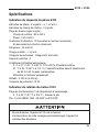
Specifications
5702 Phase Sequence Indicator
Phase Indication: 3 lamps — L1, L2 and L3
Rotational Field Indication: 2 lamps
Voltage Range (line to line):
Rotational Field: 80 V to 440 V
Phase: 190 V to 600 V
Duty cycle: 20 sec. ON (max), 60 sec OFF (min)
Frequency: 50 Hz to 60 Hz
Current Load: < 3.5 mA
Overvoltage Category: Category III, 600 Volts
Pollution Degree: 2
Operating/Storage Conditions:
0 °C to 31 °C (32 °F to 88 °F), 0% to 80% relative humidity
31 °C to 45 °C (88 °F to 113 °F), relative humidity decreasing linearly from
80% to 50% (non-condensing)
Indoor use only
Altitude: 2000 m (6500')
Protection Category: IP 40
5123 Motor Rotation Indicator
Operating/Storage Temperature Range: 0 °C to 40 °C (32 °F to 104 °F)
Remove battery
Battery: 9-Volt (NEDA 1604, JIS 006P or IEC 6F22)
Do not connect the 5123 unit to live voltage.
Failure to observe this precaution can result in injury and can damage
the unit.
Page is loading ...
Page is loading ...
Page is loading ...
Page is loading ...
Page is loading ...
Page is loading ...
Page is loading ...
Page is loading ...
Page is loading ...
Page is loading ...
Page is loading ...
Page is loading ...
Page is loading ...
Page is loading ...
Page is loading ...
Page is loading ...
Page is loading ...
Page is loading ...
Page is loading ...
Page is loading ...
Page is loading ...
Page is loading ...
Page is loading ...
Page is loading ...
-
 1
1
-
 2
2
-
 3
3
-
 4
4
-
 5
5
-
 6
6
-
 7
7
-
 8
8
-
 9
9
-
 10
10
-
 11
11
-
 12
12
-
 13
13
-
 14
14
-
 15
15
-
 16
16
-
 17
17
-
 18
18
-
 19
19
-
 20
20
-
 21
21
-
 22
22
-
 23
23
-
 24
24
-
 25
25
-
 26
26
-
 27
27
-
 28
28
-
 29
29
-
 30
30
-
 31
31
-
 32
32
-
 33
33
-
 34
34
-
 35
35
-
 36
36


Greenlee 5702 User manual
- Type
- User manual
- This manual is also suitable for
Ask a question and I''ll find the answer in the document
Finding information in a document is now easier with AI
in other languages
- français: Greenlee 5702 Manuel utilisateur
- español: Greenlee 5702 Manual de usuario
Related papers
-
Greenlee GT-15 Low Voltage Detector User manual
-
-
-
Greenlee GT-12 User manual
-
-
-
-
-
-