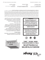
Garland RBA Series radiant char-broilers are designed to provide efficient and high-temperature cooking for a variety of food items. With its heavy-duty construction and stainless steel exterior, the RBA Series is built to withstand the demands of a commercial kitchen. The char-broilers feature adjustable legs for easy leveling, a built-in drip tray for collecting grease, and a variety of burner options to accommodate different cooking needs.
Garland RBA Series radiant char-broilers are designed to provide efficient and high-temperature cooking for a variety of food items. With its heavy-duty construction and stainless steel exterior, the RBA Series is built to withstand the demands of a commercial kitchen. The char-broilers feature adjustable legs for easy leveling, a built-in drip tray for collecting grease, and a variety of burner options to accommodate different cooking needs.


-
 1
1
-
 2
2
-
 3
3
-
 4
4
-
 5
5
-
 6
6
-
 7
7
-
 8
8
-
 9
9
-
 10
10
-
 11
11
-
 12
12
-
 13
13
-
 14
14
-
 15
15
-
 16
16
-
 17
17
-
 18
18
-
 19
19
-
 20
20


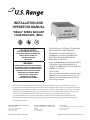
Garland RBA Series User manual
- Type
- User manual
- This manual is also suitable for
Garland RBA Series radiant char-broilers are designed to provide efficient and high-temperature cooking for a variety of food items. With its heavy-duty construction and stainless steel exterior, the RBA Series is built to withstand the demands of a commercial kitchen. The char-broilers feature adjustable legs for easy leveling, a built-in drip tray for collecting grease, and a variety of burner options to accommodate different cooking needs.
Ask a question and I''ll find the answer in the document
Finding information in a document is now easier with AI
in other languages
- français: Garland RBA Series Manuel utilisateur
Related papers
-
Garland MST54 Owner Instruction Manual
-
-
Garland GTGG24-G24 User guide
-
Garland M42 M42R M42T M42S Owner Instruction Manual
-
Garland GTOG36-6 Operating instructions
-
-
Garland 4522970 REV 1 User manual
-
-
-
Other documents
-
U.S. Range "REGAL" SERIES Operating instructions
-
Thor GH103-N Technical & Service Manual
-
Vulcan-Hart ML-136590 User manual
-
Wells Manufacturing HDCB-2430G Operating instructions
-
Vulcan Hart HGB50M-ML-27886 Operating instructions
-
2Wire HDCR-1230G Owner's manual
-
Vulcan Hart ML-52211 Specification
-
Vulcan 36RB Owner's manual
-
-
Star 8136RCBA-1-2 Owner's manual