Garland M42 M42R M42T M42S Owner Instruction Manual

Category
Barbecues & grills
Type
Owner Instruction Manual
© 2010 Garland Commercial Ranges Limited
FOR YOUR SAFETY:
DO NOT STORE OR USE GASOLINE
OR OTHER FLAMMABLE VAPORS OR
LIQUIDS IN THE VICINITY OF
THIS OR ANY OTHER
APPLIANCE
WARNING:
IMPROPER INSTALLATION, ADJUSTMENT,
ALTERATION, SERVICE OR MAINTENANCE
CAN CAUSE PROPERTY DAMAGE, INJURY,
OR DEATH. READ THE INSTALLATION,
OPERATING AND MAINTENANCE
INSTRUCTIONS THOROUGHLY
BEFORE INSTALLING OR
SERVICING THIS EQUIPMENT
PLEASE READ ALL SECTIONS OF THIS MANUAL
AND RETAIN FOR FUTURE REFERENCE.
THIS PRODUCT HAS BEEN CERTIFIED AS
COMMERCIAL COOKING EQUIPMENT AND
MUST BE INSTALLED BY PROFESSIONAL
PERSONNEL AS SPECIFIED.
IN THE COMMONWEALTH OF MASSACHUSETTS
THIS PRODUCT MUST BE INSTALLED BY A
LICENSED PLUMBER OR GAS FITTER. APPROVAL
NUMBER: G-1-07-05-28
For Your Safety:
Post in a prominent location, instructions to be
followed in the event the user smells gas. This
information shall be obtained by consulting
your local gas supplier.
Français . . . . . . . . . . . . . . . . . . . . . . . . . . . . . . . . . . . . . . . . . . . . . . . . . . . . . . . . . . . . . . . . . . . . . . . . . . . . . . . . . . . . . . . . . . . . . . Page 17
Españo. . . . . . . . . . . . . . . . . . . . . . . . . . . . . . . . . . . . . . . . . . . . . . . . . . . . . . . . . . . . . . . . . . . . . . . . . . . . . . . . . . . . . . . . . . . . . Página 33
Users are cautioned that maintenance and repairs must be performed by a Garland/US Range authorized service
agent using genuine Garland/US Range replacement parts. Garland/US Range will have no obligation with
respect to any product that has been improperly installed, adjusted, operated or not maintained in accordance
with national and local codes or installation instructions provided with the product, or any product that has its
serial number defaced, obliterated or removed, or which has been modified or repaired using unauthorized parts
or by unauthorized service agents. For a list of authorized service agents, please refer to the Garland/US Range web
site at http://www.Garland-Group.com. The information contained herein, (including design and parts specifications),
may be superseded and is subject to change without notice.
Part # 4531237 Rev 2 (09/09/13)
INSTALLATION AND
OPERATION MANUAL
GARLAND GT SERIES
HEAVY DUTY GAS
COUNTER EQUIPMENT
Page 2
IMPORTANT INFORMATION
WARNING:
This product contains chemicals known to the state of California to cause cancer and/or birth defects
or other reproductive harm. Installation and servicing of this product could expose you to airborne
particles of glass wool/ceramic fibers. Inhalation of airborne particles of glass wool/ceramic fibers
is known to the state of California to cause cancer. Operation of this product could expose you to
carbon monoxide if not adjusted properly. Inhalation of carbon monoxide is known to the state of
California to cause birth defects or other reproductive harm.
Keep appliance area free and clear of combustibles.
Part # 4531237 Rev 2 (09/09/13)
Page 3
TABLE OF CONTENTS
SPECIFICATIONS: HOT PLATES . . . . . . . . . . . . . . . . . . . . . . . . . . . . . . . . . . . . . . . . . . . . 4
SPECIFICATIONS: STEP-UP HOT PLATES. . . . . . . . . . . . . . . . . . . . . . . . . . . . . . . . . . . . 5
SPECIFICATIONS: CERAMIC-BRIQUETTE CHAR-BROILERS. . . . . . . . . . . . . . . . . . . . 6
SPECIFICATIONS: RADIANT CHAR-BROILERS . . . . . . . . . . . . . . . . . . . . . . . . . . . . . . . 7
SPECIFICATIONS: GRIDDLES . . . . . . . . . . . . . . . . . . . . . . . . . . . . . . . . . . . . . . . . . . . . . . 8
PRE INSTALLATION. . . . . . . . . . . . . . . . . . . . . . . . . . . . . . . . . . . . . . . . . . . . . . . . . . . . . . . 9
Damage Check . . . . . . . . . . . . . . . . . . . . . . . . . . . . . . . . . . . . . . . . . . . . . . . . . . . . . . . . . . . . . . . . . . . . . . . . .9
Rating Plate . . . . . . . . . . . . . . . . . . . . . . . . . . . . . . . . . . . . . . . . . . . . . . . . . . . . . . . . . . . . . . . . . . . . . . . . . . . .9
INSTALLATION . . . . . . . . . . . . . . . . . . . . . . . . . . . . . . . . . . . . . . . . . . . . . . . . . . . . . . . . . . . 9
General . . . . . . . . . . . . . . . . . . . . . . . . . . . . . . . . . . . . . . . . . . . . . . . . . . . . . . . . . . . . . . . . . . . . . . . . . . . . . . . .9
Gas Connections . . . . . . . . . . . . . . . . . . . . . . . . . . . . . . . . . . . . . . . . . . . . . . . . . . . . . . . . . . . . . . . . . . . . . . .9
Leg Installation. . . . . . . . . . . . . . . . . . . . . . . . . . . . . . . . . . . . . . . . . . . . . . . . . . . . . . . . . . . . . . . . . . . . . . . .10
Ventilation . . . . . . . . . . . . . . . . . . . . . . . . . . . . . . . . . . . . . . . . . . . . . . . . . . . . . . . . . . . . . . . . . . . . . . . . . . . .11
Air Supply. . . . . . . . . . . . . . . . . . . . . . . . . . . . . . . . . . . . . . . . . . . . . . . . . . . . . . . . . . . . . . . . . . . . . . . . . .11
ADJUSTMENTS. . . . . . . . . . . . . . . . . . . . . . . . . . . . . . . . . . . . . . . . . . . . . . . . . . . . . . . . . . 11
Burner Adjustments – All Models. . . . . . . . . . . . . . . . . . . . . . . . . . . . . . . . . . . . . . . . . . . . . . . . . . . . . . . 11
OPERATION: ALL MODELS . . . . . . . . . . . . . . . . . . . . . . . . . . . . . . . . . . . . . . . . . . . . . . . 12
Lighting Standing Pilots - All Models . . . . . . . . . . . . . . . . . . . . . . . . . . . . . . . . . . . . . . . . . . . . . . . . . . .12
Shutdown Procedure . . . . . . . . . . . . . . . . . . . . . . . . . . . . . . . . . . . . . . . . . . . . . . . . . . . . . . . . . . . . . . . . . .12
MAINTENANCE & CLEANING . . . . . . . . . . . . . . . . . . . . . . . . . . . . . . . . . . . . . . . . . . . . . 13
Seasoning. . . . . . . . . . . . . . . . . . . . . . . . . . . . . . . . . . . . . . . . . . . . . . . . . . . . . . . . . . . . . . . . . . . . . . . . . . . . .13
Griddle (standard steel plate) . . . . . . . . . . . . . . . . . . . . . . . . . . . . . . . . . . . . . . . . . . . . . . . . . . . . . . .13
Griddle (optional chrome) . . . . . . . . . . . . . . . . . . . . . . . . . . . . . . . . . . . . . . . . . . . . . . . . . . . . . . . . . .13
Cast Iron Top Grates (Hot Plates & Char-Broilers) . . . . . . . . . . . . . . . . . . . . . . . . . . . . . . . . . . . . .13
Cleaning . . . . . . . . . . . . . . . . . . . . . . . . . . . . . . . . . . . . . . . . . . . . . . . . . . . . . . . . . . . . . . . . . . . . . . . . . . . . . .14
Griddle . . . . . . . . . . . . . . . . . . . . . . . . . . . . . . . . . . . . . . . . . . . . . . . . . . . . . . . . . . . . . . . . . . . . . . . . . . . .14
Open Top Burners . . . . . . . . . . . . . . . . . . . . . . . . . . . . . . . . . . . . . . . . . . . . . . . . . . . . . . . . . . . . . . . . . .14
Cast Iron Top Grates . . . . . . . . . . . . . . . . . . . . . . . . . . . . . . . . . . . . . . . . . . . . . . . . . . . . . . . . . . . . . . . .14
Char-Broilers . . . . . . . . . . . . . . . . . . . . . . . . . . . . . . . . . . . . . . . . . . . . . . . . . . . . . . . . . . . . . . . . . . . . . . .15
Stainless Steel . . . . . . . . . . . . . . . . . . . . . . . . . . . . . . . . . . . . . . . . . . . . . . . . . . . . . . . . . . . . . . . . . . . . . .15
Part # 4531237 Rev 2 (09/09/13)
Page 4
SPECIFICATIONS: HOT PLATES
Part # 4531237 Rev 2 (09/09/13)
32.0”
[814mm]
27.2”
[691mm]
4.0”
[102mm]
4.0”
[102mm]
15.8”
[402mm]
13.0”
[330mm]
26.0”
[660mm]
5.3”
[136mm]
WIDTH
4.0”
[102mm]
1.7”
[43mm]
1.7”
[43mm]
7.6”
[192mm]
STRAIGHT (STD) OR FLUSH-REAR
GAS INLET w/REGULATOR
For use with Natural or Propane gas only.
Gas input ratings shown for installations up to
2000 ft., (610m), above sea level. Please specify
altitudes over 2000 ft. and gas type when ordering.
Garland/U.S. Range products are not approved
or authorized for home or residential use, but are
intended for commercial applications only.
Garland/U.S. Range will not provide service,
warranty, maintenance or support of any kind
other than in commercial applications.
* Please add 5” (127mm) in overall depth
with attachment condiment rail option
.
*
Model #
Width
In (mm)
Height
(w/std legs)
Depth
In (mm)
Total Input (BTU) Shipping Information
NAT PRO Lbs/Kg Cu Ft
GTOG12-2 11-13/16 (300)
13 (330) 32 (814)
60,000 52,000 73/33 4
GTOG24-4 23-5/8 (600) 120,000 104,000 135/61 8
GTOG36-6 35-7/16 (900) 180,000 156,000 191/87 25
GTOG48-8 47-1/4 (1200) 240,000 208,000 247/112 33
SUPPLY OPERATING PRESSURE MANIFOLD OPERATING PRESSURE CLEARANCES
NATURAL GAS PROPANE NATURAL GAS PROPANE INSTALLATION TO COMBUSTIBLE
"WCMBar"WCMbar"WCMBar"WCMbar Sides Rear
7 17.5 11 27. 5 4.5 11 10 24.5 7 (178mm) 6 (152mm)
Page 5
SPECIFICATIONS: STEP-UP HOT PLATES
Part # 4531237 Rev 2 (09/09/13)
32.0”
[814mm]
27.2”
[691mm]
4.0”
[102mm]
14.5”
[368mm]
4.0”
[102mm]
4.0”
[102mm]
19.8”
[503mm]
13.0”
[330mm]
26.0”
[660mm]
5.3”
[136mm]
WIDTH
4.0”
[102mm]
1.7”
[43mm]
1.7”
[43mm]
7.6”
[192mm]
STRAIGHT (STD) OR FLUSH-REAR
GAS INLET w/REGULATOR
For use with Natural or Propane gas only.
Gas input ratings shown for installations up to
2000 ft., (610m), above sea level. Please specify
altitudes over 2000 ft. and gas type when ordering.
Garland/U.S. Range products are not approved
or authorized for home or residential use, but are
intended for commercial applications only.
Garland/U.S. Range will not provide service,
warranty, maintenance or support of any kind
other than in commercial applications.
Model #
Width
In (mm)
Height
(w/std legs)
Depth
In (mm)
Total Input (BTU) Shipping Information
NAT PRO Lbs/Kg Cu Ft
GTOG24-SU4 23-5/8 (600)
19-13/16 (503) 32 (814)
120,000 108,000 135/61 8
GTOG36-SU6 35-7/16 (900) 180,000 162,000 191/87 25
GTOG48-SU8 47-1/4 (1200) 240,000 216,000 247/112 33
SUPPLY OPERATING PRESSURE MANIFOLD OPERATING PRESSURE CLEARANCES
NATURAL GAS PROPANE NATURAL GAS PROPANE INSTALLATION TO COMBUSTIBLE
"WCMBar"WCMbar"WCMBar"WCMbar Sides Rear
7 17.5 11 27. 5 4.5 11 10 24.5 7" (178mm) 6 (152mm)
* Please add 5” (127mm) in overall depth
with attachment condiment rail option
.
*
Page 6
SPECIFICATIONS: CERAMIC-BRIQUETTE CHAR-BROILERS
Part # 4531237 Rev 2 (09/09/13)
32.1”
[814mm]
4.0”
[102mm]
4.0”
[102mm]
2.4”
[62mm]
TROUGH
DEPTH
1.4” [35mm] HANDLE DEPTH MAX
15.9”
[404mm]
13.0”
[330mm]
21.2”
[538mm]
GRATE DEPTH
5.5°
HIGH GRATE
POSITION
1.4°
LOW GRATE POSITION
26.0”
[660mm]
5.3”
[136mm]
WIDTH
4.0”
[102mm]
1.7”
[43mm]
1.7”
[43mm]
7.6”
[192mm]
STRAIGHT (STD) OR FLUSH-REAR
GAS INLET w/REGULATOR
For use with Natural or Propane gas only.
Gas input ratings shown for installations up to
2000 ft., (610m), above sea level. Please specify
altitudes over 2000 ft. and gas type when
ordering.
Garland/U.S. Range products are not approved
or authorized for home or residential use, but
are intended for commercial applications only.
Garland/U.S. Range will not provide service,
warranty, maintenance or support of any kind
other than in commercial applications.
* Please add 5” (127mm) in overall depth
with attachment condiment rail option
.
*
3/4” (83mm) DIVIDER ON
GTBG48-AB48 and GTBG60-AB60
adjustable broilers
.
Model #
Width
In (mm)
Height
(w/std legs)
Depth
In (mm)
Total
Input (BTU)
Shipping Information
Lbs/Kg Cu Ft
GTBG24-AB24 23-5/8 (600)
13 (330) 32 (814)
60,000 283/129 19
GTBG36-AB36 35-7/16 (900) 90,000 391/178 26
GTBG48-AB48 47-1/4 (1200) 120,000 514/283 34
GTBG60-AB60 59-1/16 (1500) 150,000 635/288 41
SUPPLY OPERATING PRESSURE MANIFOLD OPERATING PRESSURE INSTALLATION CLEARANCES
NATURAL GAS PROPANE NATURAL GAS PROPANE
CLEARANCE: 0”
FOR INSTALLATION IN
NON-COMBUSTIBLE
SURROUNDINGS ONLY
"WCMBar"WCMbar"WCMBar"WCMbar
7 17. 5 11 27. 5 4 . 5 11 10 24 . 5
3.3” (84mm) DIVIDER ON
GTBG48-AB48 and GTBG60-AB60
adjustable broilers.
Page 7
SPECIFICATIONS: RADIANT CHAR-BROILERS
Part # 4531237 Rev 2 (09/09/13)
32.1”
[814mm]
4.0”
[102mm]
4.0”
[102mm]
2.4”
[62mm]
TROUGH
DEPTH
1.4” [35mm] HANDLE DEPTH MAX
15.9”
[404mm]
13.0”
[330mm]
21.2”
[538mm]
GRATE DEPTH
5.5°
HIGH GRATE
POSITION
1.4°
LOW GRATE POSITION
26.0”
[
660mm
]
5.3”
[136mm]
WIDTH
4.0”
[102mm]
1.7”
[43mm]
1.7”
[43mm]
7.6”
[192mm]
STRAIGHT (STD) OR 3/4" N.P.T.
FLUSH REAR GAS INLET w/REGULATOR
Garland/U.S. Range products are not approved
or authorized for home or residential use, but are
intended for commercial applications only. Garland/
U.S. Range will not provide service, warranty, main-
tenance or support of any kind other than in com-
mercial applications.
ADJUSTABLE GRATE
21.2”
[538mm]
GRATE DEPTH
5.5°
GRATE ANGLE
NON-ADJUSTABLE GRATE
*
* Please add 5” (127mm) in overall depth
with attachment condiment rail option
.
3/4” (83mm) DIVIDER ON
GTBG48-AR48 and GTBG60-AR60
adjustable broilers.
For use with Natural or Propane gas only. Gas input
ratings shown for installations up to 2000 ft. (610m),
above sea level. Please specify altitudes over 2000
ft. and gas type when ordering.
Model #
Width
In (mm)
Height
(w/std legs)
Depth
In (mm)
Total
Input (BTU)
Shipping Information
Lbs/Kg Cu Ft
With Adjustable Grates
GTBG24-AR24 23-5/8 (600)
13 (330) 32 (814)
72,000 283/129 19
GTBG36-AR36 35-7/16 (900) 108,000 391/178 26
GTBG48-AR48 47-1/4 (1200) 144,000 514/283 34
GTBG60-AR60 59-1/16 (1500) 180,000 635/288 41
With Non-Adjustable Grates
GTBG24-NR24 23-5/8 (600)
13 (330) 32 (814)
72,000 283/129
18
GTBG36-NR36 35-7/16 (900) 108,000 391/178
25
GTBG48-NR48 47-1/4 (1200) 144,000 514/283
33
GTBG60-NR60 59-1/16 (1500) 180,000 635/288
40
SUPPLY OPERATING PRESSURE MANIFOLD OPERATING PRESSURE INSTALLATION CLEARANCES
NATURAL GAS PROPANE NATURAL GAS PROPANE
CLEARANCE: 0”
FOR INSTALLATION IN
NON-COMBUSTIBLE
SURROUNDINGS ONLY
"WCMBar"WCMbar"WCMBar"WCMbar
7 17. 5 11 27. 5 4 . 5 11 10 24 . 5
3.3” (84mm) DIVIDER ON
GTBG48-AR48 and GTBG60-AR60
adjustable broilers.
Page 8
SPECIFICATIONS: GRIDDLES
Part # 4531237 Rev 2 (09/09/13)
2.0"
7.6"
WIDTH
16.3"
4.0"
1.7"
32.1"
4.0"
4.0"
25.9"
13.0"
15.8"
20.5"
23.0"
3.8"
0.8"
5.3"
(51mm)
CORD
OPT.ELEC.IGN.
(21mm)
(584mm)
(98mm)
OPT.ELEC.IGN.
CORD
GAS INLET W/REGULATOR
STRAIGHT (STD) OR FLUSH REAR
TROUGH DEPTH
(43mm)
(192mm)
(43mm)
(814mm)
(102mm)
(102mm)
(102mm)
(415mm)
(402mm)
(330mm)
(521mm)
(657mm)
(136mm)
GAS
INLET
1.7"
For use with Natural or Propane gas only. Gas
input ratings shown for installations up to 2000 ft.,
(610m), above sea level. Please specify altitudes
over 2000 ft. and gas type required when ordering.
Garland/U.S. Range products are not approved
or authorized for home or residential use, but
are intended for commercial applications only.
Garland / U.S. Range will not provide service,
warranty, maintenance or support of any kind
other than in commercial applications.
* Please add 7” (178mm) in overall depth
with attachment condiment rail option.
Model #
Width
In (mm)
Height
(w/std legs)
Depth
In (mm)
Total
Input (BTU)
Shipping
Information
Lbs/Kg Cu Ft
Thermostat Controlled Standard Griddle (1" steel plate)
GTGG24-GT24M 23-5/8 (600)
13 (330) 32 (814)
56,000 290/132 21
GTGG36-GT36M 35-7/16 (900) 84,000 405/184 29
GTGG48-GT48M 47-1/4 (1200) 112,000 595/270 37
GTGG60-GT60M 59-1/16 (1500) 140,000 705/320 42
GTGG72-GT72M 70-7/8 (1800) 168,000 810/368 50
Manually Controlled Standard Griddle (1" steel plate)
GTGG24-G24M 23-5/8 (600)
13 (330) 32 (814)
54,000
280/127 21
GTGG36-G36M 35-7/16 (900) 81,000
395/180 29
GTGG48-G48M 47-1/4 (1200) 108,000
585/266 37
GTGG60-G60M 59-1/16 (1500) 135,000
688313 42
GTGG72-G72M 70-7/8 (1800) 162,000
790/359 50
SUPPLY OPERATING PRESSURE MANIFOLD OPERATING
PRESSURE
CLEARANCES
NATURAL GAS PROPANE NATURAL GAS PROPANE INSTALLATION TO
COMBUSTIBLE
"WC MBar "WC Mbar "WC MBar "WC Mbar Sides Rear
7 17.5 11 27.5 4.5 11 10 24.5 6" (152mm) 6” (152mm)
Page 9
PRE INSTALLATION
INSTALLATION
General
1. Carefully remove appliance from carton or crate. Burner
tie wires and other packing material should be removed
at this time. The protective material covering the stainless
steel should be removed immediately after the appliance
is installed, before it is  red.
2. Remove top grates and place out of the way, to prevent
damage.
3. These appliances must be installed under an adequate
ventilation system. Refer to section titled Ventilation for
further instructions.
4. All burner adjustments and setting shall be made by a
quali ed gas technician.
Gas Connections
The local gas authority should be consulted at the
installation planning stage in order to establish the
availability of an adequate supply of gas and to ensure
that the meter is adequate for the required  ow rate. The
pipe work from the meter to the appliance must be an
appropriate size.
All  xed (non-mobile) appliances MUST be  tted with an
accessible upstream gas shut o valve as a means of isolating
the appliance for emergency shut o and for servicing. A
union or similar means of disconnection must be provided
between the gas-cock and the appliance.
A manually operable valve must be  tted to the gas supply
to the kitchen to enable it to be isolated in an emergency.
Wherever practical, this shall be located either outside the
kitchen or near to an exit in a readily accessible position.
Where it is not practical to do this, an automatic isolation
valve system shall be  tted which can be operated from a
readily accessible position near to the exit.
In locations where the manual isolation valve is  tted or the
automatic system can be reset this notice MUST be posted:
ALL DOWNSTREAM BURNER AND PILOT VALVES MUST
BE TURNED OFF PRIOR TO ATTEMPTING TO RESTORE THE
SUPPLY. AFTER EXTENDED SHUT OFF, PURGE BEFORE
RESTORING GAS.
Damage Check
Damage check: Check carton or crate for possible damage
incurred in shipping. After carefully un-crating, check for
concealed” damage. Report any damage immediately to
your carrier.
Rating Plate
The rating plate is a xed to a bracket mounted at the rear
of the unit but visible from the front. The grease drawer may
need to be removed to view rating plate.
The correct type of gas for which the unit was manufactured
is noted on the rating plate, and this type of gas must be
used.
When corresponding with the factory or your local
authorized factory service center regarding service problems
or replacement parts, be sure to refer to the particular model
by the correct model number (including the pre x and
su x letters and numbers) and the warranty serial number.
The rating plate a xed to the appliance contains this
information.
We suggest installation, maintenance and repairs be
performed by your local authorized service agency listed in
your information manual pamphlet.
In the event you have any questions concerning the
installation, use, care or service of the product, write or call
our Product Service Department.
This product must be installed by professional personnel as
speci ed. Garland/U.S. Range products are not approved or
authorized for home or residential use, but are intended for
commercial applications only. Garland / U.S. Range will not
provide service, warranty, maintenance or support of any
kind other than in commercial applications.
Part # 4531237 Rev 2 (09/09/13)
Page 10
INSTALLATION
1. The installation and connection must be performed by a
licensed gas technician in compliance with local codes,
or in the absence of local codes, with CAN/CGA-B149
Installation Code or with the national Fuel Gas Code, ANSI
Z223.1/NFPA No. 54 – Latest Edition.
2. The correct type of gas for which the unit was
manufactured is noted on the rating plate, and this type
of gas must be used.
3. If it is a new installation have the gas authorities check
meter size and piping to assure that the appliance is
supplied with necessary amount of gas pressure required
to operate properly.
4. The gas pressure must be checked when the appliance
is installed, to ensure that the gas pressure is the same
as speci ed on the rating plate. If necessary, pressure
adjustments can be made at the pressure regulator,
supplied on each unit.
NOTE: When installing as a  ush mount pressure regulator
connection, (to allow for equipment installations against
a non-combustible wall), a certi ed exible gas hose and
quick disconnect assembly is required to allow the unit to
be moved in the event an adjustment of the gas pressure
regulator is required.
5. Have a quali ed gas technician check the gas pressure
to make certain that existing gas facilities (meter, piping,
etc.) will deliver the BTU’s of gas required at the appliance
with no more than ½” water column pressure drop. When
checking pressure, be certain that all the equipment on
same gas line is turned to the “ON” position.
6. The appliance and its individual shut o valve must be
disconnected from the gas supply piping system during
any pressure testing of that system at test pressures in
excess of 1/2 PSIG. (3.45 KPA).
7. The appliance must be isolated from the gas supply
piping system by closing its individual manual shut o
valve during any pressure testing of the gas supply piping
system at test pressures equal to or less than 1/2 PSIG.
(3.45 KPA).
8. Make certain that the new piping, joints and connections
have been made in a clean manner and have been
purged, so that the piping compound, chips, etc., will not
clog pilots, valves and/or controls. Use pipe joint sealant
that is certi ed for use with lique ed petroleum gas.
9. WARNING: Check gas connections for leaks, using soap
solution or similar means.
Do Not Check with an Open Flame.
Leg Installation
Your new appliance has been supplied with 4”(102mm)
adjustable legs. These legs are threaded into holes on the
bottom. Once the legs are installed turn the leveling foot at
the bottom of the leg.
UNDERSIDE OF UNIT
4" [102mm]
ADJUSTABLE LEG
LEG INSTALLATION
LEVELING FOOT
Level the appliance by adjustment of leveling bolts or legs.
Use a spirit level and check for level four ways; across front
and back, then down left and right edges. Level any adjacent
units to the  rst. A griddle may not rest evenly on the
appliance body if it is not properly leveled.
Part # 4531237 Rev 2 (09/09/13)
Page 11
INSTALLATION
Ventilation
Ventilation requirements may be subject to local
building and  re codes. Consult local authorities
having jurisdiction.
Counter equipment must be installed in a location in which
the facilities for ventilation permit satisfactory combustion
of gas and proper venting. Proper ventilation is imperative
for good operation of the appliance. The ideal method
of ventilating counter equipment is the use of a properly
designed ventilating canopy, which should extend at least
6”/152mm beyond all sides of the appliance (except against
the wall if the canopy is a wall installation). This is usually part
of a mechanical exhaust system.
Air Supply
1. It is necessary that su cient room air ingress be allowed
to compensate for the amount of air removed by any
ventilating system. Otherwise, a subnormal atmospheric
pressure will occur, a ecting the appliance operation
adversely and causing undesirable working conditions.
2. Appliances shall be located so as not to interfere with
proper circulation of air within the con ned space. All gas
burners and pilots require su cient air to operate.
3. Large objects should not be placed in front of the
appliance which might obstruct the air  ow through
the front. Do not obstruct the  ow of combustion and
ventilation air.
4. Do not permit fans to blow directly at the appliance, and
wherever possible, avoid open windows adjacent to the
appliance sides and back; also wall type fans which create
air cross-currents within the room.
ADJUSTMENTS
Burner Adjustments – All Models
1. Before making any adjustment, turn all gas valves
to “OFF”. Remove the burner tie wires, if not already
removed. Be sure all piping is gas tight and that air is
purged from lines.
2. All units are shipped from factory at burner ratings set
for the gas speci ed on the rating plate at normal gas
pressure. The only adjustment necessary is for that
governing air.
Air Adjustment: If necessary, the air is adjusted by rotating
the air shutter on burner. The burner must have enough air
that the tips of the  ames are not yellow, but not so much air
that the  ames will lift o the burner ports. Securely tighten
air shutter screw so air shutter cannot be moved.
NOTE: All adjustments must be performed by a quali ed gas
technician.
Part # 4531237 Rev 2 (09/09/13)
Page 12
Lighting Standing Pilots - All Models
After the appliance has been installed by a licensed gas
trades-person all connections, pilot lights and controls have
been inspected for proper operation. All gas appliances
that use standing pilot systems are generally assumed to
be operating with the pilot on continuously. The appliances
should not be restarted except in the event of a gas service
interruption to the facility.
If a pilot  ame does go out, here are the basic steps to check
before you re-light the pilot:
1. Check to see that all gas lines are in place and secured
and that there is no accumulation of gas inside the unit.
2. Check to make sure that the main shut o valve is in the
o position.
3. Make sure the individual burner valves are in the o
position.
4. Turn on or open the main shut o valve to the appliance.
5. Follow pilot lighting procedures applicable to your
model. The pilot should ignite within a few attempts. You
will be able to see the pilot  ame on a hotplate under the
protective pilot shield cast into the burner top grate. Pilot
ames on griddles and broilers can be viewed through
observation holes in the stainless steel front panel.
Broilers:
a. Light the pilots with a long match or taper through
the opening(s) in the valve panel.
b. Turn the burner valve on to the full position. A sharp
ame should be about 1/4” high.
c. To shut down turn all valves to the o position. If the
appliance is to be shut down for an extended period
of time, close the in-line gas valve.
Hotplates:
a. Pilots are easily accessible. Make sure the individual
burner valve is in the o position, then use an open
ame device,match,or BBQ lighter to ignite.
OPERATION: ALL MODELS
Valve-control griddles:
a. Make sure the individual valve control is in the o
position.
b. Use the piezo spark (or electric spark if your model
has this option) button(s) to ignite the pilot.
c. Once the pilot is lit you may now turn your valve
control to the high or low  ame setting.
d. To shut down the main burner turn the valve to the
o position.
Thermostat-control griddle
a. Make sure the individual valve is in the o position.
b. Use the piezo (or electric spark if your model has this
option) button(s) to ignite the pilot.
c. Once the pilot is lit you may then set the thermostat
to the desired cooking tempertaure.
d. To shut down turn individual on-o valve to o
position.
6. If you do not have a pilot  ame established fairly quickly
and begin to smell gas, shut o the main valve and wait
ve minutes to let the gas build-up escape.
7. Only once the pilot  ame has been established should
you turn on the burner control. When the burner control
is on it allows gas  ow to the burner. If there is no pilot
ame it will allow gas to build up and cause possible
delayed ignition, which could result in an explosion.
Shutdown Procedure
To shutdown, turn all main burner valves to OFF position. If
the appliance is to be shut down for an extended period of
time, close the pilot valves, (gum valves), by turning their set
screws clockwise. Finally, turn the manual valve on the main
gas supply to the OFF position.
Part # 4531237 Rev 2 (09/09/13)
Page 13
MAINTENANCE & CLEANING
NOTE: Any maintenance or service involving disassembly
of components should be made by a quali ed service
technician. Also, ensure gas supply to the appliance is shut
o .
You have purchased the  nest commercial cooking
equipment available anywhere. Like any other  ne precision
built piece of equipment, it should be given regular care and
maintenance.
Periodic inspections by your dealer or quali ed service
agency are recommended to check temperatures,
adjustments and ensure moving parts are operative.
Whenever possible, avoid overheating idle equipment as this
is the primary cause for increased service costs.
When corresponding with the factory or your equipment
dealer regarding service problems or replacement parts, be
sure to refer to the particular model by the correct model
number (including pre x and su x letters and numbers)
and the serial or code number. The rating plate a xed to the
appliance contains this information.
Seasoning
Griddle (standard steel plate)
1. Remove all factory applied protective material by
washing with hot water, mild detergent or soap solution.
2. Apply a thin coat of cooking oil to the griddle surface,
about one ounce per square foot of griddle surface.
Spread over the entire griddle surface with a cloth to
create a thin  lm. Wipe o any excess oil with a cloth.
3. Light all burners, set at the lowest possible setting. Some
discoloration will occur when heat is applied to steel.
4. Heat the griddle slowly for 15 to 20 minutes. Then wipe
away oil. Repeat the procedure 2 to 3 times until the
griddle has a slick, mirror like  nish.
IMPORTANT: Do not set to a high position (on valve control)
or 450° (on thermostat control) during “break-in period
NOTE: Steel griddle surface will tone (blue discoloration)
from heat. This toning will not diminish function or operation
and it is not a defect.
The griddle will not require reseasoning if it is used properly.
If the griddle is over heated and product begins to stick to
the surface it may be necessary to repeat the seasoning
process again. If the griddle is cleaned with soap and water it
will be necessary to reseason the griddle surface.
Griddle (optional chrome)
1. Remove all factory applied protective material by washing
with hot water, mild detergent or soap solution.
2. A chrome plate griddle does not have a porous surface
such as a steel griddle plate so seasoning is something
you do not need to do but regular cleaning will ensure
longer life for your griddle and better cooking results.
3. Turn griddle plate temperature setting to between 300
to 350 degrees F (149 to 177 deg. C). Pour water on the
griddle ahead of a soft bristle brush. Then scrub the
griddle clean sweeping the water and debris into the
grease trough. This should remove much of the debris on
the griddle.
4. For stubborn burnt on food use a mild nonabrasive
cleaner with the water and a soft metal scraper.
Cast Iron Top Grates (Hot Plates & Char-Broilers)
1. Wash the cast iron top grates thoroughly with a mild soap
and warm water.
2. Dry the grates thoroughly with a clean cloth.
3. Immediately after drying, season the top grates lightly
with a non-toxic oil, (liquid vegetable oil or spray oil).
WARNING: DO NOT SEASON THE GRATES WHILE THEY
ARE INSTALLED ON THE APPLIANCE. Seasoning grates
over an open  ame could cause a  ash re.
4. After seasoning, reinstall the grates. Turn all the burners
on at their lowest setting. Allow the oil on the grates to
burn o for at least 20 minutes before using.
RE-SEASONING OF THE GRATES WILL BE REQUIRED
WHENEVER THEY HAVE BEEN CLEANED. FAILURE TO
SEASON GRATES WILL RESULT IN RUSTING.
Part # 4531237 Rev 2 (09/09/13)
Page 14
Cleaning
Griddle
To produce evenly cooked, browned griddle products, keep
griddle free from carbonized grease. Carbonized grease on
the surface hinders the transfer of heat from the griddle
surface to food product. This results in uneven browning
and loss of cooking e ciency, and worst of all, carbonized
grease tends to cling to grilled foods, giving them a highly
unsatisfactory and unappetizing appearance. To keep the
griddle clean and operating at peak performance, follow
these simple instructions:
a. AFTER EACH USE clean griddle thoroughly with a
grill scraper or spatula. Wipe o any excess debris
left from cooking process.
b. ONCE A DAY clean griddle surface with a grill brick
and grill pad. Remove grease container and clean
thoroughly, in the same manner as any ordinary
cooking utensil.
c. ONCE A WEEK clean griddle surface thoroughly.
If necessary, use a grill stone or grill pad over the
griddle surface. Rub with grain of the metal while
still warm. A detergent may be used on the plate
surface to help clean it, but care must be taken to
be sure it is thoroughly removed. After removal of
detergent, the surface of the plate should be covered
with a thin  lm of oil to prevent rusting. To remove
discolorations, use a non-abrasive cleaner. Before re-
using, the griddle must be reseasoned. Keep griddle
drain tube to grease container clear at all times.
CAUTION: This griddle plate is steel, but the surface is
relatively soft and can be scored or dented by careless use
of spatula. Be careful not to dent, scratch, or gouge the plate
surface. This will cause food to stick in those areas. Also, note,
since this is a steel griddle if a light coating of oil is not always
present rust will develop on exposed and uncoated areas.
Open Top Burners
Cleaning of the open top burner is a simple procedure,
and, if done at regular intervals, will prolong the life of the
appliance and ensure good  ame characteristics.
1. The most common problem with open burners is
spillage. Once the burner ports are partially plugged
with food, the air-to-gas mixture is disturbed and results
in an ine cient burner.
2. Wipe any spills as they occur.
3. Top grates and trays should be removed daily, washed,
rinsed and dried thoroughly.
4. Use a wire brush to clean the ports of the burners. Ignite
and check for clogged holes.
5. If any clogged holes are apparent, the burner should
be lifted out and brushed inside and out with a small
Venturi brush. Each port on the burner itself should be
cleaned with a properly sized wire or thumb drill. Wash
with soap and hot water if grease is observed on the
burners. Dry thoroughly.
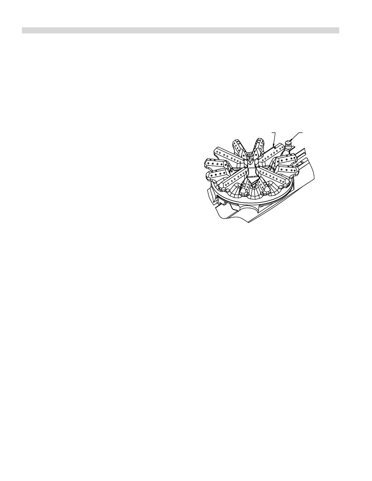
6. When reinstalling the open top burner head be sure
the burner ports are lined up correctly to the pilot. On
the cast burner head there is a raised-arrow indicator to
ensure the burner is installed correctly.
RAISED ARROW INDICATOR
PILOT
7. If an abnormal  ame appears around the edges, it is
usually a sign of grease or dirt in the throat of the burner.
Remove the burner venturi (main body that the burner
heads sit on) to access the air shutter opening. Remove
grease and dirt from the air shutter area carefully. Do
not adjust the shutter setting. The air shutter allows the
proper amount of air to mix with the  ow of gas coming
in from your valve/thermostat ori ce and should not be
adjusted unless by a licensed gas  tter technician.
ABOUT STEPUP HOT PLATE BURNERS: The step up cast
burner housing is assembled at the factory with two locating
pins to ensure that the housing can only be installed in the
correct positions should they be removed for cleaning. One
pin is located on the top of the housing to ensure the burner
head is oriented correctly when installed so that the lighter
nger is correctly pointing at the pilot  ame. The second is
located on the housing bottom and must  t into the slot on
the burner support, otherwise the burner will not be stable.
Cast Iron Top Grates
Cast iron top grate(s) can be cleaned with mild soap and
warm water. For baked on material, a wire brush can be
used. Dry thoroughly. Lightly coat with vegetable oil to help
prevent rust from forming.
MAINTENANCE & CLEANING
Part # 4531237 Rev 2 (09/09/13)
Page 15
MAINTENANCE & CLEANING
Char-Broilers
Establish a regular cleaning schedule. It is necessary to avoid
obstruction between grates and to allow proper combustion
and performance.
1. Broiling grates should be wiped daily while still warm,
using a heavy cloth or other grease absorbing material to
remove grease and burnt food before they burn into the
grid. Remove burnt materials, such as carbonized grease
or food, with a sti wire brush. Do Not use Any Type Of
Steel wool. Small particles may be left on the grid surface
and get into food products.
A common cleaning practice is to turn grates upside
down to burn o the encrusted material. Do not do this
with the radiant broilers! The  ame from the burners is
shielded by a cast iron radiant, which prevents  ame from
reaching the grates. It is likely that cooked-on matter will
cook in even deeper rather than burn o .
2. Broiling grates should be washed thoroughly using a wire
brush and a hot, mild detergent or soap solution. Rinse
with clear, warm water.
3. Dry thoroughly.
4. Immediately after drying, season the top grates lightly
with a non-toxic oil, (liquid vegetable oil or spray oil)
RADIANT BROILERS: Remove the radiants and wire brush
them clean; then wash in hot soapy water. A rule of thumb is
that if the grates are becoming encrusted,so are the radiants.
CERAMIC BRIQUETTE BROILERS: With the cooking grates
removed, turn over all the briquettes and debris will burn o .
5. The front grease trough collects grease via downspout
that empties into the drip tray. Additional grease which
drips past the radiants or ceramic briquettes is also
collected in the same drip tray. The tray must be checked
frequently during operation and drained as necessary.
Spills should be wiped as they occur and at end of each
day the drip tray should be emptied, washed in hot soapy
water., and thoroughly dried before reinstalling.
NOTE: Do not waste gas or abuse equipment by leaving
valves at high temperature settings while not in use.
Throughout all idling periods, set valves at low temperature
setting to keep grids warm. Re-set valves as required for
periods of heavy load. Turn valves to OFF at end of daily
operation. When the broiler is running, never use objects
such as sheet pans to cover the grates in order to hold in heat
in an attempt to burn o grease or other debris.
Stainless Steel
For routine cleaning, wash with a hot water and detergent
solution. Wash just a small area at a time or the water will
evaporate leaving the chemicals behind causing streaking.
Rinse the washed area with a clean sponge dipped in a
sanitizing solution and wipe dry with a soft clean cloth
before it can dry.
Use a paste (of water and a mild scouring powder) if you
have to, but never rub against the grain. All stainless steel has
been polished in one direction. Rub with the polish lines to
preserve the original  nish. Then thoroughly rinse as before.
To prevent  ngerprints there are several stainless steel
polishes on the market that leave an oily or waxy  lm. Do not
use on surfaces that will be in contact with food.
Stainless steel may discolor if overheated. These stains can
usually be removed by vigorous rubbing with a scouring
powder paste.
Use only stainless steel, wood or plastic tools if necessary
to scrape o heavy deposits of grease and oil. Do not use
ordinary steel scrapers or knives, as particles of the iron may
become imbedded and rust. NEVER USE STEEL WOOL.
Either a typical bleach solution or hot water can be used to
sanitize stainless steel.
Part # 4531237 Rev 2 (09/09/13)
Heavy Duty Gas Counter Hot Plates, Griddles, & Char-Broilers
Installation & Operation Manual
Part # 4531237 Rev 2 (09/09/13)
Heavy Duty Gas Counter Hot Plates, Griddles, & Char-Broilers
Installation & Operation Manual
Parte # 4531237 Rev 2 (09/09/13)
  • Page 1 1
  • Page 2 2
  • Page 3 3
  • Page 4 4
  • Page 5 5
  • Page 6 6
  • Page 7 7
  • Page 8 8
  • Page 9 9
  • Page 10 10
  • Page 11 11
  • Page 12 12
  • Page 13 13
  • Page 14 14
  • Page 15 15
  • Page 16 16
  • Page 17 17
  • Page 18 18
  • Page 19 19
  • Page 20 20
  • Page 21 21
  • Page 22 22
  • Page 23 23
  • Page 24 24
  • Page 25 25
  • Page 26 26
  • Page 27 27
  • Page 28 28
  • Page 29 29
  • Page 30 30
  • Page 31 31
  • Page 32 32
  • Page 33 33
  • Page 34 34
  • Page 35 35
  • Page 36 36
  • Page 37 37
  • Page 38 38
  • Page 39 39
  • Page 40 40
  • Page 41 41
  • Page 42 42
  • Page 43 43
  • Page 44 44
  • Page 45 45
  • Page 46 46
  • Page 47 47
  • Page 48 48

Garland M42 M42R M42T M42S Owner Instruction Manual

Category
Barbecues & grills
Type
Owner Instruction Manual

Ask a question and I''ll find the answer in the document

Finding information in a document is now easier with AI

in other languages