Page is loading ...

© LINDY ELECTRONICS LIMITED & LINDY-ELEKTRONIK GMBH - FIRST EDITION (NOV 2007)
U8/16-Modular KVM Switch
with modules:
Cat.5 Extender and IP Access
Modules
User Manual English
LINDY No. 32530, 32531
www.lindy.com
For Commercial Use Only
Tested to comply
with FCC Standards
1
The modular LINDY KVM Switch series U8/16
The U8/16 KVM switch series provides either 8 or 16 KVM server ports
supporting both PS/2 and USB keyboard and mouse connections.
This KVM switch series incorporates a modular concept design which
allows for dual console access. The local console port allows direct
access whilst a second console option permits remote access either via
remote IP or via a remote Cat.5 extender Unit. This option allows
system administrators to access and administrate their servers and
KVM switches from a remote office workstation. The required optional
IP or Cat.5 access modules can be purchased separately and are
simply installed into the back of a U8/16-Modular KVM Switch.
This manual also covers the KVM Switch U8/16-C, another version of
this modular KVM switch series that is used only in conjunction with the
modular LINDY KVM LCD Terminals U8/16-C. U8/16-C models can
only be installed in the back of an appropriate 19” LCD drawer and do
not have a display or front panel controls fitted. Any references to front
panel display and switch buttons in this manual does not apply to the
modular version U8/16-C.
About this manual
This manual is divided into five sections.
•
The first section is an introduction to the U8/16, U8/16-C, U8/16-C5
and U8/16-IP
•
The second section deals with installing and connecting the switch
•
The third section describes the basic operation of the KVM switch
from the locally connected console
•
The fourth section describes operation via the remote Cat.5 Extender
•
The fifth section describes operation and access via remote IP

2
Contents
Section 1.................................................................................. 3
1.1 About the U8/16 concept ...................................................................4
1.2 U8/16-Modular IP Access module: U8/16-IP .....................................4
1.3 U8/16-Modular with Cat.5 Access module: U8/16-C5........................5
1.4 KVM compatibility and backward compatibility with P-series KVMs ..5
1.5 Product Features ...............................................................................6
1.6 Package Contents .............................................................................7
1.7 Optional Cables and Accessories (not included) ...............................7
Section 2.................................................................................. 8
2.1 Product Information & Connection Guide ..........................................9
2.2 Rackmount Installation ......................................................................10
2.3 Cascading / Daisy Chaining of multiple KVM Switches .....................10
Section 3.................................................................................. 12
3.1 KVM Switch Operation.......................................................................13
3.2 Keyboard Hotkey Selection ...............................................................15
3.3 On Screen Display Menu (OSD) Port Selection.................................17
Section 4.................................................................................. 19
4.1 Cat.5 KVM Extender Features...........................................................20
4.2 Cat.5 KVM Extender Installation........................................................20
4.3 Cat.5 KVM Extender Operation .........................................................21
Section 5.................................................................................. 22
5.0.1 KVM over IP Access Features .....................................................23
5.0.2 KVM over IP Module Installation...................................................23
5.1 Configuration .....................................................................................24
5.2 U8/16-IP Setup Tool ..........................................................................25
5.3 Keyboard, Mouse and Video Configuration .......................................27
5.4 Usage ................................................................................................30
5.5 Logging In..........................................................................................31
5.6 Navigation..........................................................................................32
5.7 Menu Options ....................................................................................39
5.7.1 Remote Control.............................................................................39
5.7.2 Virtual Media.................................................................................42
5.7.3 User Management ........................................................................50
5.7.4 KVM Settings ................................................................................52
5.7.5 Device Settings.............................................................................57
5.7.6 Maintenance .................................................................................70
Troubleshooting...................................................................... 74
Key Codes ............................................................................... 76
3
Section 1
Introducing
the U8/16

Section 1 Introducing the U8/16-IP
4
1.1. About the U8/16 concept
The U8/16 series KVM switch supports traditional PS/2 mouse and keyboard connections as
well as modern USB connections. The U8/16 series supports the following computer platforms,
PC, Mac and SUN.
Combined KVM cables are used to connect the servers to the KVM switch’s computer ports.
Connections to the servers use a traditional VGA connector, one PS/2 mouse connector and
one USB mouse & keyboard connector. To connect a server via USB only the PS/2 connector is
not used; to connect the server via PS/2 the green PS/2 mouse connector is plugged into the
servers mouse port and a special USB to PS/2 keyboard adapter is attached to the USB cable
and then plugged into the server’s PS/2 port.
The U8/16 series KVM switch introduces a modular concept for dual console operation. In
addition to the local console port the switch also offers a secondary remote access option either
via IP or via a remote Cat.5 extender unit. Using this method, system administrators are able to
access and administrate their servers and KVM switches from a remote office workstation.
Depending on your application the appropriate optional access modules can be purchased
separately and are simply installed into the back of the U8/16-Modular KVM Switch.
This advanced 8/16 port KVM switch allows direct control of up to 16 computers from a single
KVM (Keyboard, Video, and Mouse) console. The switch can also be daisy chained with further
KVM Switch U8/16 to control up to 128 servers/workstations from 8 daisy chained 16 port KVM
switches.
Three methods of switching between the connected computers are available: 1. by pressing the
front panel push buttons; 2. by using keyboard hotkeys; or 3. via OSD (On Screen Display).
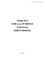
1.2. U8/16-Modular with IP Access module: U8/16-IP
KVM over IP technology allows a simple web browser interface to be used to access the switch
and the connected computers via a local area network (LAN) or, when connected to a wide area
network (WAN), access to the switch and the connected computers can be achieved from
almost anywhere in the world.
IP Network
Multiple Servers
U8/16-IP
Local Console
Remote Access
Remote & local control of multiple computers
Section 1 Introducing the U8/16-IP
5
The U8/16-IP provides a non-intrusive solution for remote access and control because the
software runs on its embedded processors only, so there’s no interference with computer
operation, or impact on network performance. The U8/16-IP also features remote mass storage
support; a USB connection from the switch to one of the connected computers allows virtual
storage to be set up on the host and accessed from the client.
1.3. U8/16-Modular with Cat.5 Access module: U8/16-C5
If the Cat.5 KVM Extender module is installed it will allow remote access to the KVM switch
U8/16 and its connected servers via a dedicated Cat5e/6 RJ45 cable with a maximum length of
up to 100m @ 1024 x 768. The remote console consists of a Cat.5 Extender receiver unit which
is situated at the remote administrator’s desk. The remote receiver unit also includes a KVM
switch function which allows the administrator to either work on his local workstation or
alternatively switch to access the KVM switch and its connected servers.
The Cat5e/6 KVM Extender provides real time access without any signal conversion and
delays, whilst the IP Access module converts the VGA and keyboard/mouse signals into a
TCP/IP data stream and sends them via the LAN/WAN connection to the remote user. The
performance of the IP access connection and response time will vary depending upon available
bandwidth and traffic throughput.
1.4. KVM compatibility and backward compatibility with
LINDY P-series KVM switches
The U8/16 series KVM switches are compatible with almost any KVM switches using
STANDARD VGA, keyboard and mouse signals. The U8/16 is also compatible with older LINDY
P-Series KVM switches. Please note compatibility is only provided via the server ports of the
U8/16 series KVM switch but not via the daisy chain ports! Therefore when customers are
willing to mix U- and P-series KVMs (or other brand KVMs) it has to be done via port cascading
because daisy chain configuration of mixed U- and P-series KVMs cannot work. When using the
port cascading the main hotkey of the U-series KVM has to be changed (to an available hotkey
from the KVM OSD menu) so it will not conflict with the SCROLL LOCK hotkey of the P-series
KVMs or third party KVM switches.

Section 1 Introducing the U8/16-IP
6
1.5. Product Features
8/16 port KVM switch in a 1U, 19” rackmount size design
Built-in daisy chain port allows daisy chaining of up to 8 LINDY KVM switches U or P series
to be connected to support up to 128 computers
Local console operation plus optional KVM over IP or KVM over Cat.5 control
Remote mass storage device support for KVM over IP access for version U8/16-IP
Supports all commonly used operating systems
Support for PC, Mac and Sun computers with USB ports
Hot Plug Support - add or remove computers and KVM switches for maintenance without
powering down the switch or the connected computers
High Quality Video – Local console supports display resolutions of up to 1920x1440
No Software Required for local or Cat.5 KVM access - easy PC selection via On Screen
Display Menu, Push Buttons or Keyboard Hot Keys
Provides various Hotkeys (Scroll-Lock/ Caps-Lock/ Num-Lock/ L-Alt/ L-Ctrl/ L-Win/ R-Alt/ R-
Ctrl/ R-Win) for switching computer port and other control functions
Integrated password security protection for up to 8 users + admin with access control list
restrictions for the users
Eight character password protection and search function for server name
Remote IP enterprise security architecture, password protected using encrypted data
transmission either via secured web browser session
Auto Scan Mode for monitoring computers with adjustable scan time from 5~99 seconds
Keyboard status is automatically restored when switching between computers
LED Display for easy status monitoring
Buzzer sound for port switching confirmation
Uses special single connector USB/PS/2 + VGA KVM cables with 15 Way Hi-Density
connectors at the KVM Switch end
Maintains continuous keyboard and mouse emulation
Section 1 Introducing the U8/16-IP
7
1.6. Package Contents
LINDY KVM Switch U8/16 modular KVM switch
Power Adapter
19” Rackmount Kit
KVM Daisy Chain Cable
Utility & Manual CD
Printed Quick Start Guides
1.7. Optional Cables and Accessories (not included)
This KVM switch requires a standard VGA monitor, USB keyboard and mouse for direct
connection to the local console port.
To connect each individual computer to the switch, you will need to purchase special LINDY
KVM system cables as listed below. If the connected computers are PS/2 only then you can use
the PS/2 version P16 and P-XT/-IP series system connection cables.
To connect a USB computer you will require an additional PS/2 female to USB male adapter
available as LINDY part No. 70510.
U8/16, P16, P8/16XT, P16-IP series KVM Cable with PS/2 only
o 1m LINDY No. 32510
o 2m LINDY No. 32506
o 3m LINDY No. 32507
o 5m LINDY No. 32508
U8/16 series PS/2 keyboard female to USB male adapter LINDY No. 70510
Daisy Chain Cable (included)
One special HD-15 system KVM daisy chain cable with all pins connected is included with the
switch. This cable must be used to daisy chain multiple U-series KVM switches – standard VGA
cables may not work correctly as not all cables support all pins connected.
U8/16 KVM Cable (15 Way HD Male to 15 Way HD Male + 2x PS/2 Male) + USB Adapter
+ Adapter keyboard
PS/2 female
USB A male

8
Section 2
Hardware
Installation
Section 2 Hardware Installation
9
2.1. Product Information & Connection Guide
Make your connections to the switch as detailed below.
Ensure all devices are switched off before connecting. Once all connections have been made,
power on the switch, your monitor, and then the connected computers in that order.
Optional remote access Cat.5 or IP module installation
If you want to use an optional remote access Cat.5 or IP module, please install it in the slot at
the rear of the switch prior to powering up the switch and the connected computers.
Port Select Button
Used for direct port selection. To access ports 1 to 8 simply
press the button; for ports 9 to 16, press the ‘↵
↵↵
↵’ button on the
front panel and the required port button simultaneously.
Port LED Display
When the LED labelled ‘P’ is illuminated green a computer attached to this port is
powered on. When the LED labelled ‘
S’ is illuminated red, the KVM console is connected
to this port. If this LED flashes, the console is connected to this port, but either no
computer is attached, or the attached computer is not switched on.
Shift Button
This button allows ports 9 to
16 to be selected.
Bank Select Button
Pressing this button switches ‘banks’ and allows the computers connected
to ‘slave’ switches in a cascaded installation to be selected. The LED
above will display the selected bank. Pressing this button at the same time
as the port 8 button resets the switch.
Local Console Ports
Connect your USB keyboard, VGA monitor and
USB mouse here. (Not for models U8/16-C)
Computer Connection Ports
You can connect up to 16 computers to these ports using dedicated KVM
cables. ‘PC1’ refers to the first port, ‘PC2’ to the second and so on...
Daisy Chain Ports
Allows a slave U-
Series KVM switch to be connected
to the U8/16 using a special KVM daisy chain cable.
Power Connection
Connect the supplied power adapter here.
Although the computers connected to the switch
may be able to supply enough power to the unit,
erratic operation may occur if the power supply is
not used.
Cat.5 Extender Port (only when
equipped with Cat.5 KVM Extender Module!)
Use an appropriate length RJ45 cable to connect to the remote
Cat.5 KVM Extender Receiver unit at the remote location.
This module port may be equipped either with Cat.5 or IP remote
access module or remain empty.

Section 2 Hardware Installation
10
2.2. Rackmount Installation
Before you start installation please verify that all
parts are included according to the package
contents.
If you want to install the KVM Switch in a 19” server
rack please attach the enclosed 19” rackmount
brackets using the screws provided.
2.3. Cascading / Daisy Chaining of multiple KVM Switches
At the time this manual was written (September 2007) the U8/16 KVM switch range may be
cascaded with other LINDY U-Series KVM switches only. Later versions of the new C5-8/16
series KVM switches will be introduced that will also be daisy chainable with the U series.
All other brands and models of KVM switches may be cascaded with LINDY U-series KVM
switches via the computer ports 1-16 of the U-series KVM switch.
To connect an additional SLAVE switch to the MASTER (or previous) switch, you must use the
included special KVM system daisy chain cable. Standard VGA cables may not work correctly
as not all cables support all pins connected.
Step 1 - Connect the local console
Connect your keyboard, mouse and monitor to the console ports of the U8/16 MASTER KVM
Switch.
Step 2 – Connect the first Slave
Use the daisy chain cable to connect the daisy chain port of the MASTER/previous KVM
Switch and the other end to the local console port of the next SLAVE switch.
Step 3 – Cascading / Daisy chaining
Repeat the previous step to daisy chain mores switches. Each individual switch in the chain
represents a different Bank. The MASTER switch is Bank 1 and each cascaded SLAVE follows
on as Bank 2, 3, 4 etc. You may cascade a maximum of eight switches/banks.
Bank 1 (Master)
Bank 3... to a maximum of 8
Cascading KVM Switches
by daisy chaining
Section 2 Hardware Installation
11
Step 4 – Resetting the Switches
After you have connected and switched on the SLAVE switches and computers, all of the KVM
switches may need to be reset. First, reset the SLAVE switch at the end of the daisy chain and
then reset all of the other SLAVE switches up to the MASTER U8/16 switch.
To reset the switch, press and hold the Bank button and port 8/16 button on the front panel of
the switch.
Each SLAVE switch should now show a dash in its BANK display.
Now, reset the MASTER switch - it will show a 1 in the BANK display. Each SLAVE switch
BANK display will now change to a number according to its position in the daisy chain.

12
Section 3
KVM Switch
Operation
Section 3 KVM Switch Operation
13
3.1. KVM Switch Operation
3.1.1. Password Security
When you power on the U8/16 it will ask you for a user name and a password. The default
user name and default password for both is eight zeros –“00000000”. Please key in eight
zeros in the password field. You may use the “0” from the standard keypad but not from the
numeric keypad.
Note: Please don’t change the password until you are familiar with the operation of the OSD
menu – i.e. keep the default password “00000000”. Otherwise, if you forget the password, you
will need to send the switch back to LINDY for maintenance to clear the password.
The U8/16 OSD security feature offers up to 8 users + 1 SUPERVISOR.
A user specific access control list is available from the OSD of the KVM switch and can be
configured by the supervisor.
3.1.2. Hot Plug Support
The U8/16 supports a “Hot Plug” function for easy addition or removal of computers. The user
can arrange or maintain the computers and daisy chained KVM Switches as follows:
a. A computer can be disconnected and reconnected to the same or a different port of the KVM
switch without having to power it off as long as it is currently not connected to the console. In
most cases the PS/2 mouse and keyboard signals will be maintained and will not be lost.
b. The mouse driver of the computer has to support the hot plug function or the computer may
need to be rebooted when it is reconnected.
c. You can unplug your mouse or keyboard from the console port and plug it back in at any
time. You should not use different types of mice when performing this.
d. A SLAVE KVM switch can be added or removed at any time, but after adding or removing a
switch it may be required to reset all of the KVM switches. But you DO NOT need to reboot
the computers.
Please note: Some Operating Systems such as certain Unix versions are unable to
support the “Hot Plug” function. If you Hot Plug when using this kind of O.S., it may cause
unpredictable operation or may shut down the computer. Before attempting to use the Hot
Plug feature, please check that the O.S. and mouse driver support this function.
Important note:
Your monitor will only display one PC signal at any one time. All
keyboard and mouse commands are sent to this PC only. After initial power up, port 1 is
active by default.
When a PC is connected to the currently selected port and it is not switched on,
or is in sleep mode, the monitor will not display any signal.

Section 3 KVM Switch Operation
14
3.1.3. Computer / Port Selection
You can select the computer you want to access in one of three different ways:
Front panel push button selection
Keyboard hotkey selection
On screen display menu selection
3.1.4. Port LED Display
The front panel of the switch has two LEDs for each port.
When the LED labeled “P” is illuminated GREEN a computer attached to this port is powered
on. When the LED labeled “S” is illuminated RED, the KVM console is connected to this port. If
this LED flashes, the console is connected to this port but either no computer is attached, or the
attached computer is not switched on.
3.1.5 Front panel push button selection
You can select a computer by pressing the appropriate port push button. Each push button
refers to two ports. To access ports 1 to 8 simply press the button; to access ports 9 to 16 you
must push the button marked “
↵
↵↵
↵
” and the required port button simultaneously.
For cascaded KVM Switches you can ONLY use the port selection push buttons on the
MASTER U8/16 Switch to switch the SLAVES. You may also switch via OSD or keyboard
hotkey.
Section 3 KVM Switch Operation
15
3.2. Keyboard Hotkey Selection
You can also conveniently select the computer to be accessed and displayed by switching ports
through simple keyboard key sequences. To send commands to the KVM switch, the “SCROLL
LOCK” key must be pressed twice within 2 seconds. You will hear a beep to confirm that
the keyboard is in hotkey mode. If you have not pressed any key in hotkey mode within 2
seconds, the keyboard will return back to Operating System control status.
For the U-series KVM switches it is possible to change the “SCROLL LOCK” hotkey to certain
other hotkeys by selection from the OSD menu. This can help to prevent hotkey collisions with
other hotkeys from other devices. To do so you have to enter the Main OSD Menu by typing
SCROLL LOCK twice and then pressing the SPACEBAR within 2 seconds.
To invoke the On Screen Display Menu press the following hotkeys:
+ + = On Screen Display Menu
If the KVM switch prompts for your user name and password while no user names and
passwords have been assigned you may use eight zeros “00000000” for each, user name and
password.
Select F1: MAIN from the MAIN OSD Menu and then 06 HOTKEY to go to the hotkey selection
menu. Select any of the available hotkeys: Scroll Lock / Caps Lock / Left Ctrl / Right Ctrl / Left
Alt / Right Alt / Left Win / Right Win. Confirm your selection by pressing the ENTER key. From
now on the new hotkey is permanently changed.
Direct Port Selection / Keyboard Hot Key Commands:
Within 2 seconds
+ + = Previous Port
or
+ + = Next Port
Please note: If you change the default hotkey always remember to enter the new hotkey!
PORT NAME
Scroll
Lock
Scroll
Lock
Tip: Hold the arrow key down, or
press multiple times, to cycle
through the ports
BANK: 1
01
SYSTEM 01
02
SYSTEM 02
03
SYSTEM 03
04
SYSTEM 04
05
SYSTEM 05
06
SYSTEM 06
07
SYSTEM 07 USER :
SUPERVISOR
F1 : MENU
F2 : LOGOUT
ESC : QUIT
ENTER: COMPLETE
08
SYSTEM 08
/
: SELECT PORT
PgDn/PgUp: BANK SELECT
SCAN TIME
10 SEC. FW1V3
Scroll
Lock
Scroll
Lock
Space Bar

Section 3 KVM Switch Operation
16
KVM Switch / Bank Selection:
The U8/16 supports daisy chaining of up to 8 KVM Switches (Banks). Therefore, when using
direct hotkey port selection you must include the key sequence for the KVM Switch/Bank:
+
+
+
Example: To access a computer attached to Port 6 of the first KVM Switch you should
press the following hotkeys:
+
+
+
+
To use hotkey switching to access another KVM Switch / Bank:
+ + = Previous Bank
+ + = Next Bank
Auto Scan mode:
+ + =
Auto Scan, Supervisor only
(Press any key to exit Auto Scan Mode)
Please note: If you change the default hotkey always remember to enter the new hotkey!
Available hotkey commands:
Command Action
Space bar Enter into OSD Main Menu
101 ………… 816 Bank + port number direct selection
P user / supervisor log out
U SUPERVISOR only: turn Security function ON / OFF. If security is OFF
no password login is required and Access Control list is disabled!
R SUPERVISOR only: Set the OSD back to factory default. Except User
Security settings.
Scroll
Lock
Scroll
Lock
Bank
No 1~8
Port No.
01~04 (4 port)
01~08 (8 port)
01~16 (16 port)
Important Note:
Always keep in
mind to include
leading zeros for
all ports below 10!
i.e.104 for Port 4 of
the first switch.
Bank no. and
Port no. selection
must be made
using the
numeric keys on
the keyboard.
Keys on the
numeric keypad
are not available
as hot key
commands!
Scroll
Lock
Scroll
Lock
Scroll
Lock
Scroll
Lock
Page
Up
Page
Down
(
This will only work if a daisy
chained KVM Switch is present)
Scroll
Lock
Scroll
Lock
1 0 6
Scroll
Lock
Scroll
Lock
S
Section 3 KVM Switch Operation
17
1 0 2 SYSTEM 01
Scroll Lock
3.3. On Screen Display Menu (OSD) Port Selection
The On Screen Display menu provides a lot of information about the U8/16 and the attached
computers, and offers advanced administration features and full KVM Switch control to the user.
When you have logged into the KVM switch with your password a STATUS OSD display will be
displayed:
System 02 :
102 = Bank 1, Port 02 System = PC name
Scroll Lock = recent hotkey 02 = selected port
Auto-LOGOUT function
• During normal operation if no input from the keyboard or mouse is made for a period of 10
minutes the KVM switch will turn off the display. It will display the Login window asking for
user name and password – as long as password security is not disabled - upon the next
keyboard or mouse entry. After a minute of keyboard/mouse inactivity the monitor will be
turned off (you may notice the monitor LED turning from green to orange color).
You now can enter the OSD Main Menu by typing the hotkey twice followed by SPACEBAR.
Using the cursor keys you now can toggle through the ports / computers connected on bank 1
and select any by pressing the ENTER key. Please note that the
symbol indicates all active
computers connected to the ports. Computers connected to ports not showing this symbol may
be either switched off or in standby / power down mode. If you switch to any of these ports then
you will not have a video signal displayed and will have to boot or wake up the connected
computer. To access ports 9…16 simply scroll down with the cursor key below port 8.
To select any slave KVM switch select its bank number by pressing the Page Up / Down keys.
The appropriate bank number will then be displayed on the left hand side near top and the
connected computers to this slave KVM switch can be selected.
Or you can access any of the further OSD configuration menus from the right side of the main
menu by typing the F1 command key. ESC quits from the OSD. F2 logs you out, either from
the OSD only if no password security is disabled or totally into Logon screen if password
security is enabled. F2 logout is only available from the main OSD menu.
PORT NAME
BANK: 1
01
SYSTEM 01
02
SYSTEM 02
03
SYSTEM 03
04
SYSTEM 04
05
SYSTEM 05
06
SYSTEM 06
07
SYSTEM 07 USER :
SUPERVISOR
F1 : MENU
F2 : LOGOUT
ESC : QUIT
ENTER: COMPLETE
08
SYSTEM 08
/
: SELECT PORT
PgDn/PgUp: BANK SELECT
SCAN TIME
10 SEC. FW1V3

Section 3 KVM Switch Operation
18
The OSD Menu displays further OSD configuration menus when selecting F1 from the main
OSD menu.
From the F1 Menu further submenus can be selected to configure the switch settings. In the
submenus you can either use the cursor up/down keys or the mouse for navigation or simply
press the number of the further option menu. You can go one layer back by clicking on the
symbol with the mouse. ESC key quits the OSD completely.
Select 01 LANGUAGE – for Supervisor only – to set the
OSD language to either: English, French, German, Italian,
Spanish, Japanese, Chinese or Russian.
Select 02 PORT NAME EDIT – for Supervisor only – to
change / assign names to the computers attached to the
appropriate ports. The names can be up to 10 characters
long, all upper case.
Select 03 PORT SEARCH – all users – to search for any
computer name as assigned. If you type only a few
characters, all computers and ports will be displayed that
contain the typed characters.
Select 04 USER SECURITY – for Supervisor only – to
assign the Supervisor password and users and their
passwords. For both up to 8 characters can be used.
Select 05 ACCESS LIST – for Supervisor only – to assign access restrictions to users for
certain ports. Default setting is no access restriction. To disable a user from access to a certain
port go to the appropriate user and port and select the option with the ENTER key. The sign in
the matrix list will change from 0 to X to indicate the access restriction.
Select 06 HOTKEY – for Supervisor only – to change the hotkey to any of the following: Scroll
Lock / Caps Lock / Left Ctrl / Right Ctrl / Left Alt / Right Alt / Left Win / Right Win. This hotkey
will be permanently changed.
Select 07 TIME SETTINGS – for Supervisor only – to set the Autoscan time interval from 5
seconds up to 99 seconds.
Select 08 OSD MOUSE – for Supervisor only – to set the speed of the mouse movement in
OSD menu. There are 3 choices: slow, medium and fast. Use the appropriate setting for your
mouse.
You can close almost any OSD window by simply pressing the ESCAPE key.
User and supervisor can only log out via OSD menu when pressing F2 key.
MAIN MENU
X
SELECT OPTION
01 LANGUAGE
02 PORT NAME EDIT
03 PORT SEARCH
04 USER SECURITY
05 ACCESS LIST
06 HOTKEY
07 TIME SETTINGS
08 OSD MOUSE
19
Section 4
Cat.5 Extender
Access
& Operation

Section 4 CAT. 5 Extender Access & Operation
20
4.1. Cat.5 KVM Extender Features
The modular KVM switch U8/16 offers the option to use it with or without a remote console
access module. This module may either be a Cat.5 Extender or IP Access solution.
The Cat.5 Extender solution provides real time KVM access via a dedicated Cat5e/6 cable with
a maximum length of 300m. When using higher resolutions we suggest the following maximum
pixel resolution versus length: 1600x1200@75m/ 1280x1024@150m/1024x768@250m
Overall picture quality when using the Cat.5 extender will depend on the Cat.5/5e/6 cable
quality and also on the signal quality generated by the graphics card used. To optimize the
picture quality high quality amplifiers, equalizers and an auto skew compensation circuits are
used in the Cat.5 Receiver unit to compensate for the attenuation and for the different lengths of
the individual twisted pairs inside long Cat.5/5e/6 cables.
In comparison to the IP Access Extender solution the Cat.5 Extender provides a real time
analog KVM signal. And the Cat.5 KVM Extender does not require any software for operation as
it just operates as an analog KVM signal extender.
The Cat.5 KVM Extender module consists of two units: The local Cat.5 Extender Transmitter
module fitted into the KVM Switch slot and the remote Cat.5 Extender Receiver unit installed at
the remote user’s location.
The remote Cat.5 Extender Receiver unit includes a local KVM switch which allows the remote
user to also connect a local workstation to the receiver unit and switch between the local
workstation and remote KVM Switch access.
4.2. Cat.5 KVM Extender Installation
Before you install the local Cat.5 Extender Transmitter module into the KVM switch ensure all
connected computers are switched off and the power supply is unplugged. Proceed to unscrew
and remove the small metal cover on rear of the KVM switch. Carefully slide the module into the
slot and secure in place with the screw previously removed.
Now install the remote Cat.5 Extender Receiver unit at the remote user’s location. You will need
a VGA monitor and a USB mouse and keyboard to connect to the receiver unit. Connect your
local workstation to the receiver unit if required using the dedicated KVM system cable included
with the Cat.5 KVM Extender. Finally connect the Cat.5/5e/6 cable and the power supply unit.
The KVM cable provided can be used to connect either PS/2 or USB equipped computers in the
same way as previously described for connecting computers to the KVM switch in section 1.6.
A dedicated Cat5/5e/6 cable with RJ-45 connectors is required to connect the Receiver unit and
the Extender module located in the KVM switch. This connection must not be made via a “Live”
Ethernet connection but only via multiple cable segments using patch cables, patch panels and
wall sockets. Please consider the maximum resolution versus length limitations as mentioned
previously. Please also try to limit the number of connections between the transmitter and
receiver unit as this will help to reduce any signal loss introduced.
You may now proceed to power up all connected equipment and check for correct operation.
Section 4 CAT. 5 Extender Access & Operation
21
4.3. Cat.5 KVM Extender Operation
The Cat.5 Extender Receiver unit incorporates its own OSD menu which allows switching
between the local workstation and remote KVM Switch as well as configuration of the unit.
To invoke the hotkey and OSD operation of the Cat.5 Receiver unit simply press the hotkey
(factory default setting is Caps Lock) twice and press any other command from the list below
within 2 seconds:
Command Action
F1 Selects the OSD Help Menu of the receiver unit
F2 Selects the OSD Hotkey setting menu of the receiver unit
C Toggle between local workstation and remote KVM switch access
Q Turn ON / OFF the beep confirmation sound of the receiver unit
S Turn ON Autoscan functions of the receiver unit. Display will switch at 5
second intervals between the local workstation and the KVM switch
Press any key to stop scanning
A Auto adjusts the amplifiers and equalizers of the remote Cat.5 Extender
receiver unit. This auto adjustment is also performed automatically each
time the receiver unit is powered on
To change the default hotkey simply activate the local OSD F2 menu. Choose a new hotkey by
typing in the appropriate number key as listed in the local OSD F2 menu.
The following hotkeys are available: Scroll Lock / Caps Lock / Left Ctrl / Right Ctrl / Left Alt /
Right Alt / Left Win / Right Win. When choosing a new hotkey try to avoid using a hotkey
already used by any connected KVM switches as conflicts may arise when switching ports.

22
Section 5
IP Access
Configuration
& Operation
Section 5 IP Access Configuration & Operation
23
5.0.1. KVM over IP Access Features
The IP access module provides remote KVM over IP access to the KVM switch U8/16. It
converts all keyboard video and mouse signals and sends them as TCP/IP signals over your
LAN/WAN connection. The KVM switch U8/16 may be accessed from any computer connected
to your network and provides full KVM access including BIOS level access to all the connected
computers.
Please note that KVM over IP does not operate in a “real time” environment and that some
degree of time delay will occur due to limiting factors such as available bandwidth and network
traffic.
The KVM over IP Access module can be accessed via a simple web browser and via dedicated
software tools included with the product. It uses secure encrypted sessions and password
authentication protocols.
Please note that the conversion of video, mouse and keyboard signals requires a certain
amount of CPU processing time. Transporting large amounts of data over TCP/IP requires a
high bandwidth connection. Limited bandwidth may restrict or limit the possible screen
resolutions and colour depths which can be transmitted over your LAN / WAN.
A connection which exhibits limited bandwidth will result in slower mouse reaction and cursor
control. Also the available screen resolution, colour depth and refresh rates will also be affected.
Ensure the connection you are using provides adequate bandwidth, some adjustment of screen
resolution, colour depth and mouse cursor control may have to be made for satisfactory
operation.
5.0.2 KVM over IP Access Module Installation
Before you install the IP Access module into the KVM switch ensure all connected computers
are switched off and the power supply is unplugged. Proceed to unscrew and remove the small
metal cover on rear of the KVM switch. Carefully slide the module into the slot and secure in
place with the screw previously removed.
You may now proceed to power up all connected equipment and check for correct operation.
For the remainder of this manual the U8/16 KVM switch with installed KVM
over IP Module will be referred to as U8/16-IP.

Section 5 IP Access Configuration & Operation
24
5.1. Configuration
The U8/16-IP’s communication interfaces
are all based on TCP/IP. The switch comes
pre-configured with the following IP
configuration shown here:
If this initial configuration does not meet your requirements, the following section describes the
configuration that is necessary to access the U8/16-IP for the first time.
Initial Configuration via a DHCP Server
By default, the U8/16-IP will try to contact a DHCP server in the subnet to which it is physically
connected. If a DHCP server is found, it will provide a valid IP address, gateway address and
subnet mask. If a DHCP server is not available then you will need to assign a fixed IP
assignment to the MAC address of the IP Access Module. You can find the MAC address
details on the printed label on the underside of the IP Access module.
Before you connect the device to your local subnet, be sure to complete the corresponding
configuration using the setup tool supplied on the CD ROM. Follow the procedure described on
the next page (Section 5.2)
Initial Configuration via a Serial Console
The U8/16-IP has a serial line interface (host side)
for connecting a serial terminal. This connector is
compliant with the RS-232 serial line standard. The
serial line has to be configured with the parameters
given in this table:
When configuring with a serial terminal, reset the U8/16-IP and immediately press the ESC key.
You will see some device information and a “=>” prompt. Type config and press the Enter key.
Wait a few seconds for the configuration information to appear.
As you proceed, the following questions will appear on the screen. To accept the default values
(shown in square brackets below) press the Enter key.
IP auto configuration (non/dhcp/bootp) [dhcp]:
IP [192.168.1.22]:
Net mask [255.255.255.0]:
Gateway (0.0.0.0 for none) [0.0.0.0]:
Parameter Value
IP auto configuration DHCP
IP-Address -
Net-mask 255.255.255.0
Default-Gateway none
Parameter Value
Bits/second 115200
Data bits 8
Parity No
Stop bits 1
Flow Control None
Note: If the DHCP connection fails on boot-up, the U8/16-IP will not be assigned an
IP
address.
Section 5 IP Access Configuration & Operation
25
5.2 U8/16-IP Setup Tool
MAC Address Detection
Connect the U8/16-IP to your computer either via a local network, or via USB. If you use a USB
connection Windows will detect the U8/16-IP as a ‘Removable Disk’ and an appropriate drive
letter will be assigned.
Start the setup tool from the CD ROM.
A window opens as shown below:
On the upper left corner, the MAC address of the U8/16-IP is displayed. To re-detect the MAC
address, press the Refresh Devices button. The displayed MAC address should correspond to
the printed address shown on the label on the base of the IP module.
On the lower right corner of the window, there are two buttons: Query Device and Setup
Device. Press the Query Device button to display the preconfigured values of the network
configuration. The values are displayed in the text fields located above. If necessary, adjust the
network settings to your needs. To save the changes enter a user login and a password (see
Authentication, below) and then press the Setup Device button.

Section 5 IP Access Configuration & Operation
26
Authentication
To adjust the authentication settings, enter your login as a super user and change your
password.
Super user login
Enter the login name of the super user. The initial value is "super". All of the characters are
lower case.
Super user password
Enter the current password for the super user. This initial value is "pass". All of the characters
are lower case.
New super user password
Enter the new password for the super user.
New password (confirm)
Re-type the new password for the super user.
To close the window and accept the changes, press the OK button, otherwise press the Cancel
button.
IP Auto Configuration
With this option, you can specify whether the U8/16-IP should obtain its network settings from a
DHCP or BOOTP server. From the drop down list select either DHCP or BOOTP. If you select
NONE, the IP auto configuration is disabled and you should manually input the following
network settings:
IP address
The IP address the U8/16-IP uses.
Net mask
The net mask of the connected IP subnet.
Gateway address
The IP address of the default router for the connected IP subnet. If you do not have a default
router, enter 0.0.0.0.
Section 5 IP Access Configuration & Operation
27
5.3. Keyboard, Mouse and Video Configuration
Between the U8/16-IP and the host, there are two interfaces available for transmitting keyboard
and mouse data: USB and PS/2. The correct operation of the remote mouse depends on
several settings which will be discussed in the following subsections. Please see page 34 for
details of how to make the specific changes to the mouse settings described below.
U8/16-IP Keyboard Settings
The U8/16-IP settings for the host's keyboard type have to be correct in order to make the
remote keyboard work properly. The settings can be checked using the U8/16-IP front-end,
please see page 37 for details of how to make changes to the keyboard settings.
Remote Mouse Settings
A common problem with KVM devices is the synchronization between the local and remote
mouse cursors. The U8/16-IP addresses this problem with an intelligent synchronization
algorithm. There are two mouse modes available on the U8/16-IP: Auto mouse speed and
Fixed mouse speed.
Auto mouse speed
The automatic mouse speed mode tries to detect the speed and acceleration settings of the
host system automatically. Speed detection is performed during mouse synchronization. If the
mouse does not move correctly, there are two ways to re-synchronize the local and remote
mouse:
Fast Sync: Fast synchronization is used to correct a temporary, but fixed skew. Choose this
option using the Remote Console options menu or by pressing the mouse synchronization
hotkey sequence - [ALT] + [F12]
Intelligent Sync: If the fast sync does not work correctly or the mouse settings have been
changed on the host system, you can use the intelligent resynchronization option. This method
can be accessed from the Mouse Handling sub menu of the Remote Console Option menu.
Intelligent synchronization requires a correctly adjusted picture. Use the auto adjustment
function or manual correction in the Video Settings panel to setup the picture. The Sync mouse
button on top of the Remote Console can behave differently, depending on the current
state of mouse synchronization. Usually pressing this button leads to a fast sync, except in
situations where the KVM port or the video mode was recently changed.
Fixed mouse speed
This mode just translates the mouse movements from the Remote Console in a way that one
pixel move will lead to ‘n’ pixel moves on the remote system. This parameter ‘n’ is adjustable.
However, it should be noted that this works only when mouse acceleration is turned off on the
remote system.
Tip: When first started, if the local mouse pointer is not synchronized with the remote mouse
pointer, click the Auto Adjust Button once. If the mouse is still not synchronized select
Intelligent Sync from the Mouse Handling sub menu of the Remote Console Option menu.

Section 5 IP Access Configuration & Operation
28
Host System Mouse Settings
The host's operating system obtains various settings from the mouse driver.
Special Mouse Driver
There are mouse drivers which influence the synchronization process and lead to
desynchronized mouse pointers. If this happens, make sure you do not use a special vendor-
specific mouse driver on your host system.
Windows XP Mouse Settings
If using Windows XP, disable the enhance pointer precision setting.
Active Desktop
If the Active Desktop feature of Microsoft Windows is enabled, do not use a plain background.
Instead, use some kind of wallpaper. Alternatively, you could also disable the Active Desktop
completely.
Navigate your mouse pointer into the upper left corner of the applet screen and move it back
and forth slightly. In this way the mouse will be resynchronized. If re-synchronizing fails, disable
mouse acceleration and repeat the procedure.
Single and Double Mouse Mode
The information above applies to Double Mouse Mode, where both remote and local mouse
pointers are visible and need to be synchronized. The U8/16-IP also features another mode -
Single Mouse Mode, where only the remote mouse pointer is visible. Activate this mode in the
open Remote Console and click into the window area. The local mouse pointer will be hidden
and the remote one can be controlled directly. To leave this mode, use the hotkey combination
[ALT] + [F12] to free the captured local mouse pointer.
Note: The following limitations do not apply when using USB mice and
Windows 2000 and higher!
Section 5 IP Access Configuration & Operation
29
Recommended Mouse Settings
For the different operating systems we can give the following advice...
MS Windows 2000/2003 (Professional and Server), XP
In general, we recommend the use of a USB mouse. Choose USB without Mouse Sync. For a
PS/2 mouse choose Auto Mouse Speed. For XP disable the option called enhance pointer
precision in the Control Panel.
SUN Solaris
Adjust the mouse settings either via xset m 1 or use the CDE Control Panel to set the mouse to
1:1, no acceleration. As an alternative you may also use the Single Mouse Mode.
MAC OS X
We recommend using the Single Mouse Mode.
Video Modes
The U8/16-IP switch recognizes a limited number of common video modes. When running X11
on the host system, please do not use any custom mode lines with special video modes. If you
do, the U8/16-IP switch may not be able to detect them. We recommend using any of the
standard VESA video modes instead.

Section 5 IP Access Configuration & Operation
30
5.4. Usage
Prerequisites
The U8/16-IP features an embedded operating system offering a variety of standardized
interfaces. This section will describe these interfaces, and the way to use them in a more
detailed manner. The interfaces are accessed using the TCP/IP protocol family.
The following interfaces are supported:
Telnet
A standard Telnet client can be used to access an arbitrary device connected to the U8/16-IP’s
serial port via a terminal.
HTTP/HTTPS
Full access is provided by the embedded web server. The U8/16-IP switch environment can be
entirely managed using a standard web browser. You can access the U8/16-IP using the
insecure HTTP protocol, or using the encrypted HTTPS protocol. Whenever possible, use
HTTPS.
The primary interface of the U8/16-IP is the HTTP interface. This is covered extensively in this
section. Other interfaces are addressed in the relevant subsections.
In order to use the Remote Console window of your managed host system, the browser must
feature Java Runtime Environment version 1.1 or higher support. If the browser has no Java
support (such as on a small handheld device), you can still maintain your remote host system
using the administration forms displayed by the browser itself.
For a non-secure connection to the U8/16-IP, we recommend the following browsers:
Microsoft Internet Explorer version 6.0 or higher
Netscape Navigator 7.0 or Mozilla 1.6
In order to access the remote host system using a securely encrypted connection, you need a
browser that supports the HTTPS protocol. Strong security is only assured by using a key
length of 128 Bit. Some older browsers do not have a strong 128 Bit encryption algorithm.
Important:
We recommend you install the latest version of Sun’s
Java Virtual Machine which can be downloaded from the
following web site:
www.java.com
Section 5 IP Access Configuration & Operation
31
5.5. Logging In
Login to the U8/16-IP
Launch your web browser. Direct it to the address of your U8/16-IP which you configured during
the installation process. The address used might be a plain IP address or a host and domain
name if you have given your U8/16-IP switch a symbolic name in the DNS.
Example: Type the following in the address line of your browser when establishing an
unsecured connection:
http://<IP address of U8/16-IP>
When using a secure connection, type in:
https://<IP address of U8/16-IP>
This will lead you to the U8/16-IP login page as shown below:
The U8/16-IP has a built-in super user account that has all the permissions enabled to
administrate your U8/16-IP switch:
Login name super (factory default)
Password pass (factory default)
Please note: Your web browser has to accept cookies, or else login is not possible.
Please make sure you change the super user password immediately after you have installed
and accessed your U8/16-IP for the first time. Not changing the password for the super user is a
severe security risk and could result in unauthorized access to the switch and to the host
system(s) to which it is connected.
Note: The user “super” is not allowed to login via the serial interface of the IP-KVM switch.

Section 5 IP Access Configuration & Operation
32
5.6. Navigation
Once logged into the U8/16-IP successfully, the main page appears. This page consists of three
parts; each of them contains specific information. The buttons in the upper area allow you to
navigate within the front end. The lower left area contains a navigation bar and allows you to
switch between the different sections of the U8/16-IP. Within the main area, task-specific
information is displayed.
Return to the main page of the U8/16-IP
Logout from the U8/16-IP
This link logs out the current user and presents a new login screen. Please note that an
automatic logout will be performed if there is no activity for half an hour. Clicking one of the links
will bring you back to the login screen.
Access the Remote Console
Section 5 IP Access Configuration & Operation
33
The Remote Console is the redirected screen, keyboard and mouse of the remote host system
that the U8/16-IP switch controls. Selecting this button opens the Remote Console Main
Window.
The Remote Console window is a Java Applet that establishes its own TCP connection to the
U8/16-IP. The protocol that runs over this connection is neither HTTP nor HTTPS, but RFB
(Remote Frame Buffer Protocol). RFB needs to establish a connection to port number 443. Your
local network environment has to allow this connection to be made, i.e. your firewall and, if you
have a private internal network, your NAT (Network Address Translation) settings have to be
configured accordingly.
If the U8/16-IP is connected to your local network environment and your connection to the
Internet is available using a proxy server only, without NAT being configured, the Remote
Console is very unlikely to be able to establish a connection. This is because today's web
proxies are not capable of relaying the RFB protocol.
If you experience problems, please consult your network administrator in order to provide an
appropriate network environment.
Remote Console Main Window
Starting the Remote Console opens an additional window. It displays the screen content of the
currently selected computer connected to the U8/16-IP. The Remote Console will behave in
exactly the same way as if you were using the local console. You can use the U8/16-IP
keyboard hotkeys to switch between computers, activate the OSD etc., as well as control the
currently selected computer. However, be aware that the host system will react to keyboard and
mouse actions with a slight delay.

Section 5 IP Access Configuration & Operation
34
Note: Your local keyboard changes its keyboard layout according to the remote host system. If
you use a German administration system and your host system uses a US English keyboard
layout for instance, some special keys on the German keyboard will not work as expected.
Instead, the keys will result in their US English counterpart. You can circumvent such problems
by adjusting the keyboard of your remote system to the same mapping as your local one.
The Remote Console window always tries to show the remote screen with its optimal size. That
means it will adapt its size to the size of the remote screen initially and after the screen
resolution of the remote screen has been changed. However, you can always resize the
Remote Console window in your local window system as usual.
Remote Console Control Bar
The upper part of the Remote Console window contains a control bar. Using its elements you
can see the state of the Remote Console and influence the local Remote Console settings. A
description for each control follows.
Ctrl+Alt+Delete
Sends the ‘Control Alt Delete’ key combination to the remote system
Auto Adjust button
If the video display is poor quality or distorted in some way, click this button and wait a few
seconds while the U8/16-IP tries to adjust itself for the best possible video quality.
Sync mouse
Activates the mouse synchronization process. Choose this option in order to synchronize the
local AND remote mouse cursors. This is especially necessary when using accelerated mouse
settings on the host system. In general, there is no need to change mouse settings on the host.
Single/Double mouse mode
Switches between the Single Mouse Mode (where only the remote mouse pointer is visible) and
the Double Mouse Mode (where remote and local mouse pointers are visible) Single mouse
mode is only available if using SUN JVM 1.3 or higher.
Tip: When in single mouse mode use the hotkey combination [ALT] + [F12]
to release
mouse control and access the menus etc.
Section 5 IP Access Configuration & Operation
35
Options
Opens the Options menu. A short description of the each of the options follows:
Monitor Only
Toggles the ‘Monitor only’ filter on or off. If the filter is switched on, no remote console
interaction is possible but monitoring is.
Exclusive Access
If a user has the appropriate permission, he can force the Remote Consoles of all other users to
close. No one can open the Remote Console at the same time again until this user disables the
exclusive access, or logs off.
A change in the access mode is also visible in the status line indicated by this icon.
Scaling
Allows you to scale down the Remote Console. You can still use both mouse and keyboard;
however the scaling algorithm will not preserve all display details.
Mouse Handling
The submenu for mouse handling offers two options for synchronizing the local and the remote
mouse pointer.
Fast Sync
The fast synchronization is used to correct a temporary, but fixed skew.
Intelligent Sync
Use this option if the fast sync does not work or the mouse settings have
been changed on the host system
Local Cursor
Offers a list of different cursor shapes to choose from for the local mouse pointer. The selected
shape will be saved for the current user and activated the next time this user opens the Remote
Console. The number of available shapes depends on the Java Virtual Machine; a version of
1.2 or higher offers the full list.
Video Settings
Opens a panel for changing the U8/16-IP video settings. The U8/16-IP features two different
dialogs, which influence the video settings:
Video Settings in the KVM section in the front end menu:
The Noise Filter option defines how the U8/16-IP reacts to small changes in the video input
signal. A large filter setting needs less network traffic and leads to a faster video display, but
small changes in some display regions may not be recognized immediately. A small filter
displays all changes instantly but may lead to a constant amount of network traffic even if
display content is not really changing (depending on the quality of the video input signal). All in
all the default setting should be suitable for most situations.
Note: This method takes more time than fast sync and requires a correctly
adjusted picture. Use the auto adjustment function or the manual correction in
the Video Settings panel to setup the picture.

Section 5 IP Access Configuration & Operation
36
Video Settings through the remote console:
Brightness
Controls the brightness of the picture
Contrast
Controls the contrast of the picture
Clock
Defines the horizontal frequency for a video line and depends on the video mode. Different
video card types may require different values here. The default settings in conjunction with the
auto adjustment procedure should be adequate for most common configurations. If the picture
quality is still bad after auto adjustment you may change this setting together with the sampling
phase to achieve a better quality.
Phase
Defines the phase for video sampling; used to control the display quality together with the
setting for sampling clock.
Horizontal Offset
Use the left and right buttons to move the picture in a horizontal direction
Vertical Offset
Use the left and right buttons to move the picture in a vertical direction
Reset this Mode
Reset mode specific settings to the factory-made defaults.
Reset all Modes
Reset all settings to the factory-made defaults.
Save Changes
Save changes permanently
Section 5 IP Access Configuration & Operation
37
Undo Changes
Restore last settings
Soft Keyboard
Opens up the sub-menu for the Soft-Keyboard:
Show
Pops up the Soft-Keyboard. The Soft-Keyboard is necessary in case your host system runs a
completely different language and country mapping than your administration machine.
Mapping
Used for choosing the language and country mapping of the Soft-Keyboard.
Local Keyboard
Used to change the language mapping of your browser running the Remote Console Applet.
Normally, the applet determines the correct value automatically. However, depending on your
particular KVM and your browser settings this is not always possible. A typical example is a
German localized system that uses a US-English keyboard mapping. In this case you must
manually change the local keyboard setting to the correct language.
Hotkeys
Opens a list of previously defined hotkeys. Choose one entry; the command will be sent to the
host system.
A confirmation dialog can be added that will be
displayed before sending the selected command
to the remote host. Select OK to perform the
command on the remote host.

Section 5 IP Access Configuration & Operation
38
Remote Console Status Line
Status line
Shows both console and the connection state. The size of the remote screen is displayed. The
example below was taken from a Remote Console with a resolution of 1024 x 768 pixels. The
value in brackets describes the connection to the Remote Console. Norm means a standard
connection without encryption, SSL indicates a secure connection.
Furthermore, both the incoming (In:) and the outgoing (Out:) network traffic are visible (in kb/s).
If compressed encoding is enabled, a value in brackets displays the compressed transfer rate.
For more information about Monitor Only and Exclusive Access settings, see the relevant
sections on page 35.
Section 5 IP Access Configuration & Operation
39
5.7. Menu Options
5.7.1. Remote Control
KVM Console
To open the KVM console, click either the menu entry on the left or on the console picture on
the right. To refresh the picture, click on the Refresh button.
Remote Power
Future firmware updates will allow the P16-IP to control external RS-232 controlled power
control distribution units. Please contact LINDY for further information regarding compatibility,
connection and configuration of both LINDY and third party power control distribution units.
/