AIRCO2NTROL 3000 Manual
AIRCO2NTROL 3000 is a portable, accurate handheld CO2 monitor. In addition to measuring the CO2 concentration, this device can also
measure the ambient temperature. It uses NDIR technology to improve the long term stability.
Features:
□
V
The built-in Data logger can store 48 sets of CO2 and temperature in the past 24 hours; one log per 30 minutes.
□
V
Max/Min mode can record the maximum and minimum concentration of CO2 since the device has been last turned on.
□
V
The Alarm mode will sound at 1000 PPM, the ASHRAE limit. The Alarm can be turned off.
□
V
The RCFS Mode can recover the original factory settings after the CO2 device has been recalibrated, altered, or damaged.
MODE FUNCTIONS
There are several Modes which we can adjust the setting parameters. These modes are Alti Mode,Alarm Mode, Outside Mode, Ucal Mode,
Datalogger Mode, MaxMin Mode and rcFS Mode in sequence.
ALTI Compensate the pressure changes with appropriate altitude of location when measure.
ALARM Alarm while CO2 concentration exceed one threshold, Alarm sound can be on or off.
OUTSIDE Modify the outside CO2 concentration, for defining the ventilation rate.
CALI Calibrate the sensor while the reading deviates from the actual CO2 concentration.
DATALOGGER Show the past CO2 and Temperature records in the past 24 hours.
MaxMin Show the Max and Min CO2 reading before being cleared or powered off after PowerOn.
rcFS Recover the factory setting, if the device cannot show accurate reading.
OPERATION INSTRUCTIONS
■
PowerOn
Press Power button(①) to turn on the device after placing 4 AA batteries into the battery holder or AC adapter plug into the DC socket .
Once power on, CO
2 reading will show after 15 seconds of warm up.
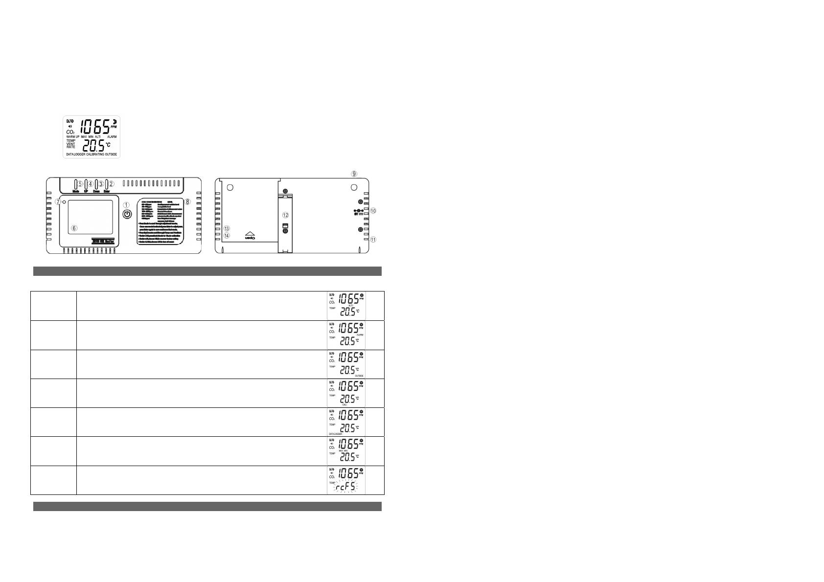
1. Power Button 8. Function Label
2. Enter Button 9.Gas Entry Hole
3. Down Button 10. Power inlet
4. Up Button 11. RJ45 socket
5. Mode Button 12. Housing Stand
6. LCD Display 13. Battery Cover
7. LED Light 14. AA Batteries*4
(Display Features and Modes)
■ WarmUp
It lasts approximately 1min before WARMUP disappears; all the functions will not response during warm up.
■ UserMode
After warm up, the device will stabilize and display the normal CO
2 Reading (Upper Display)- remain visible at all times.
■
Temp and Ventilation Rates (Lower Display)
The Up/Down button(④/③) allows you to scroll through the Temperature and Ventilation Modes.When pressing the Up button,the
lower display will go through the following sequence: TempºC -> TempºF -> Vent Rate lps -> Vent Rate cfm/p
*Note: lps refers to Liter Per Second Per Person; cfm/p refers to Cubic Feet Per Minute Per Person
■ Operation of Mode Adjustment
1.ALTI Mode:
1.1. Press the Mode Button(⑤), ALTI flashs
1.2. Press Mode(⑤) to alter between m(meters) and ft(feet) .
1.3. Press Up/Down(④/③) to adjust the altitude (Step=100m/500ft)
1.4. Press the Enter Button(②), save or leave the ALTI Mode, return to UserMode
2.ALARM Mode
2.1. Adjust the alarm level
2.1.1. Press the Mode button (⑤), until ALARM flashs
2.1.2. Press Enter Button(②), “CO2” icon flashs.
2.1.3. Press Up/Down(④/③) to adjust the alarm level (≧1,000 ppm, interval is ±100ppm; <1,000 ppm, interval is ±50 ppm)
2.1.4. Press the Enter(②), save the setting and return to UserMode.
2.2. Turn ON/OFF the ALARM
2.2.1. Press the Mode button(⑤), until “Speaker Icon” flashs.
2.2.2. Press Enter Button(②)
2.2.3. Press Up/Down(④/③) to turn on/off the ALARM,
2.2.4. Press the Enter(②), save the setting and return to UserMode.
3.OUTSIDE Mode
** Note:Ventilation Rate
Ventilate rate represents how much air is introduced into the indoor space from the outside. Low values indicate low ventilation rates and
potentially poor air quality. High levels indicate excessive ventilation and potential excessive energy usage. To obtain an accurate
measurement, reading should be taken 2~3 hours after occupancy has stabilized in a space or at a peak in daily CO
2 concentrations.
In indoor air quality control, CO
2 value is an indicator of ventilation rate. 400ppm (Parts Per Million) is the default CO2 concentration
outside (according to ASHRAE: American Society of Heating, Refrigeration and Air conditioning Engineers)
3.1. Press the Mode button(⑤) ,until OUTSIDE flashs
3.2. Press Enter(②), show OUTSIDE, CO
2 and PPM flash
Press Up/Down(④/③) to adjust the reading
3.3. Press the Enter(②), save the setting and return to UserMode
After modification, the VENT Rate will change
4. CALI Mode
The CO2 monitor has been calibrated in the factory and should recalibrate every 12 months with a specified concentration of CO2.Sensor drift
usually occurs in linearity. Please follow below steps.
4.1. If battery icon shows low power, please replace new batteries or use AC adapter
4.2. Press the Mode button(⑤), until CALI flashs
4.3. Press Enter(②), CALI shows on display
4.4. Adjust the lower display to ambient CO
2 value by Up/Down (④/③) Button.
4.5. Press Mode button(⑤) more than 10 sec., CALIBRATING flashs.
Calibration will be done after 5 min and LCD will appear “PASS”.If LCD appear “FAIL”, please calibrate once again.
4.6. Press Enter(②), return to UserMode
5. DATA LOGGER Mode
AIRCO2NTROL 3000 has a built-in datalogger , which can provide users the past CO2 and temperature readings within the past 24 hours.
5.1. Press the Mode button(⑤), until DATALOGGER flashs
5.2. Press Enter(②),CO
2 and Temperature show up
Press Up/Down(④/③) to page up/down the reading .
5.3. Press the Enter(②), return to UserMode


