Page is loading ...


Ol-\c-€ Ve€s,e,,.t
AU
lilDililt@
OPERATING
INSTRUGTIONS
AND
CONNECTIONS
SA
SERIES
MIXER
AMPLIFIERS
Audio Telex
Communicolions Ply Lld
SYDNEY
'12G124
Beoconsfield
St
AUBURN
NSW 2144
Pri\ote
Bog 114
ERMINGTON NSW
2115
Phone
(02)
647
1411
Fcx
(02)
648
3698
MEI.BOURNE
4/2630
Howteys Rood
NOTNNG HILI VIC
3168
P,
O. Box 468
MT WAVERIfY VIC
3149
Phone
(03)
562
8566
Fox
(03)
562 8781
BRISBAI{E
42
Commerciol Rood
P,
O, Box
871
FORIruDE
VALLEY
OLD 4M6
Phone
(07)
852 1312
Fox
(07)
252 1237
PERIH
ADEWDE
Unit 7/M{6 Kent
Street
Eleclronic
Concepts
Connington
76
George
St, theborton
P, O, Box 489
61A7
P,
O, Box
7034
HuttSt50Ol
Iel
(09)
356 2761
Tel
(08)
234 9444
Fox
(09)
356 2762 Fox
(08)
234 9441
NEW
ZEAIAND
8 Collins
Sfeet
MORNINGSIDE
AUCKLAND
Phone
(tl9)
86
7032
Fox
(09)
89 4588

OPERATING
INSTRUCTIONS
SA SERIES
AMPLIFIERS
SA SERIES
MIXER
AMPLIFIERS
Congratulations
on
your
purchase
of our
SA series
mixer amplifier.
As
you
are
no
doubt
aware
,
mains
power
must
be disconnected before
removing the
lid
or
making
any
internal
adjustments
or connections
to
the amplifier.
The
SA Series
Mixer
Amplifiers
are two
rack
height
units suitable
for
direct
rack mounting
in
a
standard
482mm
rack
format,
or desV
table mount by
means of the
rubber feet
provided.
They
are equipped
with lour
balanced
microphone
inputs,
one
line
input
and
two auxiliary
inputs
(switched). The
following
informa tion
will
provide
setting up
and connectior(iirformation
for use
in
a conventional
sound
reintorcement
system.
More
detailed
information
and
performance
data
is
available
from
your
dealer
or any
Audio
Telex
Communication's oflice.
SETTING UP
For normal
operation
the
master
gain
control should be set
at
mid
position
and the
various
microphone
,
line
or auxiliary cpntrols adjusted
to their desired
level. See details
under
"
controls"
below.
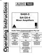
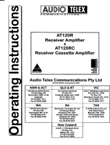
PANEL
CONTROLS
(fig
1
)
7...."
MASTER
"
This
control
adjusts the overallvolume
from the output of the
mixer section
of the
amplifier.
Normal
position
for this control
is
5
,
which will enable
the overall
volume
level from the amplifler
to be
adjustecl up or
down as
required.
1...."
MIC
"
Marked one
to
four,
these controls
will respond to
microphone inputs connected
at the
rear
of
the
amplifier.The
setting
will
depend
upon the sensitivity
of the
microphone,
which is connected.
Generally
a
setting
of
six to seven
is ideal for
most
dynamic
microphones
with an
impedance of
200 ohms,
however the
purpose
of multiple microphone
inputs is to enable
microphones o{
varying levels to be
mixed to
produce
the
desired
performance
level.
2...."
LINE
"
The line
input will respond to
inputs connected
to the appropriate
connections
at the
rear of the
amplilier.Generally,
program
sources
sucfi
as a tape deck,
cd
disc
player,
telephone
line
or
wireless
microphone can be connected
to this
input.
3...."
AUX
"
The
auxiliary
control
is
used
in
conjunction
with the switch
marked
"
AUX1
-
AUX2
"(4).
Auxiliary
inputs such as
tape decks, background
music
players,
radio tuners
or
wireless microphones
are some
of
the
sources
normally
connected
to these
inputs.
The
switch
"
AUX1
-
AUX2
"
should
be
pressed
"
in
"
to connect
auxiliary
input one and
"
out
"
to connect auxiliary
input two.
Note that
it is not
possible
to amplify
both
auxiliary
inputs
simultaneously
,
although they
can be
permanently
connected
,
(
see connection
details
)
.
5...." BAS.S
"
The
bass
control
will
normally
be
operated
in the
zero
position
to
obtain a
flat
overall
responsefor the amplifier.
To
boost the
bass
response ol the amplilier
turn the control
clockwise
towards
five. To cut bass
response turn the cantrol counter
clockwise
towards
five.
6...."
TREBLE
"
The
treble
control
will normally be operated
in the
zero
position
,
which sets
the treble
response
of
the amplifier
for
a flat
performance.
To
boost the
high frequency
perform
ance
of the
amplilier
,
adjust
the control cloclarvise
towards
five. To
cut the
high frequency
response
,
turn
the control
counter
dockwise
towards
five.
9...."
VU METER
"
Marked
in
decibel
graduation
from
+3
to 21
,
the
light
emitting
diodes
will indicate
the
volume
level
at the output
of the amplifier.
For normal operation
the
l.e.d.s
glow green
as they
modulate
with
the output
level of the amplifier.
lf the
lights
cunsistently
indicate red, the amplifier
is
being
over-driven
,
resulting
in
distortion
in the
quality
of the output
signal.
8...."
POWER
"
This switch turns
on or off the
mains
power
to the
amplifier.
An
Le.d.
glows
red to
indicate
the amplifier
is
turned
on.
e-
lT
'n
t
r
-
I I
r(
lt
?(
9l
loroo
I tl
vrcr
Mr'
a,)
-:_
i
o
rlo rj-o
? 3
o
? tr
o
,7
13
:l
to
r(
l0
79 ,\
-/9
i'\
-,e
i'
'"*:t
t";lt
r_l)

OPEBATI NG INSTRUCTIONS
SA
SER]ES
AMPLIFIERS
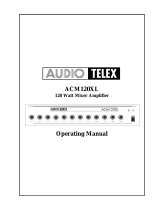
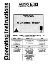
CONNECTIONS
(fig2)
o-o o
#1.
o ol
O O O-'..o/
AUxz AUxl LrNE
-.---O
O
O
Mrc4
aa-i""
7--.,
(.
o)
i
'o
ol
\o,/i\o,/
\-/O
i
I
vO
:
)-
IL
do
1.... Three
pin
IEC
mains
power
inlel24Ol120
vac with
built
in fuse
drawer and spare
fuse.
Ensure the mains
cord
is
disconnected
before
replacing
the
fuse.( Fuse
sizes
are
indicated further
on
in
these
instructions.
)
2....
Terminalstrip
lor
speaker
connections are
from
left to right
as
follows;
term
1.....
B ohms)
term 2.....
I ohms)
term 3..... Common
return
for 70
and 1OOvolt line.
term
4..... 70
volt
output.
term 5.....
100 volt
output.
term 6..... Spare(
ldealfor
connection of tone
generator)
lerm
7.....
Spare(
remote
start or any ancillary control
)
3....24
volts
dc
power
source input, two
post
type terminals
RED
+
BLACK
-
.
4.... DC
low
voltage fuse . Remove with
a screwdriver after disconnecting mains
power.
5.... External aluminium heat
sink.
As
this unit
generates
heat
during continuous
operation
,
care should be
taken to avoid skin
contact
wilh it.
6.... Auxiliary inputs,
connections are twin RCA type
phone
connectors
,
allowing up to two auxiliary sources
to be connected.
7.... Balanced $ansformer output, male XLR
socket. Pin connections... 1.. eafih 2... active 3...
active.
8....
Tape recorder
output
,
twin
RCA
phone
connectors to enable
left
and
right
stereo connection for
monauraloutput.
9... Line
input,
twin RCA
phone
type
connectors.
10... Four XLR female microphone inputs,
accept 200 ohms balanced microphones. Connections
Pin 1...
earth
Pin 2...active Pin
3...active.

OPERATING INSTRUCTIONS
SA SERIES AMPLIFIERS
SPECIAL ACCESSORIES
TONE
GENERATORS
;
Four
types of tone
generators
are avail able
as options . They
are easily
fined
by
first removing
the mains
cord
and then
,
by
means
of screws
on either
side,
remove
the
lid. Attach
the
module
to the
metal
base
of the
amplifier, using the
adhesive tape
provided.
Ptug
the seven
pin
plug
into
the
socket
as shown
on the
diagram
supplied with
the tone module. Replace
the
lid
and
reconnect
the
mains
cord. Note
the module
can be
switched on
off
from
a
remote
connection
by utilising the spare terminals
described in
"CONNECTIONS"
item 2 .
Operation of the tone
generator
will
automatically mute
the
line
and
auxiliary inputs,
however
the microphone inputs
remain
active
to
ensure
paging
is
possible
during
an
emergency.
Tone
Generators
avaitable
;
ATC5227
Continuous
beil
AfC5228
Pre
announce
chime
ATC5229
Evacuatlon tone
ATC5230
Alert
tone
MICROPHONE
LINE TRANSFORMER
SA4012
;
When long microphone
lines
are utilised
,
there
is
atways a
risk
of
inducing
hum
or
noise
,
particularly
when
there
is
electrical
interference
in
the
vicinity
of the cables.
The
SA4012 is
a
"
plug
in
"
balanced
200
ohm
mic
line
transformer with
a
nu-metal
shleld,which will reduce
the
possibility
of induced hum
and
noise.
.lt is fitted
into
the sockets
provided
for
each
micro
phone
input
,
inside
the amplifier.
To
fit
the SA4012
,
disconnect
the mains
power
and
remove
the
lid
,
by means
of the screws at
either
side,remove
the existing
jumper
plug
for
the reqired input.
Plug
the SA4012 into
the appropriate input
socket, located
on the circuit
board
.(see
diagram with
SA4012
)
VOTCE
OPERATED
MUTTNG
MODULE TX3010;
Automatic
muting
of
ail microphone
,
tine
and auxitiary
inputs is
possible
from microphone
input
one
,
which is
a
designated
priority
input.Voice
operation of a
microphone
in
this input witl
cause
the
module
to switch off
all other
inputs. This function is
ideal
for
muting
background
music
or other sources
during
paging.
To fit
the
TX3010
module,
discunect
the mains
power
and
remove
the
lid
of the amplifier
by
means
of the
screws on
either side . Remove
the
jumper
plug
from
the socket adiacent microphone input
one
(
see
MIC/LINE INPUT
CONVERSION MODULE
;
Any microphone
input
on the
5460 and SA120 can be
converted
to
an extra
line
input
by
means
of the
TX3011.
The function is
useful for
accepting
high level
paging
inputs
such
as a telephone
or telecom line.
To
fit
the
TX3011
disconnect
the
mains
and
remove
the
lid. Remove
the existing
jumper
plug
lrom
the
required
mic input
socket located
on the circuit
board.
Plug
the TX3011 into
the socket and
replace
the
rid.
FUSE
SIZES SA
AMPLIF]ERS
MAINS FUSE
RATINGS
DC FUSE RATINGS
SA3O.....1AMP
SB
3AMPS SB
SA6O.....2AMP
SB
sAMPS
SB
SA12O..4AMPS
SB
10 AMPS
SB


/