Page is loading ...

ITEM #0309527
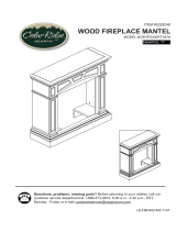
WOOD FIREPLACE MANTEL
Questions, problems, missing parts? Before returning to your retailer, call our
customer service department at 1-866-573-0674, 8:00 a.m - 4:30 p.m., EST,
Monday - Friday or e-mail [email protected].
LS-FB28C-808-0903
MODEL #SSFBD28TCM-6-CC
Español p. 13

2
PRODUCT SPECIFICATIONS
14.88 in
20.43 in
42.05 in
38.31 in

3
PART DESCRIPTION Quantity
A Top 1
B Panel 1
C Left Side Panel 1
D Ride Side Panel 1
E Base 1
F Top Triangle Panel 1
G Backboard 2
H Set Square Support 1
PACKAGE CONTENTS

4
HARDWARE CONTENTS
AA
ST4 Screw
2 ⅜ in.
22
2Wall Anchor
8
ST4 Screw
1 ⅜ in.
ST4 Screw
⅝ in.
22
Mounting
Bracket
Cam Lock
Cam Dowel
WARNINGS AND CAUTIONS
WARNING
• When tightening screws, do not overtighten. This may cause threads to strip. We recommend
using a hand-powered screwdriver rather than a power screwdriver.
• Do not force screws into holes.
CAUTION
• Forcornerinstallations(optional);ifbaseboardsareinstalledwherethereplaceisintended
tobedisplayed,thenthereplacewillnottushagainstthewall.Foraproperusht,you
may need to remove part of the baseboard moulding if necessary.
PREPARATION
Before beginning assembly of product, make sure all parts are present. Compare parts with
package contents list and diagram above. If any part is missing or damaged, do not attempt to
assemble the product. Contact customer service for replacement parts.
Estimated Assembly Time: 60 minutes
Tools Required for Assembly: Philips Screwdriver, Flathead Screwdriver, Drill, and Tape
Measure
BB
CC
DD
Picture
Part Description Quantity (Shown to size)
FF
3
18
GG
EE
2
(not actual size)
Picture
Part Description Quantity (Shown to size)
1Red Key
HH

5
Fig. 2
1. Insert Cam Locks (BB) into left side and
right side of Panel (B). Screw in Cam Dowels
(AA) into Left Side Panel (C) and Right Side
Panel (D) by tightening the Cam Locks (BB) as
shown in Fig.1
Hardware Used
Cam Dowels
Fig. 1
x4
x4
ASSEMBLY INSTRUCTIONS
AA
BB
Cam Locks
2. Insert Cam Locks (BB) into Left Side Panel
(C) and Right Side Panel (D). Screw in Cam
Dowels (AA) into Base (E). Attach Base (E)
into assembled frame (B,C,D) by tightening
the Cam Locks (BB) as shown in Fig. 2.
Cam Dowel
x6
x6
AA
BB
Cam Lock
Hardware Used
Skip to step 5 for Corner Mantel Installation.
D
D

6
Fig. 3
4. Place insert (sold separately) into the mantel as shown in Fig. 4.
Fig. 4
3. Insert Cam Locks (BB) into Left Side Panel
(C), Right Side Panel (D) and Panel (B).
Screw in Cam Dowels (AA) into Top (A). Attach
Top (A) into assembled frame by tightening the
Cam Locks (BB) as shown in Fig. 3.
Hardware Used
Cam Dowel
x6
x6
AA
BB
Cam Lock
D

7
x 3
Fig. 5
Fig. 6
ASSEMBLY INSTRUCTIONS CONTINUED (CORNER MANTEL)
5. Turn the Top (A) over. Using the Mounting
Bracket (GG), connect the Top (A) to the Top
Triangle Panel (F) with ST4 Screw -5/8 in.
(FF) as shown in Fig. 5.
Hardware Used
ST4 Screw - ⅝ in.
x 18
Mounting
Bracket
6. Insert Cam Locks (BB) into Left Side
Panel (C), Right Side Panel (D) and Panel
(B). Screw in Cam Dowels (AA) into Top (A).
Attach assembled top into assembled frame
by tightening the Cam Locks (BB) as shown in
Fig. 6.
Hardware Used
Cam Dowel
x6
x6
AA
BB
Cam Lock
FF
GG
D

8
D
Fig. 7
Fig. 8
Hardware Used
Wall Anchor
x2
7. Attach the left and right Backboard (G) trim
piecestothebackofthereplacewithST4
Screw - 1 ⅜ in. (DD) as shown in Fig. 7.
Hardware Used
DD
ST4 Screw - 1 ⅜ in.
x 8
8. Drill two holes (5/16 in.) in the corner
wherethereplaceistobedisplayed.Drill
thersthole34⅛ in. from the ground up;
and the second hole 36 ⅞ in. from the ground
up as shown in Fig. 8. Put the Wall Anchors
(CC) in the holes by pinching the anchor tabs
together.
CC
Mitered Corner
Joints

9
HH
H
EE
H
Fig. 10
9. Attach the triangular wood block to the holes
drilled in step 8 with ST4 Screw - 2 ⅜ in. (EE) as
shown in Fig. 9. This block is used to support the
Set Square Support (H). For thin walls, insert red
key (HH) into wall anchor and push to “pop” open
anchor wings.
Fig. 9
Hardware Used
EE
ST4 Screw - 2 ⅜ in.
x 2
10.Pushreplaceintocornersothatthe
Top Triangle Panel (F) is resting on top of the
Set Square Support (H) as shown in Fig. 10.
Baseboard
Mitered Corner
Joints
Mantel
Insert
x 1Red Key
HH

10
REPLACEMENT PARTS
NOTE: Use only original replacement parts. This will protect your warranty coverage for parts
replaced under warranty.
PARTS UNDER WARRANTY
Call Customer Service toll free at (1-866-573-0674) for referral information.
When calling Customer Service, have ready:
• Yourname
• Youraddress
• Modelandserialnumberofyourheater
• Howheaterwasmalfunctioning
• Typeofgasused(Propane/LPorNaturalgas/NG)
• Purchasedate
• Usually,wewillaskyoutoreturnthedefectiveparttothefactory
PARTS NOT UNDER WARRANTY
Call Customer Service toll free at (1-866-573-0674) for referral information.
When calling Customer Service have ready:
• Modelnumberofyourheater
• Thereplacementpartnumber

11
REPLACEMENT PARTS LIST
For replacement parts, call our customer service department at
1-866-573-0674,
8:00 a.m - 4:30 p.m., EST, Monday - Friday or e-mail [email protected].
Part. Description Part #
AA Cam Dowel GB/T 6478 - 2001
BB Cam Lock GB/T 6478 - 2001
CC Wall Anchor ML066 - 01
DD ST4 Screw 1 3/8 in. GB/T 951 - 4 x 35
EE ST4 Screw 2 3/8 in. GB/T950 - 4.8 x 60
FF ST4 Screw 5/8 in. GB/T 951 - 4 x 16
GG Mounting Bracket SJ 002
HH Red Key ML067 - 01
AA
BB
CC
DD
EE
FF
GG
HH

12
2-YEARLIMITEDWARRANTY
The manufacturer warrants this product to be free from defects in workmanship and material
present at time of shipment from the factory for two (2) years from the date of purchase. This
warranty applies only to the original purchaser. The manufacturer agrees to correct such
defect at no charge or, at our option, replace the product with a comparable or superior model.
Toobtainwarrantyservice,callourcustomerservicedepartmentat1-866-573-0674.You
may be required to present a copy of your sales receipt as proof of purchase. All costs of
removal and reinstallation are the expressed responsibility of the purchaser. Any damage to
theproductbyaccident,misuse,improperinstallation,orbyafxingaccessoriesnotproduced
by the manufacturer, are the purchaser’s responsibility. The manufacturer assumes no
responsibility whatsoever for installation during the warranty period.
There is no further expressed warranty. The manufacturer disclaims any and all implied
warranties. The manufacturer shall not be liable for incidental, consequential, or special
damages arising at or in connection with product use or performance except as may otherwise
beaccordedbylaw.Thiswarrantygivesyouspeciclegalrights,andyoualsohaveother
rights which vary from state to state. This warranty supersedes all prior warranties.
Printed in China
/


