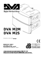
dBTechnologies DVA M2M+DVA M2S Owner's manual
- Category
- Car audio amplifiers
- Type
- Owner's manual

DESIGNED & DEVELOPED
IN ITALY
MANUALE D’USO - Sezione 1
USER MANUAL - Section 1
BEDIENUNGSANLEITUNG - Abschnitt 1
CARACTERISTIQUES TECHNIQUES - Section 1
Le avvertenze nel presente manuale devono essere osservate congiuntamente al “MANUALE D’USO - Sezione2”.
The warnings in this manual must be observed together with the "USER MANUAL - Section 2".
Die Warnungen in diesem Handbuch müssen in Verbindung mit der "BEDIENUNGSANLEITUNG - Abschnitt 2" beobachtet werden.
Les avertissements dans ce manuel doivent être respectées en collaboration avec le "CARATTERISTIQUES TECHNIQUES - Section 2".
DVA M2M
DVA M2S
Page is loading ...
Page is loading ...
Page is loading ...
Page is loading ...
Page is loading ...
Page is loading ...

DVA MINI Digital Array System
7
ENGLISH
DESCRIPTION
The speakers DVA M2M and DVA M2S are part of the modular system called DVA MINI.
The system can be used in ground stack configuration or suspended in line-array configuration.
The modules use a fast, innovative mechanical fastening method.
This series is ideal for installations in
theatres, places of worship, convention centres, concerts and
live music performances which require medium-high sound pressures and limited weight and
footprint.
DVA M2M is equipped with two class D amplifiers series DIGIPRO
®
G3, able to drive also the
speaker DVA M2S thanks to a simple, easy wiring.
The amplifier module is capable of delivering 400W RMS (total), 200W RMS for the bass section
and 200W (RMS) for the treble section.
The high efficiency of the modules DIGIPRO
®
G3 allows to obtain high output power, with reduced
weight and footprint. Thanks to its low power dissipation, the cooling of the amplifier module takes
place in a static manner, avoiding the use of fans.
The digital pre-amplifier with Digital Signal Processor (DSP) manages the acoustic components,
the frequency response, the limiter and the speaker alerts.
The SMPS (Switched-Mode Power Supply) Power Supply Unit (PSU) thanks to its self-range
technology ensures operation at supply voltages from 100V~ to 120V~ and from 220V~ to 240V~.
Both speakers are provided with the same acoustic components.
The bass section is composed of two 6.5" neodymium woofers
(voice coil 1.5”). The double phase plug in front of each individual
cone avoids horizontal phase overlapping increasing efficiency and
directivity. The double phase plug present in front of each individual
cone brings nearer the point of release of the woofer acoustic
avoiding the overlap of the horizontal phase.
The design of the phase plugs allows the proper matching with the
speakers of the series DVA Mini.
The treble section consists of two 1” neodymium compression
drivers (voice coil 1”) mounted vertically and spaced to optimize
vertical coverage.
The horn has been specially designed for the proper matching of the
speakers of the series DVA Mini.
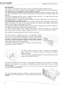
DVA M2M and DVA M2S are made of polypropylene with two rear side handles to facilitate
transport and installation. The speakers are equipped with steel brackets and an easy, simple
locking system.
The rear bracket is graduated (0°-1.5°-3°-4.5°-6°-8°-10°-12.5°-15°) to allow fastening various
speakers with the desired angle.
The accurate design enables to achieve a constant and precise
coverage of 90° horizontally and 15° in the vertical direction for each
speaker.

8
ENGLISH
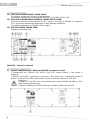
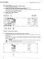
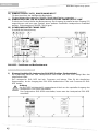
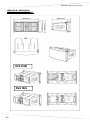
DVA M2M – Functions and controls
"Balanced Audio" section
2) " INPUT” INPUT CONNECTOR
Audio balanced input at line level. It is able to accept “XLR” sockets.
3) "LINK” OUTPUT CONNECTOR
The “XLR” connector connected in parallel with input (1) can be used to send the input audio
signal to another amplified speaker.
"Status" section
4) “LIMITER” INDICATOR LIGHT
This indicator comes on red to indicate that the internal limiter circuit has tripped.
This prevents amplifier distortion and protects the speakers against overloads.
Always avoid operating conditions where the system works for long periods of time
with LED flashes or it is always ON
5) “SIGNAL” INDICATOR LIGHT
This indicator comes on green to indicate the presence of an input signal to a level higher
than -20dBu.
6) “MUTE/PROT” INDICATOR LIGHT
This yellow indicator indicates amplifier status. In normal operating conditions, the LED is off;
if it flashes or is always on, refer to the diagnostics table to check amplifier status.
7) “READY” INDICATOR LIGHT
This indicator comes on green to indicate that the main power voltage is correct. In normal
operating conditions, the LED is on; if it flashes or is off, refer to the diagnostics table.
"Audio Input control " section
8) “INPUT SENS” INPUT SENSITIVITY CONTROL
This control regulates the sensitivity of the signal amplifier input and of the connected
DVA M2S passive speaker.
This control does not affect the “LINK” (2) output level
"DSP configuration" section
9) “DSP Preset” 10-position ROTARY SWITCH
This 10-position rotary switch makes it possible to select the nine preset equalization curves
(selector 0-8)
Position 9 ("user") is reserved for advanced operations such as firmware update. Therefore in
this position, the speaker is not operating and the amplifier is set to mute.
"Service" section
10) “Service Data USB” Connector
Via this USB connector, it is possible to update the firmware of the DVA M2M amplifier
module using the computer and a dedicated program.
"Slave Audio Output" section
11) Amplified output for the speaker DVA M2S (4-pole connector)
The connection between the speakers DVA M2M and DVA M2S is realized by means of the
supplied cable.
Attention
Connect the connector only and exclusively the speaker DVA M2S
Turn off the speaker DVA M2M before connecting the speaker DVA M2S.

DVA MINI Digital Array System
9
ENGLISH
Power supply section
12) "AUTO-RANGE” MAINS INPUT" POWER SOCKET
For connecting the power cable.
The connector used for mains connection is a POWER CON® (blue)
13) “MAINS OUTPUT LINK” RELAUNCH POWER SOCKET
For re-launching the mains power. The output is connected in parallel with input (11) and can
be used to power another amplified speaker.
The connector uses a POWER CON® (grey)
14) "MAINS FUSE" FUSE CARRIER
Mains fuse housing.
DVA M2S – Functions and controls
"Slave Audio Input" section
1) Amplified input for the speaker DVA M2S (5-pole connector)
The connection between the speakers DVA M2M and DVA M2S is realized by means of the
supplied cable.
The speaker DVA M2S is not equipped with crossover and internal filters for acoustic
components, as the output of the DVA M2M provides for filters and electronic crossovers
dedicated to the DVA M2S.
Attention
Connect to the DVA M2S only and exclusively the dedicated output of the speaker
DVA M2M using the specific cable.
Turn off the speaker DVA M2M before connecting the speaker DVA M2S

10
ENGLISH
CHARACTERISTICS AND PROTECTION
Indications of operation model, malfunction, and safeties
The light indicators (LEDs) "READY", "MUTE/PROT", "SIGNAL" and "LIMIT" are also used to
indicate different modes of operation and different types of faults, by flashing sequences as
reported in the diagnostics table below.
The three types of failure are:
- WARNING: a non-severe error or auto-reset malfunction is detected and the performance of
the speaker is not limited
- LIMITATION: an error is detected and diffuser performance is limited. The sound level is
reduced or one or more amplifiers are disabled. This state partially influences the correct
functioning of the diffuser. If the problem persists the next time the module is turned on,
contact the support center for assistance.
- FAILURE: a severe malfunction is detected. The speaker switches to “mute”.
If the case of a malfunction, before contacting the support center, try to turn the module off and on
to check if the problem still exists.
Cooling
The cooling of the amplifier on the speaker DVA M2M is realized by convection on internal heat
sinks without the aid of fans.
Thermal protection is ensured by an internal circuit which controls the temperature of the amplifier
and protects it from overheating by limiting the overall volume.
This intervention is marked by the flashing of a yellow indicator light "MUTE/PROT".
The correct volume and all the functions will be automatically restarted after normal operating
temperatures have been restored.
Protection
When the yellow “MUTE/PROT” LED turns on, it means that a malfunction has been detected on
the speaker, thus setting this to the mute position.
Perform the checks listed below:
- Check if the speaker is properly connected to the power supply.
- Make sure that the power supply is of correct voltage.
- Check that the amplifier is not overheated.
- Disconnect the speaker from the mains power supply, wait for a few minutes and connect
it again.
If after these tests the LED is still on, please contact an authorized service center.
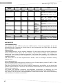
DIAGNOSTICS TABLE
STATE OR
CONDITION OF THE
MODULE
LED
“READY”
LED
“MUTE/PROT”
LED
“SIGNAL”
LED
“LIMITER”
FUNCTIONS OR DESCRIPTION OF THE
MODULE
Normal operation
Power ON
OFF
ON for 5 sec.
OFF
OFF
Audio MUTED
Initialization of the amplifier module
Normal use
ON
OFF
Normal
operation
Normal
operation
Audio ACTIVE
Module initialization complete and correct
Partial fault
ON
Cycling
flashing (quick
flashes)
Normal
operation
Normal
operation
Audio ACTIVE
The module has detected a partial anomaly
and remains active with limited functions
Total fault
OFF
ON
OFF
Cycling
flashing (quick
flashes)
Audio MUTED
The module has detected a serious anomaly
and is in protected mode

DVA MINI Digital Array System
11
ENGLISH
STATE OR
CONDITION OF THE
MODULE
LED
“READY”
LED
“MUTE/PROT”
LED
“SIGNAL”
LED
“LIMITER”
FUNCTIONS OR DESCRIPTION OF THE
MODULE
Amplifier temperature management
Amplifier temperature
(thermal threshold)
Normal
operation
Cycling
flashing
Normal
operation
Normal
operation
Audio ACTIVE
The amplifier module reduces the volume, in
steps of 0.1 dBm up to a maximum of 6dBm,
as the temperature rises above the safety
threshold.
Generic errors
No power supply (Vac)
detected
OFF
ON
OFF
OFF
A momentary lack of supply voltage is
detected during normal operation
Current overload
OFF
ON
OFF
ON
A current overload is detected during normal
operation.
Communication error
with the DSP
OFF
ON
OFF
Cyclic flashing
(1slow flashes)
A communication error between the
preamplifier and the processor of the audio
signal has been detected.
Incorrect configuration
OFF
ON
OFF
Cyclic flashing
(2slow flashes)
The settings of the amplifier module do not
match the hardware configuration of the
module.
Incorrect firmware
OFF
ON
OFF
Cyclic
flashing
(3slow flashes)
The DSP firmware does not match the version
of the pre-amplifier
USB Mode
Bootloader function
ON
OFF
OFF
They flash alternately
The bootloader function in the pre
-
amplifier is
active
Telemetry ON
They flash alternately
OFF
OFF
The amplifier module is connected to the USB
port for downloading the telemetry
CONNECTIONS
USB Data Link
The speaker DVA M2M is equipped with a USB "Service" connector, useful for the firmware update
of the module or to download speaker operation data.
Connecting to the mains supply
Each active speaker features its own power cable. Connection is done by a Neutrik POWER
CON® (Blue) model which permits easy and fast connection to the speaker as well as being an
excellent locking system.
The POWER CON connector acts as the disconnecting device for the power supply and must be
easily accessible after installation and during use of the speaker
The active speaker must be connected to a power supply able to deliver the maximum required
power.
Main power supply linking
On the rear of the speaker, a Neutrik POWER CON® connector (Grey) offers linking the mains
power supply.
This socket links the power supply to another speaker, thereby reducing the direct connections to
the mains. Maximum amplifier input power is shown on the amplifier panel.
The maximum number of speakers connected to the LINK OUT connector varies depending on the
voltage of power supply used and the type of connected speaker to this socket. Do not exceed in
any case the maximum current / power specified in the data on the panel. This failure can cause
overheating and damage to the products.

12
ENGLISH
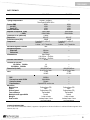
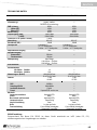
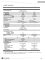
TECHNICAL SPECIFICATION
DVA M2M
DVA M2S
System
Active 2
-
Amps
Passive
Type of amplifier
Digital
–
Class D
DIGIPRO G3
TM
technology
---
RMS power
High (HF)
Low (LF)
200W
100W
100W
200W
100W
100W
Musical power
400W
400W
Frequency response (
-
6dB)
(-10dB)
78
Hz
-
19KHz
68Hz-20KHz
78
Hz
-
19KHz
68Hz-20KHz
Crossover LF
-
HF (low
-
high)
1,8
KHz
Cover range
90°x15°
90°x15°
Sound pressure (SPL)
126dB
126dB
Component parts
2 woofer 6,5”
–
VC 1,5” Neodymium
2 driver – VC 1” Neodymium
2 woofer 6,5”
–
VC 1,5” Neodymium
2 driver – VC 1” Neodymium
Input sensitivity nominal
0dB
---
Input impendence
Balanced
Unbalanced
20Kohm
10Kohm
---
Power supply
Auto
-
Range
100-120Vac 50-60Hz
220-240Vac 50-60Hz
----
Inrush current
20.6A
---
Current consumption
100-120Vac 50-60Hz
220-240Vac 50-60Hz
1A
0,5A
---
---
Dimensions (LxHxP)
460x190x345mm
18.1x7.5x13.6 inch.
460x190x345mm
18.1x7.5x13.6 inch.
Weight
7.7Kg
16.8lbs
7.1Kg
15.7lbs
DSP processor
DSP
Audio conversion AD/DA
Volume control
Equalization
28/56bit
24bit/48KHz
Digital
9 preset EQ/1 service use
---
---
---
--
Mechanical parts
Box material
Colour
Box internal reinforcement
Housing shape
Stirrup material
Handle
Frontal grille
Polypropylene (PP)
Black
Polypropylene (PP)
Trapezoidal
Steel
1 x each side
Performed sheet 1.2mm
with internal foam
Polypropylene (PP)
Black
Polypropylene (PP)
Trapezoidal
Stell
1 x each side
Performed sheet 1.2mm
with internal foam
EMI CLASSIFICATION
According to the standards EN 55103 this equipment is designed and suitable to operate in E3 (or
lower E2, E1) Electromagnetic environments.
Page is loading ...
Page is loading ...
Page is loading ...
Page is loading ...
Page is loading ...
Page is loading ...
Page is loading ...
Page is loading ...
Page is loading ...
Page is loading ...
Page is loading ...
Page is loading ...

DVA MINI Digital Array System
25
DVA USB Manager
Il firmware del modulo amplificatore può essere aggiornato tramite la porta USB.
Per rendere possibile e facile questo aggiornamento è stato sviluppato un programma dedicato.
Si raccomanda di scaricare il software gratuito DVA USB Manager direttamente dal sito
dB Technologies (www.dbtechnologies.com) nella sezione dedicata “Software &
Controller”
DVA Composer - Simulazione acustica di sistemi serie DVA
DVA Composer è un software di puntamento e simulazione acustica per tutti i modelli Line Array
della serie DVA e relativi Subwoofers.
Tale software permette di gestire un sistema stereo composto da line array e subwoofer,
simulandone separatamente la risposta acustica di entrambi
Vengono inoltre fornite all'utente una serie di informazioni quali: allineamento in fase tra i sistemi
sospesi e i relativi subwoofer a terra; vengono suggeriti gli angoli ottimali tra i moduli che
compongono i line array e i relativi preset di equalizzazione da assegnare, al fine di consentire
anche ad utenti non esperti di ottimizzare le performance del sistema.
Si raccomanda di scaricare gratuitamente il software DVA_Composer direttamente dal
sito dB Technologies (www.dbtechnologies.com) nella sezione dedicata «Software &
Controller»
DVA USB Manager
The firmware of the amplifier module can be updated via the USB port.
To make this update possible and simple, a dedicated program has been developed.
It is recommended to download DVA USB Manager free software directly from dB
Technologies (www.dbtechnologies.com) in the special section «Software & Controller»
DVA Composer Acoustical Simulation and aiming for DVA Systems
DVA Composer is a software for aiming and simulating acoustical response of all line arrays and
Subwoofers from DVA Series.
The software allows you to set up a stereo system composed by tops and subs, and simulates
separately the acoustical response of both
DVA Composer also gives to the user all the information about phase alignment between flown
systems and ground stacked subwoofers, as well as it suggests an optimized aiming of the line
arrays modules and their suggested EQ presets, in order to guarantee maximum performances
even for non-expert customers.
It is recommended to download DVA_Composer free software directly from dB
Technologies (www.dbtechnologies.com) in the special section «Software & Controller»
ITALIANO
ENGLISH
Page is loading ...
Page is loading ...

28
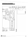
SCHEMA A BLOCCHI - BLOCK DIAGRAM
BLOCKSCHALTBILD - SCHEMAS FONCTIONNELS

DVA MINI Digital Array System
29
DVA MINI – Quick configuration

30
INSTALLAZIONE - INSTALLATION
INSTALLATIONEN - INSTALLATIONS
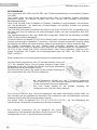
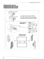
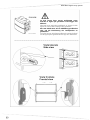
INDICAZIONE POSIZIONE DEL PERNO NELLA STAFFA POSTERIORE
INDICATION OF THE POSITION OF THE PIN IN THE REAR BRACKET
ANGABE DER POSITION DES ZAPFENS IM HINTEREN BÜGEL
INDICATION POSITION DE LA GOUPILLE SUR L'ETRIER POSTERIEUR
Posizione della staffa a riposo (chiusa all’interno delle staffe)
Position of the bracket in rest position (closed inside the brackets)
Ruhestellung des Bügels (in den Bügeln geschlossen)
Position de l'étrier au repos (fermé à l'intérieur des étriers)
Posizione della staffa in blocco con angolazione desiderata
Position of the bracket in block with desired angle
Blockierungsposition des Bügels mit gewünschtem Winkel
Position de l'étrier bloqué avec disposition en angle désirée
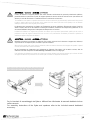
ATTENZIONE
Se il perno NON è inserito all’interno del blocco, il
diffusore NON è bloccato
ATTENTION: If the pin is NOT inserted within the
block, the speaker is NOT locked
ACHTUNG : Wenn der Zapfen NICHT im Block
eingesetzt ist, ist der Lautsprecher NICHT blockiert
ATTENTION : Si la goupille N'est PAS insérée à
l'intérieur du blocage, le diffuseur N'est PAS bloqué
Verificare sempre il corretto inserimento del perno di blocco per
evitare movimenti pericolosi nel caso di fuoriuscita del perno di
stazionamento.
Always check the correct insertion of the lock pin to avoid
dangerous movements in case of release of the parking pin
Immer den korrekten Sitz des Blockierungszapfens prüfen, um
gefährliche Bewegungen beim Heraustreten des Haltezapfens
zu vermeiden.
Toujours vérifier la correcte insertion de la goupille de blocage
pour éviter des mouvements dangereux en cas de sortie de la
goupille de retenue

DVA MINI Digital Array System
31
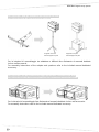
UNIONE DVA M2M – DVA M2S
COMBINATION DVA M2M – DVA M2S
KOMBINATION DVA M2M - DVA M2S
COMBINAISON
DVA
M2M
-
DVA
M2S
La posizione dei due diffusori è indicativa
The position of the two speakers is indicative
Die Position der beiden Lautsprecher Indikativ
La position des deux haut-parleurs est indicatif
Page is loading ...

DVA MINI Digital Array System
33
La leva Rossa deve essere posizionata come
indicato in figura per garantire il bloccaggio dei
diffusori
The Red lever must be positioned as shown in the
figure to ensure the locking of the speakers
Der rote Hebel muss wie in Abbildung positioniert
sein, um die Blockierung der Lautsprecher zu
garantieren
Le levier Rouge doit être positionné comme indiqué
sur la figure pour garantir le blocage des diffuseurs
Page is loading ...

DVA MINI Digital Array System
35
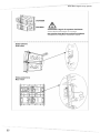
Selezionare l’angolo di copertura desiderato
Select the desired angle of coverage
Den gewünschten Deckungswinkel auswählen
Sélectionner l'angle de couverture désiré

36
Procedere con la medesima sequenza nel caso di più diffusori in configurazione appesa e in
appoggio
Proceed with the same sequence in the case of multiple speakers in suspended and stack
configuration
In derselben Reihenfolge arbeiten, wenn mehrere Lautsprecher aufgehängt werden und stack
Répéter la même séquence en cas de plusieurs diffuseurs en configuration suspendue en stack
Bloccare la staffa con il pin in uno dei due
fori indicati in figura
Lock the bracket with the pin in one of the
two holes indicated in the figure
Den Bügel mit dem Zapfen in einem der
beiden Öffnungen, die in Abbildung gezeigt
werden, blockieren
Bloquer l'étrier avec la goupille dans l'un des
deux orifices indiqués sur la figure
Page is loading ...

38
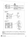
AVVERTENZA – WARNING – ACHTUNG - ATTENTION
L'utilizzo del diffusore su supporto piantana deve essere effettuato esclusivamente da personale professionale qualificato,
prestando attenzione a posizionare un piede del supporto piantana in direzione del lato di uscita del suono (lato anteriore del
diffusore) in modo da massimizzare la stabilità del sistema in relazione al suo baricentro.
The installation of the speaker on speaker stand must be carried out exclusively by professionally qualified staff, being careful
to place a speaker stand foot in the direction of the output side of the sound (front side of the speaker) so as to maximize
stability in relation to the centre of gravity of the speaker
Die Benutzung des Lautsprechers mit Ständer und Topplatte darf nur durch qualifiziertes Fachpersonal erfolgen. Hierbei ist
darauf zu achten, dass ein Fuß des Ständers in Richtung der Schallseite (Vorderseite des Lautsprechers) positioniert ist, um
die höchste Stabilität in Bezug auf den Schwerpunkt des Lautsprechers zu erreichen
L'utilisation du diffuseur sur support avec pied doit être effectué par un personnel professionnel qualifié qui doit veiller à
positionner un pied de support en direction du coté où sort le son (côté antérieur du diffuseur) de manière à optimiser la
stabilité par rapport au barycentre du diffuseur
AVVERTENZA – WARNING – ACHTUNG - ATTENTION
Nell'utilizzo dei diffusori con supporto per subwoofer (Pole mount), assicurarsi che il subwoofer di supporto del/i diffusore/i
sia posizionato su una superficie piana, orizzontale e priva di inclinazioni.
When using the speaker with a pole mount for subwoofer, make sure that the subwoofer which supports the speaker is placed
on a flat, horizontal surface without inclinations.
Bei der Verwendung des Lautsprechers mit Hochständer für Subwoofer (Pole Mount ) fall ist darauf zu achten, dass der
Subwoofer unter dem Lautsprecher auf einer Wohnung, horizontalen und frei von Neigungen.
Pour l'utilisation du diffuseur avec support en colonne pour caisson de basse (pole mount) s'assurer que le caisson de basse
de support du diffuseur soit positionné sur une surface plat, horizontale en dépourvue d'inclinaisons.
ACCESSORIO DRK-M5 (flybar per DVA MINI)
ACCESSORY DRK-M5 (flybar for DVA MINI)
Per le istruzioni di assemblaggio tra flybar e diffusori fare riferimento al manuale dedicato incluso
nell’accessorio.
For assembly instructions of the flybar and speakers refer to the included manual dedicated
accessory.

DVA MINI Digital Array System
39
ACCESSORIO DSA-M2 (adattatore per supporto su asta)
ACCESSORY DSA-M2 (stand supporto adaptor)
Supporto con asta Supporto con palo
Stand support on pole Stand support on pole
Per le istruzioni di assemblaggio tra adattatore e diffusori fare riferimento al manuale dedicato
incluso nell’accessorio.
For assembly instructions of the adapter and speakers refer to the included manual dedicated
accessory.
ACCESSORIO RC-M2 (Protezione pioggia per modulo connettori DVA M2M)
ACCESSORY RC-M2 (Rain cover protection for connectors module DVA M2M)
Per le istruzioni di assemblaggio fare riferimento al manuale dedicato incluso nell’accessorio.
For assembly instructions refer to the included manual dedicated accessory.
Page is loading ...

DVA MINI Digital Array System
41
Page is loading ...
Page is loading ...
-
 1
1
-
 2
2
-
 3
3
-
 4
4
-
 5
5
-
 6
6
-
 7
7
-
 8
8
-
 9
9
-
 10
10
-
 11
11
-
 12
12
-
 13
13
-
 14
14
-
 15
15
-
 16
16
-
 17
17
-
 18
18
-
 19
19
-
 20
20
-
 21
21
-
 22
22
-
 23
23
-
 24
24
-
 25
25
-
 26
26
-
 27
27
-
 28
28
-
 29
29
-
 30
30
-
 31
31
-
 32
32
-
 33
33
-
 34
34
-
 35
35
-
 36
36
-
 37
37
-
 38
38
-
 39
39
-
 40
40
-
 41
41
-
 42
42
-
 43
43
-
 44
44


dBTechnologies DVA M2M+DVA M2S Owner's manual
- Category
- Car audio amplifiers
- Type
- Owner's manual
Ask a question and I''ll find the answer in the document
Finding information in a document is now easier with AI
in other languages
Related papers
-
dBTechnologies DVA MS12 User manual
-
 A.E.B. T12 User manual
-
-
-
 AEB DVA S1521N User manual
-
 AEB DVA T8 User manual
-
-
-
-
A.E.B. DVA S08DP User manual


Other documents
-
 T'nB CB01 Datasheet
-
dB Technologies DVA K5 Quick start guide
-
dB Technologies SUB 618 Quick start guide
-
dB Technologies DVA KS20 Quick start guide
-
AKG AMM 10 Owner's manual
-
Comelit 49DPQO06 Technical Manual
-
RCF ACUSTICA H series User manual
-
Jensen SMPS-560 User guide
-
Focal Performance Expert DSA 500 RT User manual
-
