Sony HTP-36SS User manual

Category
Audio tuners
Type
User manual
model name1[HTP-36SS]
[2-681-273-12 (1)]
l
ename[C:\Documents and
S
ettings\pc13\Desktop\JC060000_2681273121HTP36SS_GB\2681273121\GB01COV_HTP-36SS-CEL.fm]
masterpage:Right
©2006 Sony Corporation
2-681-273-12 (1)
DVD Home
Theatre System
Operating Instructions
HTP-36SS
GB01COV_HTP-36SS-CEL.book Page 1 Friday, March 17, 2006 2:27 PM
2
GB
C:\Documents and
Settings\pc13\Desktop\JC060000_2681273121HTP36SS_GB\2681273121\GB02REG_HTP-
36SS-CEL.fm2-681-273-12 (1)
masterpage: Left
model name1[HTP-36SS]
2-681-273-12 (1)
To reduce the risk of fire or electric
shock, do not expose this apparatus to
rain or moisture.
To prevent fire, do not cover the ventilation of the
apparatus with newspapers, table-cloths, curtains,
etc. And don’t place lighted candles on the
apparatus.
To prevent fire or shock hazard, do not place objects
filled with liquids, such as vases, on the apparatus.
Don’t throw away batteries with
general house waste; dispose of
them correctly as chemical waste.
For customers in Europe
Disposal of Old Electrical & Electronic
Equipment (Applicable in the European
Union and other European countries
with separate collection systems)
About This Manual
The instructions in this manual are for model
HTP-36SS. In this manual, models of area code
CEL is used for illustration purposes unless stated
otherwise. Any difference in operation is clearly
indicated in the text, for example, “Models of area
code CEL only”.
The HTP-36SS consists of:
Receiver STR-KS1000P
DVD player DVP-NS36
Speaker system
a)
Front speakers SS-MSP1000
Center speaker SS-CNP1000
Surround speakers SS-SRP1000
Sub woofer SS-WP1000
a)
Be sure to use only the supplied speakers.
The instructions in this manual describe the
controls on the supplied remote. You can also use
the controls on the receiver if they have the same
or similar names as those on the remote. For
details on the use of your DVD player, refer to the
operating instructions supplied with the DVD
player.
This receiver incorporates Dolby* Digital and Pro
Logic Surround and the DTS** Digital Surround
System.
* Manufactured under license from Dolby
Laboratories.
“Dolby”, “Pro Logic” and the double-D symbol
are trademarks of Dolby Laboratories.
**“DTS” and “DTS Digital Surround” are
registered trademarks of Digital Theater
Systems, Inc.
WARNING
Do not install the appliance in a confined space,
such as a bookcase or built-in cabinet.
This symbol on the product or on its
packaging indicates that this product
shall not be treated as household waste.
Instead it shall be handed over to the
applicable collection point for the
recycling of electrical and electronic
equipment. By ensuring this product is
disposed of correctly, you will help
prevent potential negative
consequences for the environment and
human health, which could otherwise
be caused by inappropriate waste
handling of this product. The recycling
of materials will help to conserve
natural resources. For more detailed
information about recycling of this
product, please contact your local
Civic Office, your household waste
disposal service or the shop where you
purchased the product.
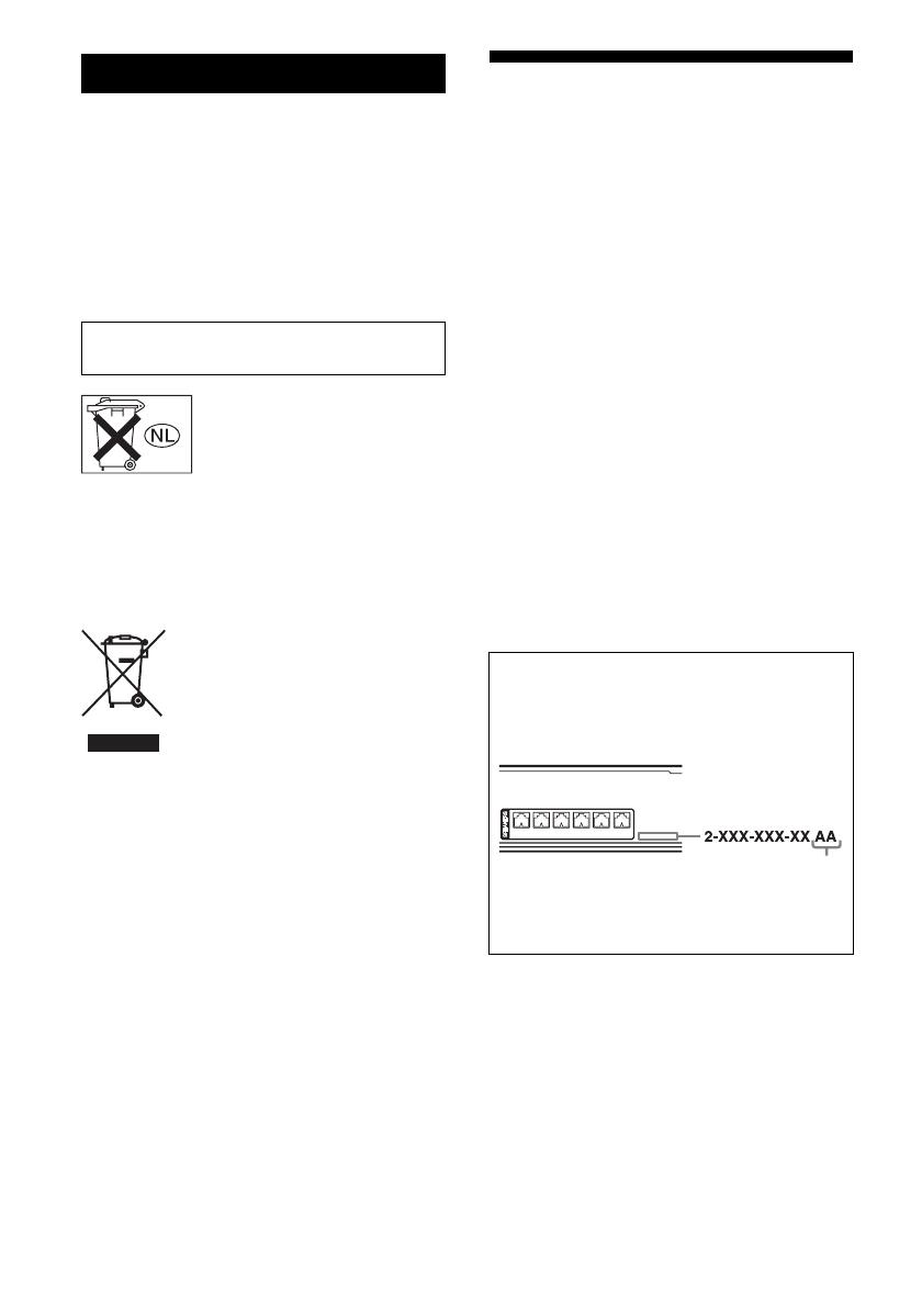
About area codes
The area code of the receiver you purchased is
shown on the lower portion of the rear panel (see
the illustration below).
Any differences in operation, according to the area
code, are clearly indicated in the text, for example,
“Models of area code AA only”.
FRONT R
– +
FRONT L
– + – + – + – + – +
SUR R SUR L CENTER
SUBWOOFER
Area code
GB01COV_HTP-36SS-CEL.book Page 2 Friday, March 17, 2006 2:27 PM
3
GB
C:\Documents and
Settings\pc13\Desktop\JC060000_2681273121HTP36SS_GB\2681273121\GB01COV_HTP-
36SS-CELTOC.fm
masterpage: Right
model name1[HTP-36SS]
2-681-273-12 (1)
Table of Contents
Getting Started
Description and location of parts .................. 4
1: Installing speakers................................... 11
2: Connecting speakers ............................... 13
3: Connecting the audio/video
components ............................................ 15
4: Connecting the antennas ......................... 18
5: Preparing the receiver and the remote..... 19
6: Calibrating the appropriate settings
automatically
(AUTO CALIBRATION) ...................... 20
7: Adjusting the speaker levels and
balance (TEST TONE)........................... 23
Playback
Selecting a component ................................ 24
Listening/Watching a component................ 26
Amplifier Operations
Navigating through menus .......................... 28
Adjusting the level (LEVEL menu) ............ 31
Adjusting the tone (TONE menu)............... 32
Settings for the surround sound
(SUR menu) ........................................... 32
Settings for the tuner (TUNER menu) ........ 33
Settings for the audio (AUDIO menu) ........ 33
Settings for the system (SYSTEM menu)... 34
Calibrating the appropriate settings
automatically (A. CAL menu) ............... 36
Enjoying Surround Sound
Enjoying Dolby Digital and DTS Surround
sound (AUTO FORMAT DIRECT) .......36
Selecting a pre-programmed sound field.....38
Using only the front speakers and sub
woofer (2CH STEREO) .........................40
Resetting sound fields to the initial
settings....................................................41
Tuner Operations
Listening to FM/AM radio ..........................41
Storing FM stations automatically
(AUTOBETICAL)..................................43
Presetting radio stations...............................44
Using the Radio Data System (RDS) ..........45
Other Operations
Using the Sleep Timer .................................47
Using the Remote
Changing button assignments......................47
Additional Information
Glossary.......................................................48
Precautions ..................................................49
Troubleshooting...........................................51
Specifications ..............................................53
Index ............................................................55
GB01COV_HTP-36SS-CEL.book Page 3 Friday, March 17, 2006 2:27 PM
4
GB
C:\Documents and
Settings\pc13\Desktop\JC060000_2681273121HTP36SS_GB\2681273121\GB03CON_HTP-
36SS-CEL.fm
masterpage: Left
model name1[HTP-36SS]
2-681-273-12 (1)
Description and location of parts
Front panel
Getting Started
Receiver
VIDEO 1 VIDEO 2 DVD
SA-CD/CD
TUNER
PRESET TUNING SOUND FIELD MUTING
AUTO CAL MIC
MASTER VOLUME
1 52 4 63
q
;
9 8 7
INPUT SELECTOR
?/1
Name Function
A ?/1 Press to turn the receiver
on or off (page 19, 26, 27,
41, 43).
B Display The current status of the
selected component or a
list of selectable items
appears here (page 5).
C Input lamps The lamp of the chosen
input source lights up
(page 24).
D Remote sensor Receives signals from
remote commander.
E INPUT
SELECTOR
Press to select the input
source to playback (page
24, 26, 27, 42, 43, 44, 45,
51).
F MUTING Press to mute the sound
(page 25).
Name Function
G MASTER
VOLUME
Turn to adjust the volume
level of all speakers at the
same time (page 24, 25,
26, 27).
H AUTO CAL MIC
jack
Connects to the supplied
ECM-AC2 optimizer
microphone for the Auto
Calibration function (page
20).
I SOUND FIELD
+/–
Press to select a sound
field (page 36, 38, 40, 41).
J PRESET TUNING
+/–
Press to select a preset
station (page 45).
GB01COV_HTP-36SS-CEL.book Page 4 Friday, March 17, 2006 2:27 PM
5
GB
C:\Documents and
Settings\pc13\Desktop\JC060000_2681273121HTP36SS_GB\2681273121\GB03CON_HTP-
36SS-CEL.fm
masterpage: Right
Getting Started
model name1[HTP-36SS]
2-681-273-12 (1)
About the indicators on the display
L
CR
SL SR
SW
D.RANGE
RDS
ST MONO
MEMORY
S
SLEEP
DIGITAL
DTS
PL
LFE
OPT
COAX
21 3 4 5 6
789q
;
q
a
q
s
q
d
Name Function
A Lights up when the disc being
played back contains an LFE
(Low Frequency Effect) channel
and the LFE channel signal is
actually being reproduced.
B SLEEP Lights up when the sleep timer is
activated (page 47).
C Playback
channel
indicators
L
R
C
SL
SR
S
The letters (L, C, R, etc.) indicate
the channels being played back.
The boxes around the letters vary
to show how the receiver
downmixes the source sound.
Front Left
Front Right
Center (monaural)
Surround Left
Surround Right
Surround (monaural or the
surround components obtained
by Pro Logic processing)
Example:
Recording format (Front/
Surround): 3/2.1
Sound Field: A.F.D. AUTO
D ;DIGITAL Lights up when Dolby Digital
signals are input.
Note
When playing a Dolby Digital
format disc, be sure that you have
made digital connections and the
audio input mode for VIDEO 2
input or SA-CD/CD input is not
set to “V2 ANLG” or “CD
ANLG” (page 34).
LFE
L
CR
SL SR
SW
Name Function
E Preset
station
indicators
Lights up when using the
receiver to tune in radio stations
you have preset. For details on
presetting radio stations, see
page 44.
F D.RANGE Lights up when dynamic range
compression is activated (page
29).
G Tuner
indicators
Lights up when using the
receiver to tune in radio stations
(page 41), etc.
H MEMORY Lights up when a memory
function, such as Preset Memory
(page 44), etc., is activated.
I COAX Lights up when the DVD input is
selected.
J OPT Lights up when
– audio input mode for VIDEO 2
input is set to “V2 AUTO” and
the source signal is a digital
signal being input through
VIDEO 2 OPT IN jack (page
34).
audio input mode for SA-CD/
CD input is set to “CD AUTO”
and the source signal is a
digital signal being input
through SA-CD/CD OPT IN
jack (page 34).
– audio input mode for VIDEO 2
input or SA-CD/CD input is set
to “V2 OPT” or “CD OPT”
(page 34).
continued
GB01COV_HTP-36SS-CEL.book Page 5 Friday, March 17, 2006 2:27 PM
6
GB
C:\Documents and
Settings\pc13\Desktop\JC060000_2681273121HTP36SS_GB\2681273121\GB03CON_HTP-
36SS-CEL.fm
masterpage: Left
model name1[HTP-36SS]
2-681-273-12 (1)
Name Function
K ;PL(II) Lights up when the receiver
applies Pro Logic processing to 2
channel signals in order to output
the center and surround channel
signals. “; PLII” lights up
when the Pro Logic II Movie/
Music decoder is activated.
Note
Dolby Pro Logic and Dolby Pro
Logic II decoding do not
function for DTS format signals.
L DTS Lights up when DTS signals are
input.
Note
When playing a DTS format
disc, be sure that you have made
digital connections and the audio
input mode for VIDEO 2 input
or SA-CD/CD input is not set to
“V2 ANLG” or “CD ANLG”
(page 34).
M SW Lights up when the audio signal
is output from the
SUBWOOFER jack.
GB01COV_HTP-36SS-CEL.book Page 6 Friday, March 17, 2006 2:27 PM
7
GB
C:\Documents and
Settings\pc13\Desktop\JC060000_2681273121HTP36SS_GB\2681273121\GB03CON_HTP-
36SS-CEL.fm
masterpage: Right
Getting Started
model name1[HTP-36SS]
2-681-273-12 (1)
Rear panel
U
ANTENNA
AM
DVD
COAX IN
OPT IN
SA-CD/CD
OPT IN
VIDEO 2
DIGITAL
SA-CD/CD
AUDIO IN
VIDEO 2
AUDIO IN
VIDEO 1
AUDIO IN
L
R
L
R
FRONT R
– +
FRONT L
– + – + – + – + – +
SUR R SUR L CENTER
SUBWOOFER
1 2
4 3
A ANTENNA section
FM
ANTENNA
Connects to the
FM wire antenna
supplied with this
receiver (page 18).
AM
ANTENNA
Connects to the
AM loop antenna
supplied with this
receiver (page 18).
B AUDIO INPUT section
AUDIO IN
jack
Connects to a
satellite tuner, CD
player, etc. (page
16, 17).
C SPEAKER section
Connects to speakers (page
13).
The following table shows
the respective color for the
speaker jacks.
White (L)
Red (R)
Speaker jack Color
FRONT R
(Front right speaker)
Red
FRONT L
(Front left speaker)
White
SUR R
(Surround right speaker)
Grey
SUR L
(Surround left speaker)
Blue
CENTER
(Center speaker)
Green
SUBWOOFER
(Sub woofer)
Purple
D DIGITAL INPUT section
OPTICAL
IN jack
Connects to a DVD
player, etc. The COAX
IN jack provides a better
quality of loud sound
(page 17).
COAXIAL
IN jack
GB01COV_HTP-36SS-CEL.book Page 7 Friday, March 17, 2006 2:27 PM
8
GB
C:\Documents and
Settings\pc13\Desktop\JC060000_2681273121HTP36SS_GB\2681273121\GB03CON_HTP-
36SS-CEL.fm
masterpage: Left
model name1[HTP-36SS]
2-681-273-12 (1)
You can operate the receiver with the supplied
remote. You can also use the remote to control
the Sony audio/video components that the
remote is assigned to operate (page 47).
RM-AAU006
Remote commander
AV ?/1
(on/standby) switch
TV ?/1, ?/1
(
on/standby) switch
123
46
78
0/10
ENTER
9
SYSTEM STANDBY
TV/VIDEO
SLEEP
AUTO
CAL
AV
?/1
VIDEO 1 VIDEO 2 DVD SA-CD/CD
2CH A.F.D.
RETURN/EXIT
TV CH –
PRESET –
TV CH +
PRESET +
TUNING –
TV
TUNING +
REPLAY ADVANCE
MENU
MOVIE MUSIC
MEMORY DVD MENU
CLEAR
TOOLSDISPLAY
MUTING
TV VOL
MASTER VOL
FM MODE
D.TUNING
D.SKIP
DUAL MONO
TUNER
AMP MENU
TV
?/1
?/1
>10/
-
F
Gg
f
.
HmM
Xx
<
<
>
5
1
3
2
wf
wg
5
6
7
8
q;
9
qs
qd
qf
qg
qj
qk
qh
ql
qa
4
w;
wa
ws
wd
Name Function
A AV ?/1 Press to turn on or off the
Sony audio/video components
that the remote is assigned to
operate (page 47).
If you press ?/1 (B) at the
same time, it will turn off the
receiver and other
components (SYSTEM
STANDBY).
Note
The function of the AV ?/1
switch changes automatically
each time you press the input
buttons (C).
B TV ?/1 Press TV ?/1 and TV (P) at
the same time to turn the TV
on or off.
?/1 Press to turn the receiver on or
off.
To turn off all components,
press ?/1 and AV ?/1 (A) at
the same time (SYSTEM
STANDBY).
C Input buttons Press one of the buttons to
select the component you
want to use. When you press
any of the input buttons, the
receiver turns on. The buttons
are factory assigned to control
Sony components as follows.
You can change the button
assignments following the
steps in “Changing button
assignments” on page 47.
D AMP MENU Press to display the menu of
the receiver. Then, use the
control buttons to perform
menu operations.
E MOVIE,
MUSIC
Press to select sound fields for
movie or music.
Button Assigned Sony
component
VIDEO 1 VCR (VTR mode 3)
VIDEO 2 VCR (VTR mode 2)
DVD DVD player
SA-CD/CD Super Audio CD/CD
player
TUNER Built-in tuner
GB01COV_HTP-36SS-CEL.book Page 8 Friday, March 17, 2006 2:27 PM
9
GB
C:\Documents and
Settings\pc13\Desktop\JC060000_2681273121HTP36SS_GB\2681273121\GB03CON_HTP-
36SS-CEL.fm
masterpage: Right
Getting Started
model name1[HTP-36SS]
2-681-273-12 (1)
F DUAL MONO Press to select the language
you want during digital
broadcast.
G FM MODE Press to select FM monaural
or stereo reception.
H D.TUNING Press to enter direct tuning
mode.
D.SKIP Press to skip disc of the CD
player or DVD player (multi-
disc changer only).
I ENTER Press to enter the value after
selecting a channel, disc or
track using the numeric
buttons.
MEMORY Press to store a station.
J DVD MENU Press to display the menu of
the DVD player on the TV
screen. Then, use the control
buttons to perform menu
operations.
K TOOLS Press to display options
applicable to the entire disc
(e.g. disc protection), recorder
(e.g. audio settings during
recording), or multiple items
on a list menu (e.g. erasing
multiple titles).
L MUTING Press to mute the sound.
M TV VOL
+
a)
/–
Press TV VOL +/– and TV
(P) at the same time to adjust
the TV volume level.
MASTER
VOL +
a)
/–
Press to adjust the volume
level of all speakers at the
same time.
N MENU Press to display the menus of
the VCR, DVD player, or
satellite tuner on the TV
screen. Then, use the control
buttons to perform menu
operations.
Name Function Name Function
O ./> Press to skip tracks of the CD
player, DVD player, MD
deck, or tape deck.
REPLAY /
ADVANCE
Press to replay the previous
scene or fast forward the
current scene of the VCR or
DVD player.
m/M Press to
search tracks in the forward/
backward direction of the
DVD player.
– fast forward/rewind of the
VCR, CD player, MD deck,
or tape deck.
H
a)
Press to start playback of the
VCR, CD player, DVD player,
MD deck, or tape deck.
X Press to pause playback or
recording of the VCR, CD
player, DVD player, MD
deck, or tape deck. (Also
starts recording with
components in recording
standby.)
x Press to stop playback of the
VCR, CD player, DVD player,
MD deck, or tape deck.
TV CH +/– Press TV CH +/– and TV (P)
at the same time to select
preset TV channels.
PRESET +/ Press to select
preset stations.
preset channels of the VCR
or satellite tuner.
TUNING +/– Press to scan a station.
P TV To activate the buttons with
orange printing, press TV and
the button with orange
printing simultaneously.
Q RETURN/
EXIT O
Press to
– return to the previous menu.
exit the menu while the
menu or on-screen guide of
the VCR, DVD player, or
satellite tuner is displayed
on the TV screen.
<
<
continued
GB01COV_HTP-36SS-CEL.book Page 9 Friday, March 17, 2006 2:27 PM
10
GB
C:\Documents and
Settings\pc13\Desktop\JC060000_2681273121HTP36SS_GB\2681273121\GB03CON_HTP-
36SS-CEL.fm
masterpage: Left
model name1[HTP-36SS]
2-681-273-12 (1)
a)
The number 5, MASTER VOL +, TV VOL +, and
H buttons have tactile dots. Use the tactile dots as
references when operating the receiver.
Notes
Some functions explained in this section may not
work depending on the model.
The above explanation is intended to serve as an
example only. Therefore, depending on the
component, the above operation may not be
possible or may operate differently than described.
Name Function
R Control
buttons
After pressing AMP MENU
(D), DVD MENU (J), or
MENU (N), press the control
button V, v, B or b to select
the settings. When you press
DVD MENU or MENU, press
the control button to enter the
selection.
S DISPLAY Press to
select information displayed
on the receiver’s display (for
TUNER input only).
select information displayed
on the TV screen of the
VCR, satellite tuner, CD
player, DVD player, or MD
deck.
T -/-- Press -/-- and TV (P) at the
same time to select the
channel entry mode, either
one or two digits of the TV.
>10/
x
Press to select
track numbers over 10 of the
VCR, satellite tuner, CD
player or MD deck.
channel numbers of the
Digital CATV terminal.
CLEAR Press to
– clear a mistake when you
press the incorrect numeric
button.
return to continuous
playback, etc. of the satellite
tuner or DVD player.
U Numeric
buttons
(number 5
a)
)
Press to
preset/tune to preset
stations.
select track numbers of the
CD player, DVD player or
MD deck. Press 0/10 to
select track number 10.
select channel numbers of
the VCR or satellite tuner.
Press the numeric buttons and
TV (P) at the same time to
select the TV channels.
V 2CH Press to select 2CH STEREO
mode.
W A.F.D. Press to select A.F.D. mode.
X AUTO CAL Press to activate the Auto
Calibration function.
Name Function
Y TV/VIDEO Press TV/VIDEO and TV
(P) at the same time to select
the input signal (TV input or
video input).
SLEEP Press to activate the Sleep
Timer function and the
duration which the receiver
turns off automatically.
GB01COV_HTP-36SS-CEL.book Page 10 Friday, March 17, 2006 2:27 PM
11
GB
C:\Documents and
Settings\pc13\Desktop\JC060000_2681273121HTP36SS_GB\2681273121\GB03CON_HTP-
36SS-CEL.fm
masterpage: Right
Getting Started
model name1[HTP-36SS]
2-681-273-12 (1)
1: Installing speakers
This receiver allows you to use a 5.1 channel
speaker system. To fully enjoy theater-like
multi channel surround sound requires five
speakers (two front speakers, a center speaker,
and two surround speakers) and a sub woofer
(5.1 channel).
AFront speaker (Left)
BFront speaker (Right)
CCenter speaker
DSurround speaker (Left)
ESurround speaker (Right)
FSub woofer
Tip
Since the sub woofer does not emit highly
directional signals, you can place it wherever you
want.
Before you install the speaker and sub woofer,
be sure to attach the supplied foot pads to
prevent vibration or movement as shown in the
illustration below.
Example of front speaker
For greater flexibility in positioning the
speakers, use the optional WS-FV11 or
WS-FV10D speaker stand (available only in
certain countries). For details, refer to
operating instructions supplied with the
speaker stand.
Installing the speakers on a flat
surface
Installing the speakers on the
speaker stand
GB01COV_HTP-36SS-CEL.book Page 11 Friday, March 17, 2006 2:27 PM
12
GB
C:\Documents and
Settings\pc13\Desktop\JC060000_2681273121HTP36SS_GB\2681273121\GB03CON_HTP-
36SS-CEL.fm
masterpage: Left
model name1[HTP-36SS]
2-681-273-12 (1)
You can install your front and surround
speakers on the wall.
1 Prepare screws (not supplied)
that are suitable for the hole on
the back of each speaker. See
the illustrations below.
2 Fasten the screws to the wall.
The screws should protrude 5
to 7 mm.
3 Hang the speakers on the
screws.
Notes
Use screws that are suitable for the wall material
and strength. As a plaster board wall is especially
fragile, attach the screws securely to a beam and
fasten them to the wall. Install the speakers on a
vertical and flat wall where reinforcement is
applied.
• Contact a screw shop or installer regarding the wall
material or screws to be used.
Sony is not responsible for accident or damage
caused by improper installation, insufficient wall
strength or improper screw installation, natural
calamity, etc.
Installing the speakers on the
wall
more than 4 mm
more than 25 mm
Hole on the back of the speaker
4.6 mm
10 mm
5 to 7 mm
4.6 mm
10 mm
Hole on the back of the speaker
GB01COV_HTP-36SS-CEL.book Page 12 Friday, March 17, 2006 2:27 PM
13
GB
C:\Documents and
Settings\pc13\Desktop\JC060000_2681273121HTP36SS_GB\2681273121\GB03CON_HTP-
36SS-CEL.fm
masterpage: Right
Getting Started
model name1[HTP-36SS]
2-681-273-12 (1)
2: Connecting speakers
AFront speaker (Left)
BFront speaker (Right)
CCenter speaker
DSurround speaker (Left)
ESurround speaker (Right)
FSub woofer
SA-CD/CD
AUDIO IN
VIDEO 2
AUDIO IN
VIDEO 1
AUDIO IN
L
R
L
R
– + – +
CENTER
SUBWOOFER
FRONT R
– +
FRONT L
– + – + – +
SUR R SUR L
F
EDAB
A
Connector
A Speaker cord (supplied)
C
Color tube
A
A
continued
GB01COV_HTP-36SS-CEL.book Page 13 Friday, March 17, 2006 2:27 PM
14
GB
C:\Documents and
Settings\pc13\Desktop\JC060000_2681273121HTP36SS_GB\2681273121\GB03CON_HTP-
36SS-CEL.fm
masterpage: Left
model name1[HTP-36SS]
2-681-273-12 (1)
Notes on speaker cords
The connector and the color tube* of the
speaker cords are the same color as the
speaker jack to be connected. When
connecting a speaker cord, be sure to match
the colored connector to the speaker jack on
the receiver:
The color tube* on the speaker cord
represents plus (+) in polarity, make sure that
you connect it to plus (+) terminal on the
speaker.
* The speaker cord which is attached to the sub
woofer does not have color tube on it.
Note on speakers
To connect the speakers correctly, be sure to
check the type of speakers by referring to the
speaker label* at the rear panel of the speakers.
* The center speaker and sub woofer do not have the
character on the speaker label. For details on the
speaker type, see page 2.
Connector Speaker jack
Red FRONT R
White FRONT L
Grey SUR R
Blue SUR L
Green CENTER
Purple SUBWOOFER
Character on
speaker label
Speaker type
L Front left
R Front right
SL Surround left
SR Surround right
GB01COV_HTP-36SS-CEL.book Page 14 Friday, March 17, 2006 2:27 PM
15
GB
C:\Documents and
Settings\pc13\Desktop\JC060000_2681273121HTP36SS_GB\2681273121\GB03CON_HTP-
36SS-CEL.fm
masterpage: Right
Getting Started
model name1[HTP-36SS]
2-681-273-12 (1)
3: Connecting the audio/video components
This section describes how to hook up your
components to this receiver. Before you begin,
refer to “Component to be connected” below
for the pages which describe how to connect
the audio/video components.
After hooking up all your components,
proceed to “4: Connecting the antennas” (page
18).
Component to be connected
The sound quality depends on the connecting
jack. Refer to the illustration that follows.
Select the connection according to the jacks of
your components.
How to hook up your
components
To connect See
Audio components
Super Audio CD player/
CD player
page 16
Video components
DVD player
DVD recorder
Satellite tuner
•VCR
page 17
Audio input jack to be
connected
Digital
Analog
High quality sound
GB01COV_HTP-36SS-CEL.book Page 15 Friday, March 17, 2006 2:27 PM
16
GB
C:\Documents and
Settings\pc13\Desktop\JC060000_2681273121HTP36SS_GB\2681273121\GB03CON_HTP-
36SS-CEL.fm
masterpage: Left
model name1[HTP-36SS]
2-681-273-12 (1)
The following illustration shows how to
connect audio components such as Super
Audio CD player or CD player.
Note
When you play a Super Audio CD disc on a Super
Audio CD player, the sound is output only if you
make the connection to SA-CD/CD AUDIO IN
jacks (analog input jack) on the receiver. Refer to the
operating instructions supplied with the Super
Audio CD player.
Connecting audio components
AUDIO IN
VIDEO 2
AUDIO IN
VIDEO 1
AUDIO IN
L
R
L
R
AM
ANTENNA
FRONT R
– +
FRONT L
– + – + – +
SUR R SUR L
U
DVD
COAX IN
OPT IN
SA-CD/CD
OPT IN
VIDEO 2
DIGITAL
SA-CD/CD
Super Audio
CD player/
CD player
AB
A Optical digital cord (not supplied)
B Audio cord (not supplied)
GB01COV_HTP-36SS-CEL.book Page 16 Friday, March 17, 2006 2:27 PM
17
GB
C:\Documents and
Settings\pc13\Desktop\JC060000_2681273121HTP36SS_GB\2681273121\GB03CON_HTP-
36SS-CEL.fm
masterpage: Right
Getting Started
model name1[HTP-36SS]
2-681-273-12 (1)
The following illustration shows how to
connect video components such as DVD
player, DVD recorder, satellite tuner or VCR.
If you connect a DVD recorder
Be sure to change the factory setting of the
DVD input button on the remote so that you
can use the button to control your DVD
recorder. For details, see “Changing button
assignments” (page 47).
Notes
You cannot do recording on the DVD recorder or
VCR via this receiver. For details, refer to the
operating instructions supplied with the DVD
recorder or VCR.
• To input multi channel digital audio from the DVD
player, set the digital audio output setting on the
DVD player. Refer to the operating instructions
supplied with the DVD player.
When connecting optical digital cords, insert the
plugs straight in until they click into place.
Do not bend or tie optical digital cords.
Tip
All the digital audio jacks are compatible with
32 kHz, 44.1 kHz, 48 kHz, and 96 kHz sampling
frequencies.
Connecting video components
SA-CD/CD
AUDIO IN AUDIO IN
VIDEO 1
R
L
R
AM
U
OPT IN
SA-CD/CD
ANTENNA
DIGITAL
FRONT R
– +
FRONT L
– + – + – +
SUR R SUR L
OPT IN
VIDEO 2
VIDEO 2
AUDIO IN
L
DVD
COAX IN
Satellite tuner
BA
A Optical digital cord (not supplied)
B Audio cord (not supplied)
C Coaxial digital cord (orange) (supplied)
DVD player/
DVD recorder VCR
CB
GB01COV_HTP-36SS-CEL.book Page 17 Friday, March 17, 2006 2:27 PM
18
GB
C:\Documents and
Settings\pc13\Desktop\JC060000_2681273121HTP36SS_GB\2681273121\GB03CON_HTP-
36SS-CEL.fm
masterpage: Left
model name1[HTP-36SS]
2-681-273-12 (1)
4: Connecting the antennas
Connect the supplied AM loop antenna and
FM wire antenna.
* The shape of the connector varies depending on
the area code of this receiver.
Notes
• To prevent noise pickup, keep the AM loop antenna
away from the receiver and other components.
Be sure to fully extend the FM wire antenna.
After connecting the FM wire antenna, keep it as
horizontal as possible.
SA-CD/CD
AUDIO IN
VIDEO 2
AUDIO IN
VIDEO 1
AUDIO IN
L
R
L
R
DVD
COAX IN
OPT IN
SA-CD/CD
OPT IN
VIDEO 2
DIGITAL
FRONT R
– +
FRONT L
– + – + – +
SUR R SUR L
AM
U
ANTENNA
FM wire antenna (supplied)
AM loop antenna (supplied)
GB01COV_HTP-36SS-CEL.book Page 18 Friday, March 17, 2006 2:27 PM
19
GB
C:\Documents and
Settings\pc13\Desktop\JC060000_2681273121HTP36SS_GB\2681273121\GB03CON_HTP-
36SS-CEL.fm
masterpage: Right
Getting Started
model name1[HTP-36SS]
2-681-273-12 (1)
5: Preparing the receiver
and the remote
Connect the AC power cord to a wall outlet.
Note
Install this system so that the power cord can be
unplugged from the wall socket immediately in the
event of trouble.
Before using the receiver for the first time,
initialize the receiver by performing the
following procedure. This procedure can also
be used to return settings you have made to
their factory defaults.
Be sure to use the buttons on the receiver for
this operation.
1 Press ?/1 to turn off the
receiver.
2 Hold down ?/1 for 5 seconds.
“INITIAL” appears on the display.
The following items are reset to their
factory settings.
• All settings in the LEVEL, TONE,
SUR, TUNER, AUDIO and SYSTEM
menus.
The sound field memorized for each
input and preset station.
All sound field parameters.
All preset stations.
• MASTER VOLUME is set to “VOL
MIN”.
Input is set to “DVD”.
Connecting the AC power cord
AC power cord
To the wall outlet
Performing initial setup
operations
?/1
VIDEO 1 VIDEO 2 DVD
SA-CD/CD
TUNER
PRESET TUNING SOUND FIELD MUTING
AUTO CAL MIC
INPUT SELECTOR MASTER VOLUME
1,2
GB01COV_HTP-36SS-CEL.book Page 19 Friday, March 17, 2006 2:27 PM
20
GB
C:\Documents and
Settings\pc13\Desktop\JC060000_2681273121HTP36SS_GB\2681273121\GB03CON_HTP-
36SS-CEL.fm
masterpage: Left
model name1[HTP-36SS]
2-681-273-12 (1)
Insert two R6 (size-AA) batteries in the
RM-AAU006 remote commander.
Observe the correct polarity when installing
batteries.
Notes
Do not leave the remote in an extremely hot or
humid place.
Do not use a new battery with old ones.
Do not mix alkaline batteries and other kinds of
batteries.
Do not expose the remote sensor to direct sunlight
or lighting apparatuses. Doing so may cause a
malfunction.
If you do not intend to use the remote for an
extended period of time, remove the batteries to
avoid possible damage from battery leakage and
corrosion.
Tip
Under normal conditions, the batteries should last
for about 3 months. When the remote no longer
operates the receiver, replace all the batteries with
new ones.
6: Calibrating the
appropriate settings
automatically
(AUTO CALIBRATION)
This receiver is equipped with D.C.A.C.
(Digital Cinema Auto Calibration)
Technology which allows you to perform
automatic calibration as follows:
Check the connection between each speaker
and the receiver.
Adjust the speaker level.
Measure the distance of each speaker to your
listening position.
You can also adjust the speaker levels and
balance manually. For details, see
“7: Adjusting the speaker levels and balance
(TEST TONE)” (page 23).
1 Connect the supplied ECM-AC2
optimizer microphone to the
AUTO CAL MIC jack.
2 Place the optimizer
microphone at your listening
position.
3 Place the speakers so that the
speakers are facing the
optimizer microphone.
Inserting batteries into the
remote
Before you perform Auto
Calibration
?/1
VIDEO 1 VIDEO 2 DVD
SA-CD/CD
TUNER
PRESET TUNING SOUND FIELD MUTING
AUTO CAL MIC
INPUT SELECTOR MASTER VOLUME
1
GB01COV_HTP-36SS-CEL.book Page 20 Friday, March 17, 2006 2:27 PM
  • Page 1 1
  • Page 2 2
  • Page 3 3
  • Page 4 4
  • Page 5 5
  • Page 6 6
  • Page 7 7
  • Page 8 8
  • Page 9 9
  • Page 10 10
  • Page 11 11
  • Page 12 12
  • Page 13 13
  • Page 14 14
  • Page 15 15
  • Page 16 16
  • Page 17 17
  • Page 18 18
  • Page 19 19
  • Page 20 20
  • Page 21 21
  • Page 22 22
  • Page 23 23
  • Page 24 24
  • Page 25 25
  • Page 26 26
  • Page 27 27
  • Page 28 28
  • Page 29 29
  • Page 30 30
  • Page 31 31
  • Page 32 32
  • Page 33 33
  • Page 34 34
  • Page 35 35
  • Page 36 36
  • Page 37 37
  • Page 38 38
  • Page 39 39
  • Page 40 40
  • Page 41 41
  • Page 42 42
  • Page 43 43
  • Page 44 44
  • Page 45 45
  • Page 46 46
  • Page 47 47
  • Page 48 48
  • Page 49 49
  • Page 50 50
  • Page 51 51
  • Page 52 52
  • Page 53 53
  • Page 54 54
  • Page 55 55
  • Page 56 56

Sony HTP-36SS User manual

Category
Audio tuners
Type
User manual

Ask a question and I''ll find the answer in the document

Finding information in a document is now easier with AI