Whalen BBXLO2250BS User manual
- Category
- Flat panel wall mounts
- Type
- User manual

THIS INSTRUCTION BOOKLET CONTAINS IMPORTANT SAFETY INFORMATION.
PLEASE READ AND KEEP FOR FUTURE REFERENCE.
Whalen Furniture Mfg. Inc. Page 1 Factory No. 55-12029
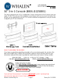
50” 3-in-1 Console (BBXLO2250BS)
This item is designed to be a 3-in-1 configuration. Please choose which of the 3 options suits your
needs. DO NOT discard any of the hardware or parts that you will not use on your set option, this
will give you the opportunity to use this TV Console for different configurations in case you decide
to upgrade your TV set in the future.
ADULT ASSEMBLY REQUIRED
If you have any questions regarding assembly or if you are missing parts, do not return this
item to the retailer store. Please call our toll-free customer service number and have your
instructions and parts list ready to provide the model name, part name or factory number:
1-866-942-5362 8:30 a.m. - 4:30 p.m. PST, Monday - Friday
Video Instruction Guides
Go to http://whalen.showuhow.com to view step-by-step instructional
videos for assembling and installing your product. Enter the following
product number on the ShowUhow homepage.
LOT NUMBER:
DATE PURCHASED: / /
BBXLO2250BS

Model # BBXLO2250BS
Please call for replacement parts or assistance: 1-866-942-5362
Whalen Furniture Mfg. Inc. Page 2 Factory No. 55-12029
MANUFACTURER: Whalen Furniture
CATALOG: 50” 3-in-1 Console (BBXLO2250BS)
DATE OF MANUFACTURE: April, 2011
MADE IN CHINA
1. Please read the Assembly Instructions prior to assembling this product.
2. Remove all hardware from box and sort by size.
3. Check to see that all hardware and parts are present BEFORE assembling.
4. Ask a friend to assist you with the assembly of this furniture.
5. To avoid damage, assemble the product on a sturdy, level and protective surface.
6. Please wait until all steps are completed before tightening bolts.
7. Make sure all bolts are tightly fastened before the unit is used.
MAXIMUM RECOMMENDED WEIGHT LOADS
GENERAL INFORMATION, TIPS & TRICKS
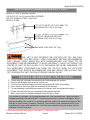
This product is sold with Tip Restraint Hardware kit. You must install the Tipping Restraint
Hardware between the wall and the TV stand to prevent any accidents or damages. When
properly installed, this restraint can provide protection against the unexpected tipping of the
unit due to small tremors, bumps or climbing. The restraint is only a deterrent and is not a
substitute for proper adult supervision. Use of tip-over restraints may only reduce, but not
eliminate, the risk of tip-over.
FITS UP TO MOST 56” FLAT PANEL TVs
WITHOUT SWIVELING BRACKET
MAXIMUM LOAD 135 lb. (61.2 kg)
THIS UNIT IS NOT INTENDED FOR USE WITH CRT TVS. USE ONLY
WITH FLAT PANEL TVS AND AUDIO / VIDEO EQUIPMENT MEETING RECOMMENDED
SIZE / WEIGHT LIMITS. NEVER USE WITH LARGER/HEAVIER FLAT PANEL TVS OR
EQUIPMENT THAN RECOMMENDED. TO AVOID INSTABILITY, PLACE FLAT PANEL TV IN
CENTER OF UNIT; DO NOT ALLOW TV TO OVERHANG UNIT IN ANY DIMENSION. CRT
TVS, IMPROPERLY POSITIONED FLAT PANEL TVS, OR FLAT PANEL TVS OR OTHER
EQUIPMENT THAT EXCEED RECOMMENDED SIZE AND WEIGHT LIMITS COULD FALL
OFF OR BREAK THE UNIT, CAUSING POSSIBLE SERIOUS INJURY.
FITS UP TO MOST 56” FLAT PANEL TVs
MAXIMUM LOAD 135 lb. (61.2 kg)
MAXIMUM LOAD 50 lb. (22.7 kg)

Model # BBXLO2250BS
Please call for replacement parts or assistance: 1-866-942-5362
Whalen Furniture Mfg. Inc. Page 3 Factory No. 55-12029
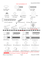
Parts and Hardware List
Please read completely through the instructions and verify that all parts listed are present
before beginning assembly.
A-Top Shelf Frame (1) B- Middle Shelf Frame (1)
C- Bottom Shelf Frame (1) D- Long Spine (1)
D1- Short Spine (1) E- Left Leg (1) F- Right Leg (1)
G- Top Glass (1) H- Middle Glass Shelf (1)
I- Bottom Glass Shelf (1) J- Swiveling Bracket (1)
K- XYZ Mounting Frame (1) L- Monitor Bracket (L/R) (2) M- Cable Control (2)
LR
LL

Model # BBXLO2250BS
Please call for replacement parts or assistance: 1-866-942-5362
Whalen Furniture Mfg. Inc. Page 4 Factory No. 55-12029
Parts and Hardware List
(1) Suction Cup (2) 3/4” Bolt (3) 1-1/4” Bolt
(12+1 extra) (34+1 extra) (4+1 extra)
(4) Hex Nut (5) Lock Washer (6) Flat Washer (7) Large Flat Washer
(4+1 extra) (34+1 extra) (38+1 extra) (6+1 extra)
(8) 2-1/2” Lag Bolt (6) (9) Concrete Anchor (6) (10) Glass Riser (8+1 extra)
Open Wrench M4 Allen Wrench 3/16” Allen Wrench Tipping Restraint Hardware Kit (1)
(1) (2) (1) (Inside Plastic Bag)
TV Mounting Kit
M4 x 12 Bolt (4) M4 x 30 Bolt (4) M5 X 12 Bolt (4) M5 x 30 Bolt (4)
M6 x12 Bolt (4) M6 x 35 Bolt (4) M8x16 Bolt (4) M8 x40 Bolt (4)
M4 Lock Washer (4) M5 Lock Washer (4) M6 Lock Washer (4) M8 Lock Washer (4)
Large Spacer (4) Small Spacer (4) M4/M5 Flat Washer (8) M6/M8 Flat Washer (4)
Tools required: Allen Wrench, Open Wrench (provided) and Phillips Screwdriver (not provided).

Model # BBXLO2250BS
Please call for replacement parts or assistance: 1-866-942-5362
Whalen Furniture Mfg. Inc. Page 5 Factory No. 55-12029
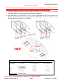
Assembly Instructions
Note: Please do not fully tighten all bolts until you finish assembling all parts. Once assembled,
go back and fully tighten all bolts. This will make it easier during assembly of unit.
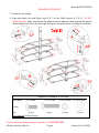
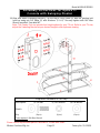
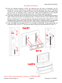
1. Choose the option suits your needs. Locate Long Spine (D) or Short Spine (D1) and set
back face down on a scratch free surface as shown in detail #1.
2. Align and attach 3 Shelf Frames (A, B & C) to the Spine using the 3/4” Bolts (2) with Lock
Washers & Flat Washers (5 & 6) through the pre-drilled holes on the “U” Bracket into the
threaded holes on the Spine. See detail #1.
Required hardware in this step
Description: (2) 3/4” Bolt (5) Lock Washer (6) Flat Washer
Sketch
Qty. (12 pcs) (12 pcs) (12 pcs)
Tools required: M4 Allen Wrench

Model # BBXLO2250BS
Please call for replacement parts or assistance: 1-866-942-5362
Whalen Furniture Mfg. Inc. Page 6 Factory No. 55-12029
Assembly Instructions
3. Stand the unit upright.
4. Align and attach Left and Right Legs (E & F) to the Shelf Frames (A, B & C). DO NOT
tighten the bolts. Make sure that the top edges are even with each other and that the gaps &
offsets between the front rails and Legs are equal. Loosen the bolts and adjust if necessary.
Required hardware in this step
Description: (2) 3/4” Bolt (3) 1-1/4” Bolt (5) Lock Washer (6) Flat Washer
Sketch
Qty. (8 pcs) (4 pcs) (12 pcs) (12 pcs)
Tools required: M4 Allen Wrench

Model # BBXLO2250BS
Please call for replacement parts or assistance: 1-866-942-5362
Whalen Furniture Mfg. Inc. Page 7 Factory No. 55-12029
Assembly Instructions
5. Go back and tighten all bolts with M4 Allen Wrench provided.
6. Adjust the Floor Levelers pre-attached at the bottom of both Legs (E & F) to level the TV
stand as shown in detail #3.
Hardware provided Tools required
Pre-attached Floor Leveler No tool required
If you choose Table-top configuration,
continue to STEP 7.
If mounting TV with the Swinging Floater,
skip ahead to PAGE 11.

Model # BBXLO2250BS
Please call for replacement parts or assistance: 1-866-942-5362
Whalen Furniture Mfg. Inc. Page 8 Factory No. 55-12029
Assembly Instructions for Table-top
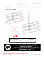
7. Attach 2 Cable Controls (M) onto the backside of Short Spine (D1) with the 3/4” Bolts (2)
and tighten with enclosed M4 Allen Wrench. See detail #4.
8. The Cable Controls (M) allow you to organize, route and separate your component cords
and cables to minimize tangling and signal interference. As shown in detail #4.
Required hardware in this step
Description: (2) 3/4” Bolt (M) Cable Control
Sketch
Qty. (4 pcs) (2 pcs)
Tools required: M4 Allen Wrench

Model # BBXLO2250BS
Please call for replacement parts or assistance: 1-866-942-5362
Whalen Furniture Mfg. Inc. Page 9 Factory No. 55-12029
Assembly Instructions for Table-top
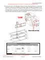
9. Put Suction Cups (1) firmly into the top holes and metal tabs on Shelf Frames (B & C) as
shown in detail #5.
10. Screw 8 Glass Risers (10) onto the top holes of Top Shelf Frame (A) & both Legs (E & F).
Make sure they go all the way in. See detail #5.
11. Place Top Glass (G) & Glass Shelves (H & I) in place starting from the Bottom Glass Shelf (I)
as shown in detail #6. Make sure the glass is properly centered and the black side of glass
is down. Push each glass all the way back against the Spine. Also, be sure to press down
evenly and firmly each glass onto the Suction Cups or Glass Raisers to make sure they
securely rest onto the Suction Cups.
Note: Make sure that the Suction Cups go all the way into the pre-drilled holes to prevent
the glass shelf from falling and getting damage. If glass is scratched you can minimize the
damage by using a BLACK marker and filling in scratched area from underneath.
Required hardware in this step
Description: (1) Suction Cup (10) Glass Riser
Sketch
Qty. (12 pcs) (8 pcs)
Tools required: No tool required

Model # BBXLO2250BS
Please call for replacement parts or assistance: 1-866-942-5362
Whalen Furniture Mfg. Inc. Page 10 Factory No. 55-12029
Assembly Instructions for Table-top
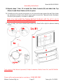
12. Position the assembled Table-top in your desired location against the wall. Now follow the
instructions printed on the plastic bag in order to mount the Tipping Restraint Hardware Kit
to the Spine properly. As shown in detail #6.
NOTE: YOU MUST USE THIS TIPPING RESTRAINT TO ATTACH THIS UNIT TO
THE WALL, TO PREVENT ACCIDENTS AND/OR INJURIES.
13. The Table-top is ready for use now. Be sure to position your Flat Panel TV in center of
console with no overhang on either side.
Tools required: Allen Wrench (provided), Phillips Screwdriver, Mallet, Power Drill, and 3/8” Drill Bit.

Model # BBXLO2250BS
Please call for replacement parts or assistance: 1-866-942-5362
Whalen Furniture Mfg. Inc. Page 11 Factory No. 55-12029
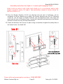
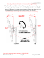
14. Align and attach Swiveling Bracket (J) to the top of Long Spine (D) with the pivoting bolt
head up using six 3/4” Bolts (2) with Washers (5 & 6). Securely tighten with M4 Allen
Wrench provided. See detail #7.
Note: The Floater Post can provide four height options for your TV set. Refer to your TV size,
adjust the Swiveling Bracket at your desired height to offer optimum viewing.
Assembly Instructions for Option 1:
Console with Swinging Floater
Required hardware in this step
Description: (2) 3/4” Bolt (5) Lock Washer (6) Flat Washer
Sketch
Qty. (6 pcs) (6 pcs) (6 pcs)
Tools required: M4 Allen Wrench

Model # BBXLO2250BS
Please call for replacement parts or assistance: 1-866-942-5362
Whalen Furniture Mfg. Inc. Page 12 Factory No. 55-12029
Assembly Instructions for Option 1: Console with Swinging Floater
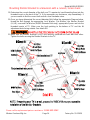
15. Hold the flat side of XYZ Mounting Frame (K) onto the Swiveling Bracket (J) ensuring the
recessed 2 holes on the Mounting Frame bottom. Align and attach by threading four 3/4”
Bolts (2) with Flat Washers (6) through the metal plate on XYZ Mounting Frame and the
Swiveling Bracket, at the other side of Swiveling Bracket fit the other Flat Washers (6) and
Lock Washers (5) onto the Bolts, and then secure with Nuts (4). Securely tighten with Open
Wrench and M4 Allen Wrench provided. See detail #8.
Required hardware in this step
Description: (2) 3/4” Bolt (4) Hex Nut (5) Lock Washer (6) Flat Washer
Sketch
Qty. (4 pcs) (4 pcs) (4 pcs) (8 pcs)
Tools required: M4 Allen Wrench and Open Wrench

Model # BBXLO2250BS
Please call for replacement parts or assistance: 1-866-942-5362
Whalen Furniture Mfg. Inc. Page 13 Factory No. 55-12029
Mounting Monitor Bracket to a television with a flat back
Note: For televisions with a curved back or recessed back proceed directly to step #19.
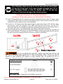
16. Determine the correct diameter of the bolt your TV requires by hand threading them into the
threaded insert on the back of the TV. If you encounter any resistance, stop immediately. If
you are unable to find the correct bolt consult a local hardware store.
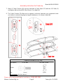
17. Once you have determined the correct diameter Bolt, follow the appropriate diagram below;
thread the Short Bolt through the appropriate Lock Washer, Flat Washer, the Monitor Bracket
(LL/LR), and into the upper threaded inserts of TV. Make sure the hook pointing towards the
bottom of TV and the tilt adjustment knob facing outside. As shown in detail #9A. Note: Lean
the TV up against a wall or other solid surface when attaching with the Monitor Brackets. DO
NOT place the TV face down on the glass this may cause permanent damage.
18. Proceed to insert the long Bolt through the appropriate Lock Washer, the Flat Washer, the
slot of Monitor Bracket (LL/LR), a second Flat Washer (M4/M5 Diameter Bolts only),
appropriate Spacer, and into the bottom threaded inserts of TV. As shown in detail #9. Make
sure the Monitor Brackets (LL/LR) are centered and level with each other. Tighten the bolts
securing the Monitor Brackets to the TV.

Model # BBXLO2250BS
Please call for replacement parts or assistance: 1-866-942-5362
Whalen Furniture Mfg. Inc. Page 14 Factory No. 55-12029
Mounting Monitor Bracket to a television with a curved / recess back
19. Determine the correct diameter of the bolt your TV requires by hand threading them into the
threaded insert on the back of the TV. If you encounter any resistance, stop immediately. If
you are unable to find the correct bolt consult a local hardware store.
20. Once you have determined the correct diameter Bolt, follow the appropriate Diagram below,
thread the Bolt through the appropriate Lock Washer, Flat Washer, the Monitor Bracket
(LL/LR), a second Flat Washer (M4/M5 Diameter Bolts only), appropriate Spacer and into the
threaded inserts of TV. Make sure the hook pointing to the bottom of TV and the tilt
adjustment knob facing outside. See detail #10.
21. Make sure the Monitor Brackets (LL/LR) are vertically centered and level with each other.
Tighten the bolts securing the Monitor Brackets to the TV.

Model # BBXLO2250BS
Please call for replacement parts or assistance: 1-866-942-5362
Whalen Furniture Mfg. Inc. Page 15 Factory No. 55-12029
Assembly Instructions for Option 1: Console with Swinging Floater
MAKE SURE ALL BOLTS ARE TIGHT AND SPINE IS AT A 90 DEGREE ANGLE AND
USING A QUALITY LEVEL TO VERIFY THE MOUNTING FRAME IS LEVEL PRIOR TO
INSTALLATION OF TV.
22. Once the Monitor Brackets (LL/LR) are attached onto the back of television, ask for
assistance to lift the television up to attach the Monitor Brackets onto the XYZ Mounting
Frame (K). Set the hooks on Monitor Brackets over the Mounting Frame, then lower the
hooks onto the bars of Mounting Frame. Loosen the Safety Bolt pre-attached on the Monitor
Brackets to ensure an easy fit at the bottom hooks.
23. Center the television, then secure it in place using a screwdriver to tighten the safety bolts on
the bottom hooks. See detail #11.

Model # BBXLO2250BS
Please call for replacement parts or assistance: 1-866-942-5362
Whalen Furniture Mfg. Inc. Page 16 Factory No. 55-12029
Assembly Instructions for Option 1: Console with Swinging Floater
24. The Monitor Brackets (LL/LR) can tilt up to 11˚ downward and 5˚ upward, depending on your
optimum viewing position. Have your assistant hold the TV steady before you start to adjust
the tilt. Simply reach behind the TV and turn the both Tilt Adjustment Knobs with 3/16” Allen
Wrench to adjust your TV to provide optimum viewing and minimize glare. When the TV is in
its intended position, tighten both lock bolts to secure it in place. See detail #12.
Note: If you need to remove the TV, make sure both Lock Bolts are disengaged fully.

Model # BBXLO2250BS
Please call for replacement parts or assistance: 1-866-942-5362
Whalen Furniture Mfg. Inc. Page 17 Factory No. 55-12029
Assembly Instructions
25. Repeat steps 7 thru 11 to install the Cable Controls (M) and attach the Top
Glass (G) and Glass Shelves (H & I) in place.
26. Carefully move the console and position in your desired location against the wall. Now follow
the instructions printed on the plastic bag in order to mount the Tipping Restraint Hardware
Kit to the Spine properly. As shown in detail #13.
Note: You must install the Tipping Restraint Hardware with the unit in use to
prevent any accidents or damage to the unit.
27. You can enjoy your home entertainment center now. Swivel left-or-right for optimum viewing
control.
Tools required: Allen Wrench (provided), Phillips Screwdriver, Mallet, Power Drill, and 3/8” Drill Bit.

Model # BBXLO2250BS
Please call for replacement parts or assistance: 1-866-942-5362
Whalen Furniture Mfg. Inc. Page 18 Factory No. 55-12029
Assembly Instructions for Universal Wall Mount
Installing XYZ Mounting Frame onto WOODEN STUD WALL
28. The XYZ Mounting Frame (K) must be mounted to two Wood Studs at least 12” apart, using
a high quality Stud Finder to locate the two adjacent studs. After you have located the studs,
verify with a nail for added security. See detail #14A.
29. Pre-drill a 2-1/2" deep hole at the desired height in each stud using a 3/16” drill bit, make
sure that the holes are centered in the studs and level with each other. Use the XYZ
Mounting Frame (K) as a template to mark the corresponding location for the bottom holes in
each stud, drill holes 2-1/2" deep with the 3/16” drill bit at the marked location.
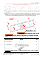
30. Orient the Mounting Frame with the slotted plate against the wall, and using four Lag Bolts (8)
with Lag Bolt Washer (7) through the slots of “Z” Plate on Mounting Frame into the holes in
the wall, secure the mounting frame to the wall as shown in detail #14B.
Do not over tighten the Lag Bolts. Tighten Lag Bolts only until the Lag
Bolt Washer is pulled firmly against the “Z” Plate of Mounting Frame. If there is a layer of
drywall or other material, this drywall or other material may not exceed 5/8 inch in
thickness. Failure to heed this caution may result property damage and/or personal injury.
The following steps are only for those who wish to mount their
TV directly to the wall. If you have already mounted your TV to
the Swinging Floater or plan to display your TV on the top
surface of the stand, disregard the following steps.
Hardware provided Sketch Qty.
(7) Lag Bolt Washer (4)
(8) 2-1/2” Lag Bolt (4)
Tools required
Stud Sensor, Mallet, Power Drill, 3/16” Drill Bit, Socket Set

Model # BBXLO2250BS
Please call for replacement parts or assistance: 1-866-942-5362
Whalen Furniture Mfg. Inc. Page 19 Factory No. 55-12029
Assembly Instruction for installing XYZ Mounting Frame onto BRICK, SOLID
CONCRETE OR CONCRETE BLOCK
31. Use the XYZ Mounting Frame (K) as a template, mark six holes location on the wall, three in
the top row and three in the bottom row of slots. Make sure that the holes are level and there
is at least 6” between any two holes, pre-drill these holes with a 1/2” masonry bit to at least
2-1/2” in depth.
32. Insert a Concrete Anchor (9) into each of these holes; make sure they are completely seated
and flush with the concrete surface, even if there is a layer of drywall or other material in front
of the concrete.
33. Orient and attach the XYZ Mounting Frame (K) to the wall using six Lag Bolts (8) and Lag
Bolt Washers (7) through the slot of “Z” Plate on Mounting Frame into the Concrete Anchors
(9) in the wall as shown in detail #15. Make sure the slotted plates against the wall.
Concrete Anchors should only be used for masonry mounting.
NEVER use the wall anchors to mount the unit to drywall.
Hardware provided Sketch Qty.
(7) Lag Bolt Washer (6)
(8) 2-1/2” Lag Bolt (6)
(9) Concrete Anchor (6)
Tools required: Mallet, Power Drill, 1/2” Masonry Bit for brick concrete, Socket Set and level.
Maximum weight 165 lb. (74.8 kg)

Model # BBXLO2250BS
Please call for replacement parts or assistance: 1-866-942-5362
Whalen Furniture Mfg. Inc. Page 20 Factory No. 55-12029
Assembly Instructions
34. Once the Monitor Brackets (LL/OR) are attached onto the back of television, ask for
assistance to lift the television up to attach the Monitor Brackets onto the XYZ Mounting
Frame (K). Set the hooks on Monitor Brackets over the Mounting Frame then lower them
onto the bars of Mounting Frame. Loosen the Safety Bolt pre-attached on the Monitor
Brackets to ensure an easy fit at the bottom hooks. Proceed to center the television.
35. If you want to adjust the tilt, ask for help from your friends to hold the TV steady before you start to
adjust. Simply turn the both Tilt Adjustment Knobs on Monitor Brackets (LL/LR) with 3/16” Allen
Wrench to adjust your TV to provide optimum viewing and minimize glare. When the TV is in its
intended position, tighten both safety bolts with a long Phillips Screwdriver until they hit underside
of XYZ Mounting Frame (K) to ensure your TV is safe and secure on the wall. See detail #16.
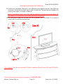
36. Place assembled console under your TV set as shown in detail #16A. Finally, connect the A/V
and power cables to your TV. You are now ready to enjoy your wall-mounted Flat Panel TV.
Page is loading ...
Page is loading ...
-
 1
1
-
 2
2
-
 3
3
-
 4
4
-
 5
5
-
 6
6
-
 7
7
-
 8
8
-
 9
9
-
 10
10
-
 11
11
-
 12
12
-
 13
13
-
 14
14
-
 15
15
-
 16
16
-
 17
17
-
 18
18
-
 19
19
-
 20
20
-
 21
21
-
 22
22


Whalen BBXLO2250BS User manual
- Category
- Flat panel wall mounts
- Type
- User manual
Ask a question and I''ll find the answer in the document
Finding information in a document is now easier with AI


