Page is loading ...

USER GUIDE
Gateway® E-9425R Server


i
Chapter 1: Checking Out Your Gateway Server . . . . . . . . . . . . . . . . . . . . . . . . . . . . . . . .1
Front . . . . . . . . . . . . . . . . . . . . . . . . . . . . . . . . . . . . . . . . . . . . . . . . . . . . . . . . . . . . . . . . . . . . 2
Control panel . . . . . . . . . . . . . . . . . . . . . . . . . . . . . . . . . . . . . . . . . . . . . . . . . . . . . . . . 2
Back . . . . . . . . . . . . . . . . . . . . . . . . . . . . . . . . . . . . . . . . . . . . . . . . . . . . . . . . . . . . . . . . . . . . 3
Interior . . . . . . . . . . . . . . . . . . . . . . . . . . . . . . . . . . . . . . . . . . . . . . . . . . . . . . . . . . . . . . . . . . 4
System board . . . . . . . . . . . . . . . . . . . . . . . . . . . . . . . . . . . . . . . . . . . . . . . . . . . . . . . . . . . 5
Connectors . . . . . . . . . . . . . . . . . . . . . . . . . . . . . . . . . . . . . . . . . . . . . . . . . . . . . . . . . . 5
Hot-swap backplanes . . . . . . . . . . . . . . . . . . . . . . . . . . . . . . . . . . . . . . . . . . . . . . . . . . . . 7
SAS/SATA backplane . . . . . . . . . . . . . . . . . . . . . . . . . . . . . . . . . . . . . . . . . . . . . . . . . 7
LED information . . . . . . . . . . . . . . . . . . . . . . . . . . . . . . . . . . . . . . . . . . . . . . . . . . . . . 8
Getting Help . . . . . . . . . . . . . . . . . . . . . . . . . . . . . . . . . . . . . . . . . . . . . . . . . . . . . . . . . . . . 9
Server Companion DVD . . . . . . . . . . . . . . . . . . . . . . . . . . . . . . . . . . . . . . . . . . . . . . 9
Gateway Web site . . . . . . . . . . . . . . . . . . . . . . . . . . . . . . . . . . . . . . . . . . . . . . . . . . . 9
Telephone support . . . . . . . . . . . . . . . . . . . . . . . . . . . . . . . . . . . . . . . . . . . . . . . . . . 9
Chapter 2: Setting Up Your Server . . . . . . . . . . . . . . . . . . . . . . . . . . . . . . . . . . . . . . . . . . 11
Setting up the hardware . . . . . . . . . . . . . . . . . . . . . . . . . . . . . . . . . . . . . . . . . . . . . . . . 12
Protecting from power source problems . . . . . . . . . . . . . . . . . . . . . . . . . . . . . . . . 12
Mounting your server into a cabinet . . . . . . . . . . . . . . . . . . . . . . . . . . . . . . . . . . . . 13
Installing the bezel . . . . . . . . . . . . . . . . . . . . . . . . . . . . . . . . . . . . . . . . . . . . . . . . . 16
Removing the server from a cabinet . . . . . . . . . . . . . . . . . . . . . . . . . . . . . . . . 17
Starting your server . . . . . . . . . . . . . . . . . . . . . . . . . . . . . . . . . . . . . . . . . . . . . . . . . . . . 18
Understanding the power-on self-test . . . . . . . . . . . . . . . . . . . . . . . . . . . . . . . 19
Turning off your server . . . . . . . . . . . . . . . . . . . . . . . . . . . . . . . . . . . . . . . . . . . . . 19
Setting up the operating system . . . . . . . . . . . . . . . . . . . . . . . . . . . . . . . . . . . . . . . . 19
Initial hardware settings . . . . . . . . . . . . . . . . . . . . . . . . . . . . . . . . . . . . . . . . . . . . . . . . 19
Chapter 3: Maintaining Your Server . . . . . . . . . . . . . . . . . . . . . . . . . . . . . . . . . . . . . . . . . 21
Caring for your server . . . . . . . . . . . . . . . . . . . . . . . . . . . . . . . . . . . . . . . . . . . . . . . . . . 22
Cleaning your server . . . . . . . . . . . . . . . . . . . . . . . . . . . . . . . . . . . . . . . . . . . . . . . . 22
Preparing for system recovery . . . . . . . . . . . . . . . . . . . . . . . . . . . . . . . . . . . . . . . . . . 23
Recording the BIOS configuration . . . . . . . . . . . . . . . . . . . . . . . . . . . . . . . . . . . 23
System administration . . . . . . . . . . . . . . . . . . . . . . . . . . . . . . . . . . . . . . . . . . . . . . . . . . 24
Gateway System Manager . . . . . . . . . . . . . . . . . . . . . . . . . . . . . . . . . . . . . . . . . . 24
Server security . . . . . . . . . . . . . . . . . . . . . . . . . . . . . . . . . . . . . . . . . . . . . . . . . . . . . . 24
Identifying your server . . . . . . . . . . . . . . . . . . . . . . . . . . . . . . . . . . . . . . . . . . . . . . . . . 25
Updating the baseboard management controller firmware . . . . . . . . . . . . . . 25
Using your Server Companion DVD . . . . . . . . . . . . . . . . . . . . . . . . . . . . . . . . . . . . . 26
Server Companion DVD contents . . . . . . . . . . . . . . . . . . . . . . . . . . . . . . . . . . . 26
Viewing documents . . . . . . . . . . . . . . . . . . . . . . . . . . . . . . . . . . . . . . . . . . . . . . . . 26
Installing drivers and programs . . . . . . . . . . . . . . . . . . . . . . . . . . . . . . . . . . . . . 27
Updating the BIOS and firmware . . . . . . . . . . . . . . . . . . . . . . . . . . . . . . . . . . . . 27
Booting the Server Companion DVD . . . . . . . . . . . . . . . . . . . . . . . . . . . . . . . . 28
Contents

Contents www.gateway.com
ii
Chapter 4: Installing Components . . . . . . . . . . . . . . . . . . . . . . . . . . . . . . . . . . . . . . . . . . .29
Preparing to install components . . . . . . . . . . . . . . . . . . . . . . . . . . . . . . . . . . . . . . . .30
Selecting a place to work . . . . . . . . . . . . . . . . . . . . . . . . . . . . . . . . . . . . . . . . . . . .30
Gathering the tools you need . . . . . . . . . . . . . . . . . . . . . . . . . . . . . . . . . . . . . . .30
Getting Help . . . . . . . . . . . . . . . . . . . . . . . . . . . . . . . . . . . . . . . . . . . . . . . . . . . . . . . .30
Preventing static electricity discharge . . . . . . . . . . . . . . . . . . . . . . . . . . . . . . . . . . .30
Opening the server case . . . . . . . . . . . . . . . . . . . . . . . . . . . . . . . . . . . . . . . . . . . . . . . .31
Closing the server case . . . . . . . . . . . . . . . . . . . . . . . . . . . . . . . . . . . . . . . . . . . . . . . . . .32
Installing and removing drives . . . . . . . . . . . . . . . . . . . . . . . . . . . . . . . . . . . . . . . . . .33
Removing and installing an optical drive . . . . . . . . . . . . . . . . . . . . . . . . . . . . .33
Removing and installing a hard drive . . . . . . . . . . . . . . . . . . . . . . . . . . . . . . . .36
Installing an optional diskette drive . . . . . . . . . . . . . . . . . . . . . . . . . . . . . . . . . .37
Filling empty drive bays . . . . . . . . . . . . . . . . . . . . . . . . . . . . . . . . . . . . . . . . . . . . .38
Installing memory . . . . . . . . . . . . . . . . . . . . . . . . . . . . . . . . . . . . . . . . . . . . . . . . . . . . . .39
Non-redundant mode . . . . . . . . . . . . . . . . . . . . . . . . . . . . . . . . . . . . . . . . . . . . . . .40
Mirroring mode: . . . . . . . . . . . . . . . . . . . . . . . . . . . . . . . . . . . . . . . . . . . . . . . . . . . . .41
Sparing mode . . . . . . . . . . . . . . . . . . . . . . . . . . . . . . . . . . . . . . . . . . . . . . . . . . . . . . .41
Installing and removing PCI expansion cards . . . . . . . . . . . . . . . . . . . . . . . . . . . .43
Removing and installing the PCI riser assembly, a riser, or PCI card . . .43
Replacing system fans . . . . . . . . . . . . . . . . . . . . . . . . . . . . . . . . . . . . . . . . . . . . . . . . . .46
Replacing or adding a processor . . . . . . . . . . . . . . . . . . . . . . . . . . . . . . . . . . . . . . . .48
Replacing a power supply module . . . . . . . . . . . . . . . . . . . . . . . . . . . . . . . . . . . . . .51
Replacing the power distribution board . . . . . . . . . . . . . . . . . . . . . . . . . . . . . . . . .52
Replacing the power cage . . . . . . . . . . . . . . . . . . . . . . . . . . . . . . . . . . . . . . . . . . . . . .53
Replacing the hot-swap backplanes . . . . . . . . . . . . . . . . . . . . . . . . . . . . . . . . . . . . .54
Replacing the ROMB battery pack for the mezzanine RAID card . . . . . . . . . .55
Installing and removing an optional mezzanine board . . . . . . . . . . . . . . . . . . .56
Replacing the CMOS battery . . . . . . . . . . . . . . . . . . . . . . . . . . . . . . . . . . . . . . . . . . . .57
Replacing the control panel . . . . . . . . . . . . . . . . . . . . . . . . . . . . . . . . . . . . . . . . . . . . .58
Replacing the system board . . . . . . . . . . . . . . . . . . . . . . . . . . . . . . . . . . . . . . . . . . . . .59
Chapter 5: Using the BIOS Setup Utility . . . . . . . . . . . . . . . . . . . . . . . . . . . . . . . . . . . . . .63
Opening the BIOS Setup utility . . . . . . . . . . . . . . . . . . . . . . . . . . . . . . . . . . . . . . . . . .64
Updating the BIOS . . . . . . . . . . . . . . . . . . . . . . . . . . . . . . . . . . . . . . . . . . . . . . . . . . . . . .64
Recovering the BIOS . . . . . . . . . . . . . . . . . . . . . . . . . . . . . . . . . . . . . . . . . . . . . . . . . . . .65
Resetting the BIOS . . . . . . . . . . . . . . . . . . . . . . . . . . . . . . . . . . . . . . . . . . . . . . . . . . . . . .66
Resetting BIOS passwords . . . . . . . . . . . . . . . . . . . . . . . . . . . . . . . . . . . . . . . . . . .68
Chapter 6: Troubleshooting . . . . . . . . . . . . . . . . . . . . . . . . . . . . . . . . . . . . . . . . . . . . . . . . .69
Telephone support . . . . . . . . . . . . . . . . . . . . . . . . . . . . . . . . . . . . . . . . . . . . . . . . . . . . .70
Before calling Gateway Customer Care . . . . . . . . . . . . . . . . . . . . . . . . . . . . . . .70
Telephone support . . . . . . . . . . . . . . . . . . . . . . . . . . . . . . . . . . . . . . . . . . . . . . . . . .71
Tutoring and training . . . . . . . . . . . . . . . . . . . . . . . . . . . . . . . . . . . . . . . . . . . . . . . . . . .71
Safety guidelines . . . . . . . . . . . . . . . . . . . . . . . . . . . . . . . . . . . . . . . . . . . . . . . . . . . . . . . .72
Error messages . . . . . . . . . . . . . . . . . . . . . . . . . . . . . . . . . . . . . . . . . . . . . . . . . . . . . . . . .72

Contents
www.gateway.com
iii
Troubleshooting . . . . . . . . . . . . . . . . . . . . . . . . . . . . . . . . . . . . . . . . . . . . . . . . . . . . . . . 77
First steps . . . . . . . . . . . . . . . . . . . . . . . . . . . . . . . . . . . . . . . . . . . . . . . . . . . . . . . . . . 77
Battery replacement . . . . . . . . . . . . . . . . . . . . . . . . . . . . . . . . . . . . . . . . . . . . . . . . 77
Beep codes . . . . . . . . . . . . . . . . . . . . . . . . . . . . . . . . . . . . . . . . . . . . . . . . . . . . . . . . . 78
LED information . . . . . . . . . . . . . . . . . . . . . . . . . . . . . . . . . . . . . . . . . . . . . . . . . . . . 79
Diagnostic LEDs . . . . . . . . . . . . . . . . . . . . . . . . . . . . . . . . . . . . . . . . . . . . . . . . . . . . 81
BIOS . . . . . . . . . . . . . . . . . . . . . . . . . . . . . . . . . . . . . . . . . . . . . . . . . . . . . . . . . . . . . . . . 86
Optical drive . . . . . . . . . . . . . . . . . . . . . . . . . . . . . . . . . . . . . . . . . . . . . . . . . . . . . . . . 87
Expansion cards . . . . . . . . . . . . . . . . . . . . . . . . . . . . . . . . . . . . . . . . . . . . . . . . . . . . 87
Hard drive . . . . . . . . . . . . . . . . . . . . . . . . . . . . . . . . . . . . . . . . . . . . . . . . . . . . . . . . . . 87
Internet . . . . . . . . . . . . . . . . . . . . . . . . . . . . . . . . . . . . . . . . . . . . . . . . . . . . . . . . . . . . 88
Keyboard . . . . . . . . . . . . . . . . . . . . . . . . . . . . . . . . . . . . . . . . . . . . . . . . . . . . . . . . . . . 88
Memory . . . . . . . . . . . . . . . . . . . . . . . . . . . . . . . . . . . . . . . . . . . . . . . . . . . . . . . . . . . . 88
Monitor . . . . . . . . . . . . . . . . . . . . . . . . . . . . . . . . . . . . . . . . . . . . . . . . . . . . . . . . . . . . 89
Power . . . . . . . . . . . . . . . . . . . . . . . . . . . . . . . . . . . . . . . . . . . . . . . . . . . . . . . . . . . . . . 89
Processor . . . . . . . . . . . . . . . . . . . . . . . . . . . . . . . . . . . . . . . . . . . . . . . . . . . . . . . . . . . 90
Appendix A: Server Specifications . . . . . . . . . . . . . . . . . . . . . . . . . . . . . . . . . . . . . . . . . . 91
System specifications . . . . . . . . . . . . . . . . . . . . . . . . . . . . . . . . . . . . . . . . . . . . . . . . . . . 92
System board specifications . . . . . . . . . . . . . . . . . . . . . . . . . . . . . . . . . . . . . . . . . . . . 92
Environmental specifications . . . . . . . . . . . . . . . . . . . . . . . . . . . . . . . . . . . . . . . . . . . 93
Electronic specifications . . . . . . . . . . . . . . . . . . . . . . . . . . . . . . . . . . . . . . . . . . . . . . . . 94
Memory map . . . . . . . . . . . . . . . . . . . . . . . . . . . . . . . . . . . . . . . . . . . . . . . . . . . . . . . 94
Interrupts . . . . . . . . . . . . . . . . . . . . . . . . . . . . . . . . . . . . . . . . . . . . . . . . . . . . . . . . . . . 94
Connector pinouts . . . . . . . . . . . . . . . . . . . . . . . . . . . . . . . . . . . . . . . . . . . . . . . . . . 95
Additional specifications . . . . . . . . . . . . . . . . . . . . . . . . . . . . . . . . . . . . . . . . . . . . . . . 98
Appendix B: BIOS Settings. . . . . . . . . . . . . . . . . . . . . . . . . . . . . . . . . . . . . . . . . . . . . . . . . . 99
Appendix C: Safety, Regulatory, and Legal Information . . . . . . . . . . . . . . . . . . . . . 111
Index. . . . . . . . . . . . . . . . . . . . . . . . . . . . . . . . . . . . . . . . . . . . . . . . . . . . . . . . . . . . . . . . . . . . . 117

Contents www.gateway.com
iv


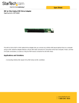
Back
www.gateway.com
3
Back
Dual NIC
connectors
Server
management
port
PS/2 keyboard
connector
PS/2 mouse
connector
VGA
connector
ID LED
Serial port
SAS JBOD connector
(optional
Dual USB
connectors
AC power
connector

CHAPTER 1: Checking Out Your Gateway Server www.gateway.com
4
Interior
# Feature # Feature
1 System board 7 Slimline DVD/CD-RW combo
drive or DVD-RW drive
2System fans 8SAS/SATA backplane
3 Fan board 9 ROMB battery backup
4 Hard drive bays 10 Riser card assembly
5 SMIL module (optional) 11 Power supply bay
6 Control panel

System board
www.gateway.com
5
System board
Connectors
28
29
30
31
32
33
34
35
37
36
# Feature # Feature
1 Rear dual USB Port (J35) 20 DIMM7 socket (J24)
2 Serial port (J31) 21 DIMM8 socket (J25)
3 ID LED (CR16) 22 Fan power/fan tach connector (J99)

CHAPTER 1: Checking Out Your Gateway Server www.gateway.com
6
4 VGA port (J39) 23 Processor 1 (CPU1) socket
5 PS/2 mouse port (J15) 24 Processor 2 (CPU2) socket
6 PS/2 keyboard port (J6) 25 Processor power connector (J28)
7 Server management port (J59) 26 SMIL connector (J33)
8 Dual NIC connector (RJ-45) (J14) 27 Main power connector (J5)
9 PCI-E expansion slot (J4) 28 Internal USB port for USB floppy (J27)
10 PCI-X/PCI-E expansion slot (J9) 29 Control panel USB connector (J38)
11 Battery (B1) 30 Power supply I
2
C connector (J46)
12 System configuration jumper (J3) 31 Mini-SAS connector 1 (J1)
13 Front panel VGA connector (J13) 32 Control panel IDE connector (J7)
14 DIMM1 socket (J18) 33 Mini-SAS connector 2 (J2)
15 DIMM2 socket (J19) 34 Chassis intrusion connector (J17)
16 DIMM3 Socket (J20) 35 PCI-E mezzanine board connector (J11)
17 DIMM4 socket (J21) 36 PCI-X mezzanine board connector (J36)
18 DIMM5 socket (J22) 37 Floppy connector (J26)
19 DIMM6 socket (J23)
# Feature # Feature

Hot-swap backplanes
www.gateway.com
7
Hot-swap backplanes
SAS/SATA backplane
# Feature # Feature
1 IDE connector 7 SAS/SATA hard drive connector 3
2 Control panel USB connector (to
control panel)
8 Control panel USB connector (to
system board)
3 SSI connector 9 JTAG connector
4 SAS/SATA hard drive connector 0 10 SSI/IDE connector
5 SAS/SATA hard drive connector 1 11 Backplane power connector
6 SAS/SATA hard drive connector 2 12 SAS connector

CHAPTER 1: Checking Out Your Gateway Server www.gateway.com
8
LED information
See the following table for a description of this server’s LEDs and the information
they provide:
LED Name Function Location Color Description
ID Aid in server
identification
Control panel
and back of
system board
Yellow
(front)
Blue (back)
On - Server identification
enabled
System Fault Visible fault
warning
Control panel Red Off - System normal
Blinking - Non-critical
system fault
On - Critical system fault
(system needs to be shut
down and serviced)
Hard drive
tray LEDs
Indicate drive
status and
activity
On each hard
drive tray
Blue or red Blue (On) - Hard drive
present
Blue (Blinking) - Hard drive
activity
Red (On) - Hard drive fault
Red (Blinking) - Hard drive
rebuilding
Off - No hard drive access
NIC status
LEDs
Identify NIC
states
Control panel
and back I/O
panel RJ-45
connectors
Blue (front)
Green/
Orange
(back)
Blue (On) - Link
Blue (Blink) - Activity
Off - No link
LED 1 Green (On) - NIC
linked
LED 1 Green (Blinking) - NIC
1 Gbps activity
LED 1 (Off ) - No link
LED 2 Orange (On) Link
speed 1 Gbps
LED 2 Green (On) - Link at
100 Mbps
LED 2 Green (Off ) - Link at
10 Mbps

Getting Help
www.gateway.com
9
Getting Help
In addition to your operating system’s documentation, you can use the
following information resources to help you use your server.
Server Companion DVD
Use the Server Companion DVD to access file utilities, Windows Server 2003
drivers, and documentation for your server and its components. For instructions,
see Using Your Server Companion DVD.
Gateway Web site
Gateway provides a variety of information on its Web site to help you use your
server.
Visit the Gateway Web site at support.gateway.com
for:
■ Technical documentation and product guides
■ Technical tips and support
■ Updated hardware drivers
■ Order status
■ Frequently asked questions (FAQs)
Telephone support
You can access a wide range of services through your telephone, including
customer service, technical support, and information services. For more
information, see “Telephone support” on page 70.
Power LED Identify the
power state of
the system
Control panel Blue Off - Power is off
Blinking - Power saving state
(S1, S3, or S4)
On - Power is on
AC power
LED
Identify power
supply fault
Power supply
module
Green or
Orange
Green (On) - Power supply
good and receiving power
Orange (On) - Power supply
critical event causing
shutdown
Orange (Blinking) - Close to
protection threshold or over
within 15 seconds
Off - Power supply not
receiving power
LED Name Function Location Color Description


CHAPTER 2: Setting Up Your Server www.gateway.com
12
Setting up the hardware
To make sure that your working environment is safe:
■ Use a clean, dry, flat, stable surface for your server. Allow at least 6 inches
at the back of the server for cabling and air circulation.
■ Use the instructions on your server’s setup poster to set up your hardware.
Caution
Your server comes with 3-wire AC power
cords fitted with the correct plug style for
your region. If these plugs do not match
the connectors on your surge protector,
UPS, or wall outlet, do not attempt to
modify the plugs in any way. Use a surge
protector, UPS, or wall outlet that is
appropriate for the supplied AC power
cords.
■ Use a grounded (three-prong) surge protector. A surge protector helps
protect against AC power fluctuations. For additional protection from
power outages, we recommend that you use an uninterruptible power
supply (UPS).
■ Avoid subjecting your server to extreme temperature changes. Do not
expose your server to direct sunlight, heating ducts, or other
heat-generating objects. Damage caused by extreme temperatures is not
covered by your warranty. As a general rule, your server is safest at
temperatures that are comfortable for you.
Important
Keep the server boxes and packing
material in case you need to ship the
server.
■ Keep your server and magnetic media away from equipment that
generates magnetic fields, such as unshielded stereo speakers. Strong
magnetic fields can erase data on both diskettes and hard drives. Even a
telephone placed too close to the server may cause interference.
Protecting from power source problems
Surge protectors, line conditioners, and uninterruptible power supplies can help
protect your server against power source problems.
Surge protectors
Caution
High voltages can enter your server
through the power cord and the modem
and network connections. Protect your
server by using a surge protector. If you
have a modem, use a surge protector that
has the appropriate type of modem jack.
During an electrical storm, unplug the
surge protector and the modem and
network cables.
During a power surge, the voltage level of electricity coming into your server
can increase to far above normal levels and cause data loss or server damage.
Protect your server and peripheral devices by connecting them to a surge
protector, which absorbs voltage surges and prevents them from reaching your
server.
When you purchase a surge protector:
■ Make sure that the surge protector meets the appropriate product safety
certification for your location, such as Underwriters Laboratories (UL).
■ Check the maximum amount of voltage the protector allows to pass
through the line. The lower the voltage, the better the protection for your
server.
■ Check the energy absorption (dissipation) rating. The higher the energy
absorption rating, the better the protection for your server.
Line conditioners
A line conditioner protects your server from the small fluctuations in voltage
from an electrical supply. Most servers can handle this variation, called line noise,
without problems. However, some electrical sources include more line noise
than normal. Line noise can also be a problem if your server is located near, or
shares a circuit with, a device that causes electromagnetic interference, such as
a television or a motor.
Some surge protectors and uninterruptible power supplies include simple
line-conditioning capabilities.

Mounting your server into a cabinet
www.gateway.com
13
Uninterruptible power supplies
Use an uninterruptible power supply (UPS) to protect your server from data loss
during a total power failure. A UPS uses a battery to keep your server running
temporarily during a power failure and lets you save your work and shut down
your server. You cannot run your server for an extended period of time while
using only the UPS. To buy a UPS, visit accessories.gateway.com
.
Mounting your server into a cabinet
Caution
Before attaching cabinet accessories,
make sure that the server is turned off
and all power cords are unplugged.
The fixed-rail cabinet mounting hardware included with your server should be
used with standard 4-post cabinets that have front and back vertical posts. If
your cabinet is a different type, obtain mounting hardware from the cabinet
manufacturer.
Caution
The cabinet must provide sufficient
airflow to the front of the server to
maintain correct cooling.
The fixed-rail rackmount kit contents:
■ Front server rails (2)
■ Back server rails (2)
■ Fastener pack (1)
■ Locking screws (4)
■ Mounting nuts (4)
■ Mounting screws (4)
If you ordered the optional tooless-rail kit for your server, refer to the
instructions included in the kit.
To mount your server in a cabinet:
1 Align the slots in the front server rails with the studs on the side of the
server, then engage the slots with the studs and slide the rails forward until
they stop.
2 Align the locking screw holes in the rails with the threaded screw holes
in the server, then install one locking screw through the each front server
rail.
Stud
Stud
Locking screw (installed)
Front server rail (installed)

CHAPTER 2: Setting Up Your Server www.gateway.com
14
3 Align the slots in the back server rails with the studs on the side of the
server, then engage the slots with the studs and slide the rail forward until
it stops.
4 Align the locking screw holes in the rails with the threaded screw holes
in the server, then install one locking screw through the each back server
rail.
5 Attach mounting nuts to the two front cabinet posts where you plan to
install the server.
Stud
Stud
Locking screw (installed)
Back server rail
(installed)
Front cabinet post
Mounting nut
/