Page is loading ...

TEC2004-4 and TEC2004-4+PIR Multi-Stage Economizer Wireless Thermostat
Controller Installation Instructions
1
Applications
The TEC Series Wireless Thermostat Controller
System provides wireless networked control of
Heating, Ventilating, and Air Conditioning (HVAC)
equipment on a Building Automation System (BAS)
that enables remote monitoring and programming. This
TEC Series System integrates into a supervisory
controller that uses BACnet® Internet Protocol (IP) or
BACnet Master-Slave/Token-Passing (MS/TP)
communications.
TEC20 Coordinators allow the supervisory controller to
communicate with multiple TEC Wireless Thermostat
Controllers. TEC200x-4 Series Wireless Thermostat
Controllers provide networked control of a variety of
staged equipment. TEC2004-4 and TEC2004-4+PIR
Multi-Stage Economizer Wireless Thermostat
Controllers control economizer operation for single-
and multi-stage unitary rooftop equipment.
The TEC2004-4+PIR Thermostat Controller provides
advanced active occupancy logic that automatically
switches occupancy from Occupied to Unoccupied as
required by the presence of local activity. See the
Occupancy Sensor Operation – TEC2004-4+PIR
Thermostat Controller section for more information.
The wireless mesh network uses ZigBee™ technology
to enable remote monitoring and programming and to
enhance reliability by providing redundant transmission
paths through other TEC Wireless Thermostat
Controllers, creating a resilient, self-healing mesh
network.
North American Emissions Compliance
United States
IMPORTANT: The TEC2004-4 and
TEC2004-4+PIR Wireless Thermostat Controllers
are intended to provide an input to equipment under
normal operating conditions. Where failure or
malfunction of the thermostat controller could lead to
personal injury or property damage to the controlled
equipment or other property, additional precautions
must be designed into the control system.
Incorporate and maintain other devices, such as
supervisory or alarm systems or safety or limit
controls, intended to warn of or protect against
failure or malfunction of the thermostat controller.
This equipment has been tested and found to
comply with the limits for a Class A digital device
pursuant to Part 15 of the FCC Rules. These limits
are designed to provide reasonable protection
against harmful interference when this equipment is
operated in a commercial environment. This
equipment generates, uses, and can radiate radio
frequency energy and, if not installed and used in
accordance with the instruction manual, may cause
harmful interference to radio communications.
Operation of this equipment in a residential area is
likely to cause harmful interference, in which case
the user will be required to correct the interference
at his/her own expense.
RF Transmitters: Compliance Statement
(Part 15.19)
This device complies with Part 15 of the FCC Rules.
Operation is subject to the following two conditions:
1. This device may not cause harmful interference,
and
2. This device must accept any interference
received, including interference that may cause
undesired operation.
Warning (Part 15.21)
Changes or modifications not expressly approved by
the party responsible for compliance could void the
user’s authority to operate the equipment.
TEC2004-4 and TEC2004-4+PIR Multi-Stage Economizer
Wireless Thermostat Controller
Installation Instructions
TEC2004-4 and TEC2004-4+PIR
Part No. 24-9890-1168, Rev. B
Issued July 13, 2010
Supersedes May 17, 2010

TEC2004-4 and TEC2004-4+PIR Multi-Stage Economizer Wireless Thermostat Controller
Installation Instructions
2
Canada
Installation
Location Considerations
Locate a thermostat controller:
• on a partitioning wall, approximately 1.5 m (5 ft)
above the floor in a location of average
temperature
• away from direct sunlight, radiant heat, outside
walls, outside doors, air discharge grills, or
stairwells, or from behind doors
• away from steam or water pipes, warm air stacks,
unconditioned areas (not heated or cooled), or
sources of electrical interference
For integrated Passive Infrared (PIR) models, make
sure the thermostat controller is located centrally,
where occupant movement is frequent.
Note: Allow for vertical air circulation to the thermostat
controller.
Wireless Signal Transmission Range
Line-of-sight transmission ranges between a
TEC20 Coordinator and a TEC Wireless Thermostat
Controller (or between TEC Wireless Thermostat
Controllers) can be less than the recommended
distances shown in Table 1. The effective transmission
range for indoor applications varies because of Radio
Frequency (RF) signal absorption and reflection due to
metal obstructions, walls (or floors), and furniture found
in typical building interiors.
For detailed information on locating devices for
optimum signal strength, refer to the Wireless Metasys
System Location Guide (LIT-12011294).
Installing the Thermostat Controller
Follow these steps to install the thermostat controller:
1. Use a Phillips-head screwdriver to remove the
security screw if it is installed on the bottom of the
thermostat controller cover.
Note: Normally, the security screw is packaged
separately in a plastic bag with the thermostat
controller. Skip this step if the screw is not installed
on the bottom of the cover.
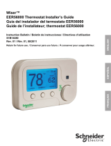
2. Pull the bottom edge of the cover and open the
thermostat controller as illustrated in Figure 1.
Note: PIR Models have a wiring connection
between the cover and the Printed Circuit Board
(PCB). This connection allows for proper wiring of
the occupancy sensor. Carefully remove the wiring
connection from the PCB by pulling up on the
connector block. Do not attempt to remove the
connector block by pulling on the wires.
This Class (A) digital apparatus meets all the
requirements of the Canadian Interference-Causing
Equipment Regulations.
Cet appareil numérique de la Classe (A) respecte
toutes les exigences du Règlement sur le matériel
brouilleur du Canada.
RF Transmitters: Industry Canada Statement
The term IC before the certification/registration
number only signifies that the Industry Canada
technical specifications were met.
Le terme « IC » précédant le numéro d'accréditation/
inscription signifie simplement que le produit est
conforme aux spécifications techniques d'Industrie
Canada.
Table 1: Recommended Transmission Ranges
Type Distance
Through Walls 10 m (32.8 ft)
Open Space 30 m (98.4 ft)
Figure 1: Removing the Thermostat Controller
Cover (TEC2004-4+PIR Model Shown)
FIG:cvr_rmvl

TEC2004-4 and TEC2004-4+PIR Multi-Stage Economizer Wireless Thermostat Controller
Installation Instructions
3
3. Carefully pull the locking tabs on the right side of
the mounting base and unlock the PCB. Open the
PCB to the left as illustrated in Figure 2.
4. Pull approximately 152 mm (6 in.) of wire from the
wall and insert the wire through the hole in the
mounting base.
5. Align the mounting base on the wall and use the
base as a template to mark the two mounting hole
locations.
6. Position the mounting base so that the arrow on
the base points upward to indicate the top of the
thermostat controller.
Note: If you need to install the thermostat on an
electrical junction box, use 2-1/2 x 4 in.
(63 x 101 mm) square boxes with mud ring covers,
and avoid smaller 1-1/2 x 4 in. (38 x 101 mm)
square or 3 x 2 in. (76 x 51 mm) boxes. This
procedure ensures you have enough space for
cabling and end-of-line devices, if needed.
Note: For surface-mount applications, use
durable mounting hardware, such as Molly bolt
anchors, that cannot be easily pulled out of the
mounting surface.
7. Secure the mounting base to the wall surface using
two mounting screws as illustrated in Figure 3.
Note: Be careful not to overtighten the mounting
screws.
8. Swing the PCB back to the right and carefully snap
it into the locking tabs on the mounting base.
9. Remove the screw terminal blocks that are
attached to a disposable adhesive. Figure 4
illustrates the locations of the screw terminal
blocks on the thermostat controller.
Figure 2: Opening the PCB
PCB
Locking
Tabs
F
I
G
:
p
r
n
t
d
_
c
r
c
t
_
b
r
d
Figure 3: Securing the Mounting Base to the Wall
F
I
G
:
m
n
t
n
g
_
b
s
Figure 4: Removing the Screw Terminal Blocks
F
I
G
:
t
r
m
n
l
_
b
l
c
k
s

TEC2004-4 and TEC2004-4+PIR Multi-Stage Economizer Wireless Thermostat Controller
Installation Instructions
4
Wiring
When replacing an existing thermostat controller,
remove and label the wires to identify the terminal
functions. When replacing a thermostat controller of the
same model, simply remove the old screw terminal
blocks and reinsert them onto the PCB of the
replacement thermostat controller.
To wire the thermostat controller:
1. Strip the ends of each wire 6 mm (1/4 in.) and
connect them to the appropriate screw terminals as
indicated in Figure 5.
Note: If multiple wires are inserted into the screw
terminals, be sure to properly twist the wires
together prior to inserting them into the screw
terminals.
2. Carefully push any excess wire back into the wall.
Note: Seal the hole in the wall with fireproof
material to prevent drafts from affecting the
ambient temperature readings.
3. Reinsert the screw terminal blocks onto the PCB.
4. Reattach the cover to the mounting base (top side
first).
5. Use a Phillips-head screwdriver to reinstall the
security screw on the bottom of the cover.
See Figure 5 for information on wiring the thermostat
controllers.
!
CAUTION: Risk of Electric Shock.
Disconnect power supply before making
electrical connections to avoid electric
shock.
!
CAUTION: Risk of Property Damage.
Do not apply power to the system before
checking all wiring connections. Short
circuited or improperly connected wires
may result in permanent damage to the
equipment.
IMPORTANT: Make all wiring connections in
accordance with local, national, and regional
regulations. Do not exceed the electrical ratings of
the thermostat controller.
24 VAC
Thermostat Power
Y2 Y1
RC C
If using the same power source
for the thermostat and heating loads,
install a jumper across RC and RH.
Heat 1
Heat 2
RH W1 W2
Aux
Aux
Cool 1
Energizes on a Call for First-Stage Cooling
Energizes on a Call for Second-Stage Cooling
Energizes Fan in Accordance with the Selected Fan Mode
24 VAC from Equipment Transformer
24 VAC (Common) from Equipment Transformer
24 VAC for Heating Stages
Energizes on a Call for First-Stage Heating
Energizes on a Call for Second-Stage Heating
Auxiliary Output
Configurable Digital Input 1
Configurable Digital Input 2
Remote Room Sensor
Sensor Common
Auxiliary/Outdoor Air Sensor
Remote Monitoring Supply Temperature Sensor
0 to 10 VDC Economizer Actuator Output
Function
Y1
Y2
G
RC
C
RH
W1
W2
Aux
DI1
DI2
RS
Scom
OS
MS
EC
Terminal
DI2
Scom
RS
DI1
Aux Contact (High Side Common)
• Lighting
• On/Off Actuation
• Exhaust Fan
OS
Auxiliary/
Outdoor
Air Sensor
EC
0 to 10
VDC
24 VAC
Common
Remote
Monitoring
Supply
Temperature
Sensor
Cool 2
FIG:wrng_2004-4
Y2
Y1
G
RC
C
RH W1 W2
DI1 DI2
RS
Scom
Five-Pole
Left Top Connector
Three-Pole
Right Top
Connector
Eight-Pole Bottom Connector
OS
MS
Aux
EC
G
Fan
Remote
Room
Sensor
Figure 5: Wiring the TEC2004-4 or TEC2004-4+PIR Thermostat Controller

TEC2004-4 and TEC2004-4+PIR Multi-Stage Economizer Wireless Thermostat Controller
Installation Instructions
5
Setup and Adjustments
Thermostat Controller User Interface Keys
The user interface consists of keys on the front cover
(Figure 6). The function of each key is as follows:
•Use the YES key to:
- confirm menu selections and to advance to the
next menu item
- stop the Status Display Menu from scrolling
and to manually scroll to the next parameter on
the menu
Note: When the thermostat controller is left
unattended for 45 seconds, the display resumes
scrolling.
•Use the NO key to decline a parameter change and
advance to the next menu item.
•Use the MENU key to:
- access the Main User Menu or to exit the menu
(See the Main User Menu
section.)
- access the Installer Configuration Menu or to
exit the menu (See the Configuring the
Thermostat Controller section.)
•Use the UP/DOWN arrow keys change the
configuration parameters and activate a setpoint
adjustment.
Light-Emitting Diodes (LEDs)
Three LEDs are included to indicate the fan status, call
for heat, or call for cooling:
• The fan LED is on when the fan is on.
• The heat LED is on when heating is on.
• The cool LED is on when cooling is on.
The Status LED, located beneath the cover, flashes at
5-second intervals to provide indication of the network
status of the thermostat controller. See Table 2.
Backlit Liquid Crystal Display (LCD)
The thermostat controller includes a 2-line, 8-character
backlit display. Low-level backlighting is present during
normal operation and brightens when any user
interface key is pressed. The backlight returns to low
level when the thermostat controller is left unattended
for 45 seconds.
Figure 6: Front Cover of Thermostat Controller (TEC2004-4+PIR Model Shown)
FIG:TEC2004-4_frnt
70.0ºF
Room Temp
Backlit, plain text
Liquid Crystal Display (LCD)
is easy to read in any condition.
Five keys on the thermostat controller
make operation easy and intuitive.
Light-Emitting Diodes (LEDs)
indicate system activity.
Status LED beneath cover
indicates network status.
PIR motion detector
saves energy using
standby setpoints.
Table 2: Status LED
Flashes per
5-Second
Interval
Condition Indicated
1 Power On
2 Power On, Communicating
3 Power On, Communicating, Found
Wireless Network
4 Power On, Communicating, Found
Wireless Network, Communicating with
TEC20 Coordinator

TEC2004-4 and TEC2004-4+PIR Multi-Stage Economizer Wireless Thermostat Controller
Installation Instructions
6
Integrated PIR Sensor –
TEC2004-4+PIR Thermostat Controller
The integrated PIR sensor allows for automatic
switching between fully adjustable Occupied and
Unoccupied temperature setpoints without user
interaction. This feature generates incremental energy
savings during scheduled occupied periods while the
space is unoccupied.
Programming Overview
Three menus are used to view, program, and configure
the TEC2004-4 and TEC2004-4+PIR Thermostat
Controllers: the Status Display Menu, the Main User
Menu, and the Installer Configuration Menu.
Status Display Menu
The Status Display Menu displays during normal
operation. This menu scrolls through several
parameters:
• Room Temperature
• System Mode
• Schedule Status (Occupied/Unoccupied/Override)
• Outdoor Temperature – An outdoor air temperature
sensor must be connected.
• Applicable Alarms – The backlight lights up as an
alarm condition is displayed.
Note: Press the YES key to temporarily stop this
menu from scrolling.
Note: An option is available within the Installer
Configuration Menu to lock out the scrolling display and
show only the Room Temperature parameter.
Main User Menu
Use the Main User Menu to access and change the
basic operating parameters of the thermostat controller.
Access the menu by pressing the MENU key during
normal thermostat controller operation.
Installer Configuration Menu
Use the Installer Configuration Menu to set up the
thermostat controller for application-specific operation.
To access the menu, press and hold the MENU key for
approximately 8 seconds.
Occupancy Sensor Operation –
TEC2004-4+PIR Thermostat Controller
A TEC2004-4+PIR Thermostat Controller (or a
TEC2004-4 Thermostat Controller equipped with a PIR
accessory cover) provides advanced occupancy logic.
Note: The PIR strategy is an occupied strategy. If the
thermostat controller is programmed to be Unoccupied,
the PIR function does not have an effect on the
occupancy strategy.
The thermostat controller automatically switches the
occupancy level between Occupied and Unoccupied as
required, when local movement is sensed. In the
Occupied mode, if no movement is detected beyond
the Unocc TM parameter setting, the mode changes to
Unoccupied. Once movement is detected, the mode
changes back to Occupied.
Occupancy sensing is enabled only if a PIR cover is
installed. The PIR cover is auto detected when
installed.
PIR Diagnostic LEDs
The diagnostic LEDs inside the PIR lens brighten when
movement is detected within the first 30 minutes after
powerup. The LEDs do not light up or brighten after the
initial 30-minute period.
Setpoints
The installer must be certain that the difference
between the Occupied and Unoccupied setpoints can
be recovered within a timely fashion to ensure
occupancy comfort. In addition, the difference between
the two setpoints must be large enough to warrant
maximum energy savings.
These setpoints and Unoccupied time are adjustable to
allow for customization, as dictated by the individual
space requirements. See Figure 7 for an example of
increasing room temperature setpoints.

TEC2004-4 and TEC2004-4+PIR Multi-Stage Economizer Wireless Thermostat Controller
Installation Instructions
7
Configuring the Thermostat Controller
The thermostat controller ships from the factory with
default settings for all configurable parameters. The
default settings are shown in Table 3. To reconfigure
the parameters via the thermostat controller, follow the
steps in this section.
1. To access the Installer Configuration Menu, press
and hold the MENU key for approximately
8 seconds.
Note: If the Password parameter is configured,
Password 0 appears on the thermostat controller
display indicating that the configured password is
required to proceed. Use the UP/DOWN arrow
keys to indicate the configured password, then
press the MENU key to proceed through the
Installer Configuration Menu parameters.
2. Once the Installer Configuration Menu begins,
release and press the NO key to scroll through the
parameters listed in Table 3.
3. When the desired parameter is displayed, use the
YES key to choose the desired selection option.
4. Press the YES key and then the NO key to
continue scrolling through the parameters.
When the thermostat controller is in the Installer
Configuration Menu and left unattended for
approximately 8 seconds, the thermostat controller
reverts to the Status Display Menu.
Configuring the Wireless Mesh Network
Settings
Use the following process to configure the wireless
mesh network settings.
1. Select a PAN ID and Channel. Use these same
values for every TEC Wireless Thermostat
Controller (and the associated coordinator) on the
same wireless mesh network.
2. Select a Com Address for each TEC Wireless
Thermostat Controller (1 to 254). This address
must be unique to each thermostat controller on
the same wireless network (that is, unique to the
PAN ID and Channel combination).
After configuring the wireless mesh network settings,
refer to the TEC20xx-4 and TEC20xx-4+PIR Series
Wireless Thermostat Controller System Technical
Bulletin (LIT-12011596) for directions on integrating the
TEC20xx-4 and TEC20xx-4+PIR Series Wireless
Thermostat Controllers and TEC20 Coordinator with a
supervisory controller.
Configuring Inputs DI1 and DI2
When DI1 and DI2 are configured for an alarm
condition, an alarm condition is displayed locally when
the input is closed. An alarm message is included on
the scrolling Status Display Menu and when the
message is displayed, the backlight momentarily
lights up.
Both inputs can be configured to the Selection Options
included in Table 3.
Figure 7: Increasing Room Temperature Setpoints
Occ Heat
= 72°F
Occ Cool
= 75°F
Unocc Heat
= 65°F
Room Temperature
FIG:rm_tmp

TEC2004-4 and TEC2004-4+PIR Multi-Stage Economizer Wireless Thermostat Controller
Installation Instructions
8
Table 3: Installer Configuration Menu (Part 1 of 5)
Parameter
Appearing
on Display
Description and Default Selection Options
Pswrd Sets the protective access
password to prevent unauthorized
access to the Installer Configuration
Menu.
Default: 0
Note: The default setting does not
lock out access to the Installer
Configuration Menu.
Range: 0 to 1,000
Com addr Wireless address at the thermostat
controller; Default: 254
Range: 000 to 254
Addresses of each item on the wireless bus must be uniquely
numbered, increasing from 1.
Note: Setting this parameter to 0 disables the function.
PAN ID Sets the Personal Area Network
Identification (PAN ID) of the
wireless network. All devices on a
network must have the same
PAN ID setting to communicate with
each other. Default: 0
Range: 0 to 500
Note: Setting this parameter to 0 disables the function.
Channel Sets the mesh network channel the
device uses for communication.
Only devices using the same mesh
network channel can communicate
with each other. Default: 10
Range: 11 to 26
Note: Setting this parameter to 10 disables the function.
GET FROM Parameter not available at this time. N/A
DI1 Configuration of Digital Input 1.
Default: None
(None): No function is associated with an input.
(RemNSB): Remote Night Setback (NSB) via a time clock input, an
occupancy sensor, or from a voltage-free contact.
Contact open = Occupied; contact closed = Unoccupied.
(RemOVR): Temporary occupancy request via a remote input. This
override function is controlled by a manual remote occupancy
override. When enabled, this condition disables the override
capability of the thermostat controller.
(Filter): A Filter alarm is displayed. This alarm can be connected to
a differential pressure switch that monitors a filter.
(Service): A Service alarm is displayed on the thermostat controller
when the input is energized. Tie this input into the air conditioning
unit control card, which provides an alarm if a malfunction occurs.
(Fan lock): A backlit flashing Fan lock alarm is displayed on the
thermostat controller when the input is not energized. This alarm is
used in conjunction with a local airflow sensor connected to the
input. The thermostat controller heating or cooling action is locked
out if no airflow is detected 10 seconds after the fan (Terminal G) is
energized. Contact open = no airflow; contact closed = airflow
present.

TEC2004-4 and TEC2004-4+PIR Multi-Stage Economizer Wireless Thermostat Controller
Installation Instructions
9
DI2 Configuration of Digital Input 2.
Default: None
(None): No function is associated with an input.
(RemNSB): Remote Night Setback (NSB) via a time clock input, an
occupancy sensor, or from a voltage-free contact.
Contact open = Occupied; contact closed = Unoccupied.
(RemOVR): Temporary occupancy request via a remote input. This
override function is controlled by a manual remote occupancy
override. When enabled, this condition disables the override
capability of the thermostat controller.
(Filter): A Filter alarm is displayed. This alarm can be connected to
a differential pressure switch that monitors a filter.
(Service): A Service alarm is displayed on the thermostat controller
when the input is energized. Tie this input into the air conditioning
unit control card, which provides an alarm if a malfunction occurs.
(Fan lock): A backlit flashing Fan lock alarm is displayed on the
thermostat controller when the input is not energized. This alarm is
used in conjunction with a local airflow sensor connected to the
input. The thermostat controller heating or cooling action is locked
out if no airflow is detected 10 seconds after the fan (Terminal G) is
energized. Contact open = no airflow; contact closed = airflow
present.
MenuScro Gives the option of having the
display continuously scroll the
parameters.
Default: on
(off): The scroll is inactive.
(on): The scroll is active.
Lockout Selectable Lockout Levels for
limiting end user keypad interaction.
Default: 0
Function Level
(0) (1) (2)
Resume/Override
Scheduling
Access Access No Access
Permanent
Temperature
Setpoints
Access No Access No Access
Temporary
Temperature
Setpoints
Access Access No Access
System Mode Setting Access No Access No Access
Fan Mode Setting Access No Access No Access
Pwr del
1
Sets the delay time period at
thermostat controller powerup, or at
each time power is removed and
reapplied, before any operation
(fan, heating, or cooling) is
authorized. Also can be used to
sequence the startup of multiple
units in one location.
Default: 10.0 sec
Range: 10.0 to 120.0 sec
Frost pr Provides a minimum heating
setpoint of 5.5°C/42.0°F to prevent
freezing in the zone controlled by
the thermostat controller.
Default: off
(on): Enabled
(off): Disabled
Heat max
2
Sets the Occupied and Unoccupied
maximum Heating setpoint values.
Default: 32.0°C/90.0°F
Range: 4.5°C/40.0°F to 32.0°C/90.0°F
Table 3: Installer Configuration Menu (Part 2 of 5)
Parameter
Appearing
on Display
Description and Default Selection Options

TEC2004-4 and TEC2004-4+PIR Multi-Stage Economizer Wireless Thermostat Controller
Installation Instructions
10
Cool min
2
Sets the Occupied and Unoccupied
minimum Cooling setpoint values.
Default: 12.0°C/54.0°F
Range: 12.0°C/54.0°F to 37.5°C/100.0°F
Pband Proportional Band used by the PI
temperature control loop of the
thermostat controller.
Pband is not converted with C or F
scale and is always shown with a
range of 2 to 8.
Default: 2 (2.0F°/1.1C°)
Value F Scale Pband/C Scale Pband
2 2.0F°/1.1C°
3 3.0F°/1.7C°
4 4.0F°/2.2C°
5 5.0F°/2.8C°
6 6.0F°/3.3C°
7 7.0F°/3.9C°
8 8.0F°/4.4C°
Note: The use of a larger proportional band is not to use the
thermostat controller as a discharge air controller device. The use of
a larger proportional band can be used to solve issues for flawed
HVAC design with basic sizing and thermostat controller location
errors that cannot be worked around.
Anticycl Anti-Short Cycle timer sets the
minimum on/off times for heating
and cooling stages.
Default: 2.0 min
Range: 0.0 to 5.0 min adjustable in 1-minute increments
Set the anti-short cycle timer to 0.0 min for equipment that already
has its own anti-short cycle timer.
Heat cph Sets the maximum number of
Heating cycles per hour.
Default: 4.0
Range: 3.0 to 8.0 cycles per hour
Cool cph Sets the maximum number of
Cooling cycles per hour.
Default: 4.0
Range: 3.0 or 4.0 cycles per hour
Deadband Sets the minimum deadband
between the heating and cooling
setpoints.
Default: 1.0C°/2.0F°
Range: 1.0C°/2.0F° to 2.0C°/4.0F° adjustable in 0.5C°/1.0F°
increments
Fan cont Determines how the fan is activated
in response to a call for heating or
cooling.
Default: on
(off): Enables the thermostat controller to activate the fan in
response to a call for cooling only.
(on): Enables the thermostat controller to activate the fan in
response to a call for heating or cooling.
When there is a call for auxiliary heating, the fan is activated by the
equipment fan and limit control.
Fan del Fan delay extends fan operation
after a heating or cooling cycle has
ended.
Default: off
(on): Extends fan operation by 60 seconds after a heating or cooling
cycle has ended.
(off): No extension of fan operation after a heating or cooling cycle
has ended.
The fan delay is only active when the fan is in the Auto mode.
Table 3: Installer Configuration Menu (Part 3 of 5)
Parameter
Appearing
on Display
Description and Default Selection Options

TEC2004-4 and TEC2004-4+PIR Multi-Stage Economizer Wireless Thermostat Controller
Installation Instructions
11
TOccTime Sets the duration of the Temporary
Occupancy Time (when the
thermostat controller is in the
Unoccupied mode) when a
Schedule Override Function is
enabled using either the Main User
Menu or DI1 or DI2 configured as a
temporary override remote contact
(RemOVR).
Sets the effective duration of the
Temporary heating or cooling
setpoints set using the
UP/DOWN arrow keys.
Default: 3.0 hrs
Range: 0.0 to 12.0 hrs adjustable in 1-hour increments
Cal RS Sets the desired room air
temperature sensor calibration
(offset). The offset can be added to
or subtracted from the actual
displayed room temperature.
Default: 0.0C°/0.0C°F
Range: -2.5C°/-5.0F° to 2.5C°/5.0F° adjustable in 0.5C°/1.0F°
increments
Cal OS Sets the desired outdoor air
temperature sensor calibration
(offset). The offset can be added to
or subtracted from the actual
displayed room temperature.
Default: 0.0C°/0.0F°
Range: -2.5C°/-5.0F° to 2.5C°/5.0F° adjustable in 0.5C°/1.0F°
increments
H stage Reverts the operation of a two-stage
thermostat controller to a
single-stage thermostat controller
when the second heating stage is
not needed.
Default: 2.0
(1.0): One Stage
(2.0): Two Stages
C stage Reverts the operation of a two-stage
thermostat controller to a
single-stage thermostat controller
when the second cooling stage is
not needed.
Default: 2.0
(1.0): One Stage
(2.0): Two Stages
H lock Disables heating stage(s) operation
when the outside air temperature is
greater than the configured value. If
the fan mode is set to Auto or
Smart, the fan output is also
disabled. Requires that an outside
air temperature sensor be installed
and connected.
Default: 120°F/49°C
Range: -15°F/-26°C to 120°F/49°C adjustable in 5F°/5C°
increments
C lock Disables cooling stage(s) operation
when the outside air temperature is
less than the configured value. If the
fan mode is set to Auto or Smart,
the fan output is also disabled.
Requires that an outside air
temperature sensor be installed and
connected.
Default: -40°F/-40°C
Range: -40°F/-40°C to 95°F/35°C adjustable in 5F°/5C° increments
Table 3: Installer Configuration Menu (Part 4 of 5)
Parameter
Appearing
on Display
Description and Default Selection Options

TEC2004-4 and TEC2004-4+PIR Multi-Stage Economizer Wireless Thermostat Controller
Installation Instructions
12
Aux cont Energizes peripheral devices
(lighting equipment, exhaust fans,
and economizers).
Default: n.o.
Note: The contact toggles with the
internal Occupied/Unoccupied
schedule (or the NSB contact on
one of the digital inputs, if used).
(n.c.): Contact open = Occupied; contact closed = Unoccupied
(n.o.): Contact closed = Occupied; contact open = Unoccupied
Chngstpt
2
Sets the economizer changeover
strategy, based on the outdoor air
temperature. Requires that an
outdoor air temperature sensor be
installed and connected.
When the OA temperature is below
the changeover setpoint, free
cooling is used (economizer
operation). When the OA
temperature is above the setpoint,
mechanical cooling is used
(compressor operation).
Default: 13.0°C/55.0°F
Range: -10.0°C/14.0°F to 21.0°C/70.0°F
Min pos Sets the minimum position for the
OA dampers on the economizer.
These dampers are energized to
minimum position when the fan
(Terminal G) is energized and the
thermostat controller is in the
Occupied mode. When the
schedule is in the Unoccupied
mode, the minimum position is 0%.
Default: 0.0%
Range: 0.0 to 100.0% equals 0 to 10 VDC output range
% OA Setting for 0 to 10 VDC
Actuator
Setting for 2 to 10 VDC
Actuator
(0.0%) 0% 0 to 20%
(5.0%) 5% 24%
(10.0%) 10% 28%
(15.0%) 15% 32%
(20.0%) 20% 36%
(25.0%) 25% 40%
(30.0%) 30% 44%
C mech Determines whether to allow
mechanical cooling (compressor
operation) if free cooling
(economizer operation) cannot
maintain the cooling setpoint.
Default: off
(on): Typically applies when the MS is installed before the
mechanical cooling refrigeration coils in the mixing plenum. In this
scenario, mechanical cooling is allowed when free cooling cannot
maintain the cooling setpoint.
(off): Typically applies when the remote Mixed air Sensor (MS) is
installed after the mechanical cooling refrigeration coils. In this
scenario, mechanical cooling will never operate at the same time as
free cooling.
Mix stpt
2
Establishes the mixed air
temperature when operating in the
economizer mode.
Default: 55.0°F/13.0°C
Range: 50.0°F/10.0°C to 90.0°/32.0°C
MS temp Displays the mixed air temperature.
Requires that an MS be installed
and connected.
Default: N/A
The mixed air temperature can be used to help service and
troubleshoot the equipment and the economizer operation. The
mixed air temperature is only accessible via the Installer
Configuration Menu.
1. When adjusting the numeric value, press the UP or DOWN arrow key to change the value by single increments; press and
hold the UP or DOWN arrow key to change the numeric value in increments of ten.
2. When adjusting the temperature, press the UP or DOWN arrow key to change the value in 0.5F°/0.5C° increments; press
and hold the UP or DOWN arrow key to change the value in 5.0F°/5.0C° increments.
Table 3: Installer Configuration Menu (Part 5 of 5)
Parameter
Appearing
on Display
Description and Default Selection Options

TEC2004-4 and TEC2004-4+PIR Multi-Stage Economizer Wireless Thermostat Controller
Installation Instructions
13
Operation
Programming the Thermostat Controller
After configuring the thermostat controller by means of
the Installer Configuration Menu, program its operating
parameters by means of the Main User Menu. Access
this menu by pressing the MENU key during normal
operation. The Main User Menu contains the basic
operating features of the thermostat controller.
The Main User Menu also uses Auto Help, which is
displayed automatically in the menu when there is a
pause in programming activity. To exit Auto Help,
continue with the programming selection. When the
thermostat controller is in the Main User Menu and is
left unattended for 45 seconds, the menu reverts to the
Status Display Menu.
Enabling Override Schedule
Note: The Override Schedule prompt only appears
when the thermostat controller is in the Unoccupied
Mode.
This menu selection gives the user the option of
overriding the unoccupied setpoints with the occupied
setpoints for the amount of time specified under the
TOccTime parameter. See Table 3.
Note: If one of the digital inputs is configured to
operate as a remote override contact, this menu is
disabled.
To override the unoccupied state while in the Main User
Menu:
1. Press the NO key to all prompts until the Override
Schedule prompt appears. If the thermostat
controller is in the unoccupied state, this is the first
prompt.
2. Press the YES key to enable the temporary
override. The thermostat controller returns to the
Status Display Menu.
When scrolling through the Status Display Menu,
Override now appears for the schedule status
parameter.
Resuming the Programmed Schedule
This menu only appears when the thermostat controller
is in the override mode.
To resume the schedule while in the Main User Menu:
1. Press the NO key to all prompts until the Resume
Schedule prompt appears. If the thermostat
controller is in the override state, this is the first
prompt.
2. Press the YES key to resume the programmed
schedule.
The thermostat controller returns to the Status Display
Menu.
Entering Permanent Temperature Setpoints
The first prompt appearing in the Main User Menu of
the thermostat controller when in the occupied state is
to set the permanent temperature setpoint. Permanent
setpoints are stored in the programmed schedule.
To enter the permanent heating and cooling setpoints
for the Occupied and Unoccupied Modes, follow the
steps in Table 4. When changing the temperatures,
press the keys once to change the temperature in
0.5C°/0.5F° increments; press and hold down the keys
to change the temperature in 5.0F°/5.0C° increments.
Table 4: Entering Permanent Temperature
Setpoints (Part 1 of 2)
Thermostat
Controller
Display
Description
Press the MENU key while in the
Status Display Menu to enter the
Main User Menu.
Press the NO key to all prompts until
the temperature setpoint prompt
appears on the display (it may be the
first prompt). Press the YES key to
enter the temperature setting menu.
Press the YES key to change the
occupied cooling setpoint. Press the
NO key to advance to the occupied
heating setpoint menu.
Press the UP/DOWN arrow keys to
set the temperature. Press the YES
key to store the value and advance to
the next menu.
Press the YES key to change the
occupied heating setpoint. Press the
NO key to advance to the unoccupied
cooling setpoint menu.
Press the UP/DOWN arrow keys to
set the temperature. Press the YES
key to store the value and advance to
the next menu.
Press the YES key to change the
unoccupied cooling setpoint. Press
the NO key to advance to the
unoccupied heating setpoint.
RoomTemp
75.0
°
F
Temperat
set? Y/N
Cooling
set? Y/N
Cooling
75.0
°
F
Heating
set? Y/N
Heating
68.0
°
F
Unocc CL
set? Y/N

TEC2004-4 and TEC2004-4+PIR Multi-Stage Economizer Wireless Thermostat Controller
Installation Instructions
14
Entering Temporary Temperature Setpoints
To temporarily change the setpoint, press the
UP/DOWN arrow keys to change the temporary
setpoint for the current mode of operation.
Note: Whether the thermostat controller is heating or
cooling, the respective setpoint is temporarily adjusted.
To toggle between the temporary heating and cooling
setpoints, press the NO key while changing the
temporary setpoints.
Ending Temporary Temperature Setpoints
The temporary setpoints remain in effect for the
duration set in the TOccTime parameter or until
manually released.
To release the temporary setpoint sooner, while in the
Main User Menu:
1. Press the YES key to the first prompt that appears.
2. If the thermostat controller does not immediately
return to the Status Display Menu, press the MENU
key again and press the YES key to exit the Main
User Menu.
The setpoint reverts to the Permanent Temperature
Setpoint.
Selecting the System Mode
The thermostat controller has four system modes:
• Automatic Mode (auto): Automatic changeover
between heating and cooling. This is the default
setting.
• Cooling Mode (cool): Cooling operation only
• Heating Mode (heat): Heating operation only
• Off Mode (off): The thermostat controller is off;
however, when frost protection (Frost pr
parameter) is enabled, the thermostat controller
still calls for heat (if required).
To set the system mode while in the Main User Menu:
1. Press the NO key to all prompts until the system
mode prompt appears on the display. Press the
YES key to select the desired system mode.
2. Press the UP/DOWN arrow keys to locate the
desired system mode. Press the YES key to select
the desired system mode.
3. Press the YES key to return to the Status Display
Menu or press the NO key to return to the system
mode selection menu.
Selecting the Fan Mode
The thermostat controller has three fan mode settings:
• On Fan Mode (on): Energizes the fan all the time
for both occupied and unoccupied states, even if
the system mode is set to off.
• Automatic Fan Mode (auto): Energizes the fan
only on a call for heating or cooling, for both
occupied and unoccupied states.
• Smart Fan Mode (smart): Energizes the fan all
the time for occupied states, and only on a call for
heating or cooling in unoccupied states. This is the
default setting.
To select the fan mode while in the Main User Menu:
1. Press the NO key to all prompts until the fan mode
prompt appears on the display. Press the YES key
to set the fan mode.
2. Press the UP/DOWN arrow keys to locate the
desired fan mode. Press the YES key to select the
desired fan mode.
3. Press the YES key to return to the Status Display
Menu or press the NO key to return to the fan
mode selection menu.
Press the UP/DOWN arrow keys to
set the temperature. Press the
YES
key to store the value and advance to
the next menu.
Press the
YES key to change the
unoccupied heating setpoint. Press
the
NO key to advance to the
temperature display units.
Press the
UP/DOWN arrow keys to
set the temperature. Press the
YES
key to store the value and advance to
the next menu.
Press the
YES key to set the display
units to °F or °C. Press the
NO key to
advance to the temperature setpoint
type menu.
Press the
YES key to return to the
Status Display Menu or press the
NO
key to reenter the temperature
setting menu.
Table 4: Entering Permanent Temperature
Setpoints (Part 2 of 2)
Thermostat
Controller
Display
Description
Unocc CL
80.0
°
F
Unocc HT
set? Y/N
Unocc HT
62.0
°
F
°
F/
°
C
set? Y/N
Exit?
Y/N

TEC2004-4 and TEC2004-4+PIR Multi-Stage Economizer Wireless Thermostat Controller
Installation Instructions
15
Troubleshooting
See Table 5 for display messaging. Refer to the
TEC20xx-4 and TEC20xx-4+PIR Series Wireless
Thermostat Controller System Technical Bulletin
(LIT-12011596) for troubleshooting details.
Accessories
All the accessories in Table 6 include mounting
hardware; contact the nearest Johnson Controls®
representative to order any of these parts.
Note: Review the technical specifications of the
accessories prior to their use in an application.
Repair Information
If a TEC2004-4 or TEC2004-4+PIR Wireless
Thermostat Controller fails to operate within its
specifications, replace the unit. For a replacement
thermostat controller, contact the nearest
Johnson Controls representative.
Table 5: Alarm Messages
Display Function
Frost Indicates that the heating is energized by the low limit frost protection room temperature setpoint 5.6°C (42°F).
Fan Lock Indicates that the heating and cooling action are locked out due to a defective fan operation.
Service Indicates that there is a service alarm in accordance with a programmable Digital Input.
Filter Indicates that the filter(s) is dirty in accordance with a programmable Digital Input.
Table 6: Accessories (Order Separately)
Code Number Description
SEN-600-1 Remote Indoor Air Temperature Sensor
SEN-600-4 Remote Indoor Air Temperature Sensor with Occupancy Override and LED
TEC-3-PIR
1
Cover with Occupancy Sensor
TE-6361M-1
2
Duct Mount Air Temperature Sensor
TE-6363P-1
2
Outside Air Temperature Sensor
TE-636S-1 Strap-Mount Temperature Sensor
TEC20-A-1 Replacement Antenna for TEC20 Coordinator
TEC20-RA-1
3
Remote Antenna for TEC20 Coordinator
NPB-PWR
4
DIN Rail Mount 24 VAC/DC Power Module for TEC20 Coordinator
TEC20-8X-1 120 VAC to 15 VDC Power Supply for TEC20 Coordinator
TEC20-9B-1 Replacement Battery Pack for TEC20 Coordinator
TEC20-3C-2 BACnet IP Wireless Coordinator; Requires 15 VDC Power Supply
TEC20-6C-2 BACnet MS/TP Wireless Coordinator; Requires 15 VDC Power Supply
1. The TEC-3-PIR Accessory Cover can be used to replace the existing cover on a non-PIR TEC2004-4 Thermostat
Controller to provide occupancy sensing capability.
2. Additional TE-636xx-x Series 10k ohm Johnson Controls Type II Thermistor Sensors are available; refer to the
TE-6300 Series Temperature Sensors Product Bulletin (LIT-216320) for more details.
3. This antenna is used when the TEC Coordinator is installed inside a metal cabinet, or when a remote antenna is required by
physical installation.
4. DIN Rail: Type NS35/7.5 (35 x 7.5 mm) and DIN rail end clips. Length of DIN rail depends on the number of DIN rail
mounted options.

Published in U.S.A. www.johnsoncontrols.com
TEC2004-4 and TEC2004-4+PIR Multi-Stage Economizer Wireless Thermostat Controller
Installation Instructions
16
Metasys® and Johnson Controls® are registered trademarks of Johnson Controls, Inc.
All other marks herein are the marks of their respective owners. © 2010 Johnson Controls, Inc.
Building Efficiency
507 E. Michigan Street, Milwaukee, WI 53202
Technical Specifications
TEC2004-4 and TEC2004-4+PIR Multi-Stage Economizer Wireless Thermostat Controllers
Power Requirements 19 to 30 VAC, 50/60 Hz, 2 VA (Terminals RC and C) at 24 VAC Nominal, Class 2 or
Safety Extra-Low Voltage (SELV)
Economizer Output Rating 0 to 10 VDC into 2k ohm Resistance (Minimum)
Relay/Triac Contact Rating 19 to 30 VAC, 1.0 A Maximum, 15 mA Minimum, 3.0 A In-Rush, Class 2 or SELV
Digital Inputs Voltage-Free Contacts across Terminal C to Terminals DI1 and DI2
Analog Inputs Resistive Inputs (RS and UI3) for 10k ohm Johnson Controls Type II Negative
Temperature Coefficient (NTC) Thermistor Sensors
Wire Size 18 AWG Maximum, 22 AWG Recommended
Transmission Range Through Walls: 10 m (32.8 ft)
Line-of-Sight (Open Space): 30 m (98.4 ft)
RF Band Direct-Sequence Spread-Spectrum Transmission; 2.4 GHz unlicensed band
Transmission Power 10 mW Maximum
Temperature Range Backlit Display: -40.0°C/ -40.0°F to 50.0°C/122.0°F
Heating Control: 4.5°C/40.0°F to 32.0°C/90.0°F in 0.5° Increments
Cooling Control: 12.0°C/54.0°F to 100.0°F/38.0°C in 0.5° Increments
Temperature Sensor Type Local 10k ohm Negative Temperature Coefficient (NTC) Thermistor
Resolution ±0.1C°/±0.2F°
Control Accuracy ±0.5C°/±0.9F° at 21.0°C/70.0°F Typical Calibrated
Auxiliary/Outdoor Air
Temperature Indication Range
-40.0°C/-40.0°F to 50.0°C/122.0°F
Minimum Deadband 1C°/2F° between Heating and Cooling
Ambient Conditions Operating: 0 to 50°C (32 to 122°F); 95% RH Maximum, Noncondensing
Storage:-30 to 50°C (-22 to 122°F); 95% RH Maximum, Noncondensing
Compliance United States:
UL Listed, File E27734, CCN XAPX,
Under UL 873, Temperature Indicating and Regulating Equipment
FCC Compliant to Part 15.247 Regulations for Low Power Unlicensed Transmitters
Canada:
UL Listed, File E27734, CCN XAPX7,
Under CSA C22.2 No. 24, Temperature Indicating and Regulating Equipment
Industry Canada, ICES-003
Shipping Weight TEC2004-4 Models: 0.75 lb (0.34 kg)
TEC2004-4+PIR Models: 0.77 lb (0.35 kg)
The performance specifications are nominal and conform to acceptable industry standards. For application at conditions beyond these
specifications, consult the local Johnson Controls office. Johnson Controls, Inc. shall not be liable for damages resulting from misapplication or
misuse of its products.
/