15
INSTALLATION INSTRUCTIONS DUCTED CCC
Installing unit with 3105007.XXX or 3105935.XXX
Return Air Cover, continued from page 14, column A.
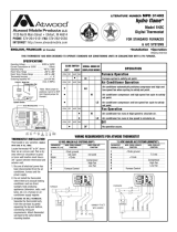
3. Place divider plate up to bottom of air conditioner
base pan firmly. The foam tape on the divider plate
must seal to bottom of base pan. See FIG. 17A.
Improper installation and sealing of divider
plate will cause the compressor to quick
cycle on the cold control. This may result in
fuse or circuit breaker opening and/or lack of
cooling.
FIG. 17A
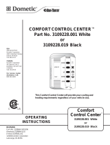
FIG. 18A
Note: The adhesive on the insulation is extremely
sticky. Be sure the part is located where desired
before pressing into place.
4. With slight pressure then push the divider plate
against the double sided tape on the ceiling tem-
plate.
5. Locate the 1/8” x 7” x 18” self -adhesive insulation
supplied with the return air kit. Remove the backing
paper from the insulation and carefully stick onto
the ceiling template divider panel. See FIG. 18A.
CAUTION
a. Excess width is intended to seal the divider plate
to the sides of the 14-1/4" x 14-1/4" (±1/8")
opening. This is to help prevent cold air discharge
from circulating into the air conditioner return
air opening.
b. If the insulation is too high, stick excess height
of insulation to the air conditioner base pan. Do
not cover up unit rating plate.
Installing unit with 3105007.XXX or 3105935.XXX
Return Air Cover, continued on page 16, column A.
Installing unit with 3308120.XXX Genesis Air Filtration
System, continued from page 14, column B.
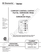
4. Use Aluminum foil tape (not supplied) to seal the
ends of the foam divider to the sides of the opening.
Make sure the area behind the flange on the ceiling
template is sealed. See FIG. 18B.
FIG. 18B
Use Aluminum Foil Tape To Seal the
Foam Divider To The Sides of 14-1/4"
x 14-1/4" (±1/8") Ceiling Opening
Make Sure To Seal
Behind Flange
Route wires
through Slot
Catch Flange In Groove Of
Return Air Cover
C. INSTALLATION OF INSIDE DECORATIVE COVER.
1. Install the slider in the return air cover and raise it
to the ceiling template. Route the wires from the
return air cover through the template slot leaving
about 3” between. Position wires where they can
be reached after plastic cover is installed. See FIG.
18B. Place the front of the return air cover against
the ceiling and slide towards the rear. The flange
on the ceiling template will catch in the groove on
the return cover. Adjust the position (right to left)
and install the front two screws. Start and tighten
the remaining screws to hold it in place.
Note: Number 10 cabinet screw can be used to
replace the two front screws to hold the plastic
cover flush to the ceiling. Connect together the wires
from the thermostat, control box and filter indica-
tor.
a. Connect the red wire from the air conditioner
the red wire from the filter indicator light with
the red positive 12VDC supply wire. See FIG.
18B.
b. Connect the black wire from the air conditioner,
the black wire from the filter indicator light with
the black negative 12VDC supply wire. See
FIG. 18B.
Note:
If solar panel is installed see instruc-
tions packaged with solar panel option.
Installing unit with 3308120.XXX Genesis Air Filtration
System, continued on page 16, column B.